1
SAFETY PRECAUTIONS
(Please read these instructions before using this equipment.)
Before using this product, please read this manual and the relevant manuals introduced in this manual
carefully and pay full attention to safety to handle the product correctly.
Refer to the Users manual of the CPU module to use for a description of the PLC system safety
precautions.
In this manual, the safety instructions are ranked as "DANGER" and "CAUTION".
DANGER
Indicates that incorrect handling may cause hazardous
conditions, resulting in death or severe injury.
CAUTION
Indicates that incorrect handling may cause hazardous
conditions, resulting in medium or slight personal injury or
physical damage.
CAUTION may also be linked to serious
Depending on circumstances, procedures indicated by
results.
In any case, it is important to follow the directions for usage.
Please save this manual to make it accessible when required and always forward it to the end user.
A-1
For Safe Operations
1. Prevention of electric shocks
DANGER
Never open the front case or terminal covers while the power is ON or the unit is running, as this
may lead to electric shocks.
Never run the unit with the front case or terminal cover removed. The high voltage terminal and
charged sections will be exposed and may lead to electric shocks.
Never open the front case or terminal cover at times other than wiring work or periodic
inspections even if the power is OFF. The insides of the module and servo amplifier are charged
and may lead to electric shocks.
Completely turn off the externally supplied power used in the system before mounting or removing
the module, performing wiring work, or inspections. Failing to do so may lead to electric shocks.
When performing wiring work or inspections, turn the power OFF, wait at least ten minutes, and
then check the voltage with a tester, etc. Failing to do so may lead to electric shocks.
Be sure to ground the module, servo amplifier and servomotor (Ground resistance: 100 or
less). Do not ground commonly with other devices.
The wiring work and inspections must be done by a qualified technician.
Wire the units after installing the module, servo amplifier and servomotor. Failing to do so may
lead to electric shocks or damage.
Never operate the switches with wet hands, as this may lead to electric shocks.
Do not damage, apply excessive stress, place heavy things on or sandwich the cables, as this
may lead to electric shocks.
Do not touch the module, servo amplifier, servomotor connector or terminal blocks while the
power is ON, as this may lead to electric shocks.
Do not touch the built-in power supply, built-in grounding or signal wires of the module and servo
amplifier, as this may lead to electric shocks.
2. For fire prevention
CAUTION
Install the module, servo amplifier, servomotor and regenerative resistor on incombustible.
Installing them directly or close to combustibles will lead to fire.
If a fault occurs in the module or servo amplifier, shut the power OFF at the servo amplifier's
power source. If a large current continues to flow, fire may occur.
When using a regenerative resistor, shut the power OFF with an error signal. The regenerative
resistor may abnormally overheat due to a fault in the regenerative transistor, etc., and may lead
to fire.
Always take heat measures such as flame proofing for the inside of the control panel where the
servo amplifier or regenerative resistor is installed and for the wires used. Failing to do so may
lead to fire.
Do not damage, apply excessive stress, place heavy things on or sandwich the cables, as this
may lead to fire.
A-2
3. For injury prevention
CAUTION
Do not apply a voltage other than that specified in the instruction manual on any terminal.
Doing so may lead to destruction or damage.
Do not mistake the terminal connections, as this may lead to destruction or damage.
Do not mistake the polarity ( + / - ), as this may lead to destruction or damage.
Do not touch the heat radiating fins of module or servo amplifier, regenerative resistor and
servomotor, etc., while the power is ON and for a short time after the power is turned OFF. In this
timing, these parts become very hot and may lead to burns.
Always turn the power OFF before touching the servomotor shaft or coupled machines, as these
parts may lead to injuries.
Do not go near the machine during test operations or during operations such as teaching.
Doing so may lead to injuries.
4. Various precautions
Strictly observe the following precautions. Mistaken handling of the unit may lead to faults,
injuries or electric shocks.
(1) System structure
CAUTION
Always install a leakage breaker on the module and servo amplifier power source.
If installation of an electromagnetic contactor for power shut off during an error, etc., is specified in
the instruction manual for the servo amplifier, etc., always install the electromagnetic contactor.
Install the emergency stop circuit externally so that the operation can be stopped immediately and
the power shut off.
Use the module, servo amplifier, servomotor and regenerative resistor with the correct
combinations listed in the instruction manual. Other combinations may lead to fire or faults.
Use the CPU module and Simple Motion module with the correct combinations listed in the
instruction manual. Other combinations may lead to faults.
If safety standards (ex., robot safety rules, etc.,) apply to the system using the module, servo
amplifier and servomotor, make sure that the safety standards are satisfied.
Construct a safety circuit externally of the module or servo amplifier if the abnormal operation of
the module or servo amplifier differ from the safety directive operation in the system.
In systems where coasting of the servomotor will be a problem during the forced stop, emergency
stop, servo OFF or power supply OFF, use dynamic brakes.
Make sure that the system considers the coasting amount even when using dynamic brakes.
In systems where perpendicular shaft dropping may be a problem during the forced stop,
emergency stop, servo OFF or power supply OFF, use both dynamic brakes and electromagnetic
brakes.
The dynamic brakes must be used only on errors that cause the forced stop, emergency stop, or
servo OFF. These brakes must not be used for normal braking.
The brakes (electromagnetic brakes) assembled into the servomotor are for holding applications,
and must not be used for normal braking.
A-3
CAUTION
The system must have a mechanical allowance so that the machine itself can stop even if the
stroke limits switch is passed through at the max. speed.
Use wires and cables that have a wire diameter, heat resistance and bending resistance
compatible with the system.
Use wires and cables within the length of the range described in the instruction manual.
The ratings and characteristics of the parts (other than module, servo amplifier and servomotor)
used in a system must be compatible with the module, servo amplifier and servomotor.
Install a cover on the shaft so that the rotary parts of the servomotor are not touched during
operation.
There may be some cases where holding by the electromagnetic brakes is not possible due to the
life or mechanical structure (when the ball screw and servomotor are connected with a timing belt,
etc.). Install a stopping device to ensure safety on the machine side.
(2) Parameter settings and programming
CAUTION
Set the parameter values to those that are compatible with the module, servo amplifier,
servomotor and regenerative resistor model and the system application. The protective functions
may not function if the settings are incorrect.
The regenerative resistor model and capacity parameters must be set to values that conform to
the operation mode and servo amplifier. The protective functions may not function if the settings
are incorrect.
Set the mechanical brake output and dynamic brake output validity parameters to values that are
compatible with the system application. The protective functions may not function if the settings
are incorrect.
Set the stroke limit input validity parameter to a value that is compatible with the system
application. The protective functions may not function if the setting is incorrect.
Set the servomotor encoder type (increment, absolute position type, etc.) parameter to a value
that is compatible with the system application. The protective functions may not function if the
setting is incorrect.
Set the servomotor capacity and type (standard, low-inertia, flat, etc.) parameter to values that
are compatible with the system application. The protective functions may not function if the
settings are incorrect.
Set the servo amplifier capacity and type parameters to values that are compatible with the
system application. The protective functions may not function if the settings are incorrect.
Use the program commands for the program with the conditions specified in the instruction
manual.
Set the sequence function program capacity setting, device capacity, latch validity range, I/O
assignment setting, and validity of continuous operation during error detection to values that are
compatible with the system application. The protective functions may not function if the settings
are incorrect.
A-4
CAUTION
Some devices used in the program have fixed applications, so use these with the conditions
specified in the instruction manual.
The input devices and data registers assigned to the link will hold the data previous to when
communication is terminated by an error, etc. Thus, an error correspondence interlock program
specified in the instruction manual must be used.
Use the interlock program specified in the intelligent function module's instruction manual for the
program corresponding to the intelligent function module.
(3) Transportation and installation
CAUTION
Transport the product with the correct method according to the mass.
Use the servomotor suspension bolts only for the transportation of the servomotor. Do not
transport the servomotor with machine installed on it.
Do not stack products past the limit.
When transporting the module or servo amplifier, never hold the connected wires or cables.
When transporting the servomotor, never hold the cables, shaft or detector.
When transporting the module or servo amplifier, never hold the front case as it may fall off.
When transporting, installing or removing the module or servo amplifier, never hold the edges.
Install the unit according to the instruction manual in a place where the mass can be withstood.
Do not get on or place heavy objects on the product.
Always observe the installation direction.
Keep the designated clearance between the module or servo amplifier and control panel inner
surface or the module and servo amplifier, module or servo amplifier and other devices.
Do not install or operate modules, servo amplifiers or servomotors that are damaged or that have
missing parts.
Do not block the intake/outtake ports of the servo amplifier and servomotor with cooling fan.
Do not allow conductive matter such as screw or cutting chips or combustible matter such as oil
enter the module, servo amplifier or servomotor.
The module, servo amplifier and servomotor are precision machines, so do not drop or apply
strong impacts on them.
Securely fix the module, servo amplifier and servomotor to the machine according to the
instruction manual. If the fixing is insufficient, these may come off during operation.
Always install the servomotor with reduction gears in the designated direction. Failing to do so
may lead to oil leaks.
A-5
CAUTION
Store and use the unit in the following environmental conditions.
Environment
Ambient
temperature
Ambient humidity
Storage
temperature
Atmosphere
Altitude
Vibration
Conditions
Module/Servo amplifier
According to each instruction manual.
According to each instruction manual.
According to each instruction manual.
Servomotor
0°C to +40°C (With no freezing)
(32°F to +104°F)
80% RH or less
(With no dew condensation)
-20°C to +65°C
(-4°F to +149°F)
Indoors (where not subject to direct sunlight).
No corrosive gases, flammable gases, oil mist or dust must exist
1000m (3280.84ft.) or less above sea level
According to each instruction manual
When coupling with the servomotor shaft end, do not apply impact such as by hitting with a
hammer. Doing so may lead to detector damage.
Do not apply a load larger than the tolerable load onto the servomotor shaft. Doing so may lead
to shaft breakage.
When not using the module for a long time, disconnect the power line from the module or servo
amplifier.
Place the module and servo amplifier in static electricity preventing vinyl bags and store.
When storing for a long time, please contact with our sales representative.
Also, execute a trial operation.
Make sure that the connectors for the servo amplifier and peripheral devices have been securely
installed until a click is heard.
Not doing so could lead to a poor connection, resulting in erroneous input and output.
(4) Wiring
CAUTION
Correctly and securely wire the wires. Reconfirm the connections for mistakes and the terminal
screws for tightness after wiring. Failing to do so may lead to run away of the servomotor.
After wiring, install the protective covers such as the terminal covers to the original positions.
Do not install a phase advancing capacitor, surge absorber or radio noise filter (option FR-BIF) on
the output side of the servo amplifier.
Correctly connect the output side (terminal U, V, W). Incorrect connections will lead the
servomotor to operate abnormally.
Do not connect a commercial power supply to the servomotor, as this may lead to trouble.
A-6
CAUTION
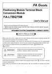
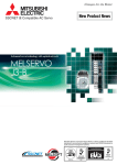
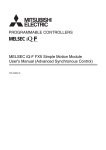
Do not mistake the direction of the surge absorbing diode installed on the DC relay for the control
signal output of brake signals, etc. Incorrect installation may lead to signals not being output
when trouble occurs or the protective functions not functioning.
Servo amplifier
DOCOM
Servo amplifier
24VDC
DOCOM
DICOM
DICOM
Control output
signal
24VDC
Control output
signal
RA
RA
Do not connect or disconnect the connection cables between each unit, the encoder cable or
PLC expansion cable while the power is ON.
Securely tighten the cable connector fixing screws and fixing mechanisms. Insufficient fixing may
lead to the cables combing off during operation.
Do not bundle the power line or cables.
Use applicable solderless terminals and tighten them with the specified torque.
If any solderless spade terminal is used, it may be disconnected when the terminal screw comes
loose, resulting in failure.
(5) Trial operation and adjustment
CAUTION
Confirm and adjust the program and each parameter before operation. Unpredictable
movements may occur depending on the machine.
Extreme adjustments and changes may lead to unstable operation, so never make them.
When using the absolute position system function, on starting up, and when the module or
absolute value motor has been replaced, always perform a home position return.
Before starting test operation, set the parameter speed limit value to the slowest value, and make
sure that operation can be stopped immediately by the forced stop, etc. if a hazardous state
occurs.
A-7
(6) Usage methods
CAUTION
Immediately turn OFF the power if smoke, abnormal sounds or odors are emitted from the
module, servo amplifier or servomotor.
Always execute a test operation before starting actual operations after the program or parameters
have been changed or after maintenance and inspection.
Do not attempt to disassemble and repair the units excluding a qualified technician whom our
company recognized.
Do not make any modifications to the unit.
Keep the effect or electromagnetic obstacles to a minimum by installing a noise filter or by using
wire shields, etc.
Electromagnetic obstacles may affect the electronic devices used near the module or servo
amplifier.
When using the CE Mark-compliant equipment design, refer to the "EMC Installation Guidelines"
(data number IB(NA)-67339) and refer to the corresponding EMC guideline information for the
servo amplifiers and other equipment.
Note that when the reference axis speed is designated for interpolation operation, the speed of
the partner axis (2nd axis, 3rd axis and 4th axis) may be larger than the set speed (larger than
the speed limit value).
Use the units with the following conditions.
1) LD77MH
Item
Conditions
L61P
L63P
+10%
Input power
+30%
100 to 240VAC -15%
(85 to 264VAC)
Input frequency
Tolerable momentary
power failure
24VDC -35%
(15.6 to 31.2VDC)
50/60Hz ±5%
10ms or less
2) QD77MS
Item
Input power
Input frequency
Tolerable momentary
power failure
Conditions
According to each instruction manual.
According to each instruction manual.
According to each instruction manual.
A-8
(7) Corrective actions for errors
CAUTION
If an error occurs in the self diagnosis of the module or servo amplifier, confirm the check details
according to the instruction manual, and restore the operation.
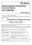
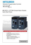
If a dangerous state is predicted in case of a power failure or product failure, use a servomotor
with electromagnetic brakes or install a brake mechanism externally.
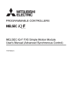
Use a double circuit construction so that the electromagnetic brake operation circuit can be
operated by emergency stop signals set externally.
Shut off with the
emergency stop
signal (EMG).
Shut off with servo ON signal OFF,
alarm, electromagnetic brake signal.
Servo motor
RA1
EMG
Electromagnetic
brakes
24VDC
If an error occurs, remove the cause, secure the safety and then resume operation after alarm
release.
The unit may suddenly resume operation after a power failure is restored, so do not go near the
machine. (Design the machine so that personal safety can be ensured even if the machine
restarts suddenly.)
(8) Maintenance, inspection and part replacement
CAUTION
Perform the daily and periodic inspections according to the instruction manual.
Perform maintenance and inspection after backing up the program and parameters for the
module and servo amplifier.
Do not place fingers or hands in the clearance when opening or closing any opening.
Periodically replace consumable parts such as batteries according to the instruction manual.
Do not touch the lead sections such as ICs or the connector contacts.
Before touching the module, always touch grounded metal, etc. to discharge static electricity from
human body. Failure to do so may cause the module to fail or malfunction.
Do not directly touch the module's conductive parts and electronic components.
Touching them could cause an operation failure or give damage to the module.
Do not place the module or servo amplifier on metal that may cause a power leakage or wood,
plastic or vinyl that may cause static electricity buildup.
Do not perform a megger test (insulation resistance measurement) during inspection.
When replacing the module or servo amplifier, always set the new module settings correctly.
A-9
CAUTION
When the module or absolute value motor has been replaced, carry out a home position return
operation using one of the following methods, otherwise position displacement could occur.
1) After writing the servo data to the Simple Motion module using programming software, switch
on the power again, then perform a home position return operation.
After maintenance and inspections are completed, confirm that the position detection of the
absolute position detector function is correct.
Do not drop or impact the battery installed to the module.
Doing so may damage the battery, causing battery liquid to leak in the battery. Do not use the
dropped or impacted battery, but dispose of it.
Do not short circuit, charge, overheat, incinerate or disassemble the batteries.
The electrolytic capacitor will generate gas during a fault, so do not place your face near the
module or servo amplifier.
The electrolytic capacitor and fan will deteriorate. Periodically replace these to prevent secondary
damage from faults. Replacements can be made by our sales representative.
Lock the control panel and prevent access to those who are not certified to handle or install
electric equipment.
Do not mount/remove the module or terminal block more than 50 times (IEC61131-2-compliant),
after the first use of the product. Failure to do so may cause malfunction.
Do not burn or break a module and servo amplifier. Doing so may cause a toxic gas.
(9) About processing of waste
When you discard module, servo amplifier, a battery (primary battery) and other option articles,
please follow the law of each country (area).
CAUTION
This product is not designed or manufactured to be used in equipment or systems in situations
that can affect or endanger human life.
When considering this product for operation in special applications such as machinery or systems
used in passenger transportation, medical, aerospace, atomic power, electric power, or
submarine repeating applications, please contact your nearest Mitsubishi sales representative.
Although this product was manufactured under conditions of strict quality control, you are strongly
advised to install safety devices to forestall serious accidents when it is used in facilities where a
breakdown in the product is likely to cause a serious accident.
(10) General cautions
CAUTION
All drawings provided in the instruction manual show the state with the covers and safety
partitions removed to explain detailed sections. When operating the product, always return the
covers and partitions to the designated positions, and operate according to the instruction
manual.
A - 10
CONDITIONS OF USE FOR THE PRODUCT
(1) Mitsubishi programmable controller ("the PRODUCT") shall be used in conditions;
i) where any problem, fault or failure occurring in the PRODUCT, if any, shall not lead to any major or
serious accident; and
ii) where the backup and fail-safe function are systematically or automatically provided outside of the
PRODUCT for the case of any problem, fault or failure occurring in the PRODUCT.
(2) The PRODUCT has been designed and manufactured for the purpose of being used in general industries.
MITSUBISHI SHALL HAVE NO RESPONSIBILITY OR LIABILITY (INCLUDING, BUT NOT LIMITED TO
ANY AND ALL RESPONSIBILITY OR LIABILITY BASED ON CONTRACT, WARRANTY, TORT,
PRODUCT LIABILITY) FOR ANY INJURY OR DEATH TO PERSONS OR LOSS OR DAMAGE TO
PROPERTY CAUSED BY the PRODUCT THAT ARE OPERATED OR USED IN APPLICATION NOT
INTENDED OR EXCLUDED BY INSTRUCTIONS, PRECAUTIONS, OR WARNING CONTAINED IN
MITSUBISHI'S USER, INSTRUCTION AND/OR SAFETY MANUALS, TECHNICAL BULLETINS AND
GUIDELINES FOR the PRODUCT.
("Prohibited Application")
Prohibited Applications include, but not limited to, the use of the PRODUCT in;
• Nuclear Power Plants and any other power plants operated by Power companies, and/or any other cases
in which the public could be affected if any problem or fault occurs in the PRODUCT.
• Railway companies or Public service purposes, and/or any other cases in which establishment of a
special quality assurance system is required by the Purchaser or End User.
• Aircraft or Aerospace, Medical applications, Train equipment, transport equipment such as Elevator and
Escalator, Incineration and Fuel devices, Vehicles, Manned transportation, Equipment for Recreation and
Amusement, and Safety devices, handling of Nuclear or Hazardous Materials or Chemicals, Mining and
Drilling, and/or other applications where there is a significant risk of injury to the public or property.
Notwithstanding the above, restrictions Mitsubishi may in its sole discretion, authorize use of the
PRODUCT in one or more of the Prohibited Applications, provided that the usage of the PRODUCT is
limited only for the specific applications agreed to by Mitsubishi and provided further that no special quality
assurance or fail-safe, redundant or other safety features which exceed the general specifications of the
PRODUCTs are required. For details, please contact the Mitsubishi representative in your region.
A - 11
INTRODUCTION
Thank you for purchasing the Mitsubishi MELSEC-Q/L series programmable controllers.
This manual describes the functions and programming of the Simple Motion module.
Before using this product, please read this manual and the relevant manuals carefully and develop familiarity
with the functions and performance of the MELSEC-Q/L series programmable controller to handle the
product correctly.
When applying the program examples introduced in this manual to the actual system, ensure the applicability
and confirm that it will not cause system control problems.
Please make sure that the end users read this manual.
REMARK
• Unless otherwise specified, this manual describes the program examples in which
the I/O numbers of X/Y00 to X/Y1F are assigned for a Simple Motion module. I/O
number assignment is required for using the program examples described in the
manual.
For I/O number assignment, refer to the following.
• MELSEC-Q CPU Module User's Manual (Function Explanation, Program
Fundamentals)
• MELSEC-L CPU Module User's Manual (Function Explanation, Program
Fundamentals)
• Operating procedures are explained using GX Works2.
A - 12
REVISIONS
The manual number is given on the bottom left of the back cover.
Print Date
Manual Number
Mar., 2011
Feb., 2012
IB(NA)-0300174-A
IB(NA)-0300174-B
Revision
First edition
[Additional model]
QD77MS
[Additional correction/partial correction]
Processing time of cam auto-generation
Japanese Manual Version IB-0300166
This manual confers no industrial property rights or any rights of any other kind, nor does it confer any patent licenses.
Mitsubishi Electric Corporation cannot be held responsible for any problems involving industrial property rights which
may occur as a result of using the contents noted in this manual.
© 2011 MITSUBISHI ELECTRIC CORPORATION
A - 13
CONTENTS
SAFETY PRECAUTIONS..............................................................................................................................A- 1
CONDITIONS OF USE FOR THE PRODUCT .............................................................................................A-11
INTRODUCTION............................................................................................................................................A-12
REVISIONS ....................................................................................................................................................A-13
CONTENTS....................................................................................................................................................A-14
COMPLIANCE WITH THE EMC AND LOW VOLTAGE DIRECTIVES.......................................................A-17
RELEVANT MANUALS .................................................................................................................................A-17
MANUAL PAGE ORGANIZATION................................................................................................................A-20
TERMS ...........................................................................................................................................................A-21
PACKING LIST...............................................................................................................................................A-22
1. Outline of Synchronous Control
1- 1 to 1-16
1.1 Outline of synchronous control ................................................................................................................ 1- 2
1.2 Performance specifications...................................................................................................................... 1- 6
1.3 Restrictions by the SERIAL No. and version .......................................................................................... 1- 8
1.4 General configuration of buffer memory (Synchronous control area) .................................................... 1- 9
1.5 Operation method of synchronous control .............................................................................................. 1-10
1.5.1 Synchronous control execution procedure....................................................................................... 1-10
1.5.2 Setting items for positioning parameters .......................................................................................... 1-11
1.5.3 Starting/ending for synchronous control........................................................................................... 1-13
1.5.4 Stop operation of output axis ............................................................................................................ 1-15
2. Input Axis Module
2- 1 to 2-30
2.1 Servo input axis........................................................................................................................................ 2- 2
2.1.1 Overview of servo input axis ............................................................................................................. 2- 2
2.1.2 Servo input axis parameters ............................................................................................................. 2- 4
2.1.3 Servo input axis monitor data ........................................................................................................... 2- 8
2.2 Synchronous encoder axis ...................................................................................................................... 2-10
2.2.1 Overview of synchronous encoder axis............................................................................................ 2-10
2.2.2 Setting method for synchronous encoder ........................................................................................ 2-13
2.2.3 Synchronous encoder axis parameters............................................................................................ 2-17
2.2.4 Synchronous encoder axis control data ........................................................................................... 2-24
2.2.5 Synchronous encoder axis monitor data.......................................................................................... 2-28
3. Cam Function
3- 1 to 3-18
3.1 Control details for cam function ............................................................................................................... 3- 2
3.2 Create cam data....................................................................................................................................... 3- 9
3.2.1 Memory configuration of cam data ................................................................................................... 3- 9
3.2.2 Cam data operation function............................................................................................................. 3-11
3.2.3 Cam auto-generation function .......................................................................................................... 3-15
4. Synchronous Control
4- 1 to 4-62
4.1 Main shaft module.................................................................................................................................... 4- 2
A - 14
4.1.1 Overview of main shaft module ........................................................................................................ 4- 2
4.1.2 Main shaft parameters ...................................................................................................................... 4- 3
4.1.3 Main shaft clutch parameters............................................................................................................ 4- 5
4.1.4 Main shaft clutch control data ........................................................................................................... 4-13
4.2 Auxiliary shaft module.............................................................................................................................. 4-14
4.2.1 Overview of auxiliary shaft module................................................................................................... 4-14
4.2.2 Auxiliary shaft parameters ................................................................................................................ 4-15
4.2.3 Auxiliary shaft clutch parameters...................................................................................................... 4-17
4.2.4 Auxiliary shaft clutch control data ..................................................................................................... 4-25
4.3 Clutch........................................................................................................................................................ 4-26
4.3.1 Overview of clutch ............................................................................................................................. 4-26
4.3.2 Control method for clutch.................................................................................................................. 4-26
4.3.3 Smoothing method for clutch ............................................................................................................ 4-33
4.3.4 Use example of clutch....................................................................................................................... 4-37
4.4 Speed change gear module .................................................................................................................... 4-38
4.4.1 Overview of speed change gear module.......................................................................................... 4-38
4.4.2 Speed change gear parameters ....................................................................................................... 4-39
4.5 Output axis module .................................................................................................................................. 4-41
4.5.1 Overview of output axis module........................................................................................................ 4-41
4.5.2 Output axis parameters..................................................................................................................... 4-43
4.6 Synchronous control change function ..................................................................................................... 4-47
4.6.1 Overview of synchronous control change function .......................................................................... 4-47
4.6.2 Synchronous control change control data........................................................................................ 4-48
4.7 Synchronous control monitor data........................................................................................................... 4-53
4.8 Phase compensation function ................................................................................................................. 4-58
4.9 Output axis sub functions ........................................................................................................................ 4-60
5. Synchronous Control Initial Position
5- 1 to 5-24
5.1 Synchronous control initial position ......................................................................................................... 5- 2
5.2 Synchronous control initial position parameters ..................................................................................... 5- 7
5.3 Cam axis position restoration method..................................................................................................... 5-11
5.3.1 Cam axis current value per cycle restoration ................................................................................... 5-11
5.3.2 Cam reference position restoration .................................................................................................. 5-15
5.3.3 Cam axis current feed value restoration........................................................................................... 5-16
5.4 Synchronous control analysis mode........................................................................................................ 5-17
5.5 Cam position calculation function ............................................................................................................ 5-19
5.5.1 Cam position calculation control data............................................................................................... 5-20
5.5.2 Cam position calculation monitor data ............................................................................................. 5-22
5.6 Method to restart synchronous control.................................................................................................... 5-23
6. Troubleshooting (Synchronous Control)
6- 1 to 6-14
6.1 Error and warning details ......................................................................................................................... 6- 2
6.2 Error and warning of input axis ................................................................................................................ 6- 3
6.2.1 List of input axis errors ...................................................................................................................... 6- 4
6.2.2 List of input axis warnings ................................................................................................................. 6- 5
6.3 Error and warning of output axis.............................................................................................................. 6- 6
6.3.1 List of output axis errors.................................................................................................................... 6- 6
6.3.2 List of output axis warnings............................................................................................................... 6-10
6.4 Warning of cam operation........................................................................................................................ 6-11
A - 15
6.4.1 List of cam data operation warnings................................................................................................. 6-11
6.4.2 List of cam auto-generation warnings .............................................................................................. 6-13
6.4.3 List of cam position calculation warnings ......................................................................................... 6-14
Appendices
Appendix- 1 to Appendix-18
Appendix 1 Comparisons with the Motion controller SV22 .............................................................Appendix- 2
Appendix 2 Sample program of synchronous control......................................................................Appendix- 6
Appendix 3 Lists of buffer memory address for synchronous control .............................................Appendix-10
A - 16
COMPLIANCE WITH THE EMC AND LOW VOLTAGE DIRECTIVES
(1) For programmable controller system
To configure a system meeting the requirements of the EMC and Low Voltage
Directives when incorporating the Mitsubishi programmable controller (EMC and
Low Voltage Directives compliant) into other machinery or equipment, refer to
"Safety Guidelines" that is supplied with the PLC CPU module. Also, refer to
"Example of measure against noise for compliance with the EMC directive" of the
following.
• The Section 4.3.1 of the "MELSEC-Q QD77MS Simple Motion Module User's
Manual (Positioning Control)"
• The Section 4.3.1 of the "MELSEC-L LD77MH Simple Motion Module User's
Manual (Positioning Control)"
The CE mark, indicating compliance with the EMC and Low Voltage Directives, is
printed on the rating plate of the programmable controller.
(2) For the product
To make this product comply with EMC and Low Voltage Directives, refer to
Section 4.3.1 "Precautions for wiring" of the following.
• "MELSEC-Q QD77MS Simple Motion Module User's Manual (Positioning
Control)"
• "MELSEC-L LD77MH Simple Motion Module User's Manual (Positioning
Control)"
RELEVANT MANUALS
(1) Simple motion module
Manual Name
Description
<Manual number (model code)>
MELSEC-Q QD77MS Simple Motion Module User's Manual
(Positioning Control)
Specifications of the QD77MS and information on how to
establish a system, maintenance and inspection, and
troubleshooting
<IB-0300185ENG, 1XB947>
MELSEC-L LD77MH Simple Motion Module User's Manual
(Positioning Control)
Functions, programming and buffer memory for the
positioning control of the QD77MS
Specifications of the LD77MH and information on how to
establish a system, maintenance and inspection, and
troubleshooting
<IB-0300172ENG, 1XB942>
Functions, programming and buffer memory for the
positioning control of the LD77MH
MELSEC-Q/L QD77MS/LD77MH Simple Motion Module
User's Manual
Functions, programming and buffer memory for the
(Synchronous Control)
synchronous control of the Simple Motion Module
<IB-0300174ENG, 1XB943>
A - 17
(2) CPU module
Manual Name
Description
<Manual number (model code)>
QCPU User's Manual
Specifications of the CPU modules, power supply modules,
(Hardware Design, Maintenance and Inspection)
display unit, SD memory cards, and batteries, information on
how to establish a system, maintenance and inspection, and
<SH-080483ENG, 13JR73> troubleshooting
QnUCPU User's Manual
Functions and devices of the CPU module, and
(Function Explanation, Program Fundamentals)
<SH-080807ENG, 13JZ27>
programming
MELSEC-L CPU Module User's Manual
Specifications of the CPU modules, power supply modules,
(Hardware Design, Maintenance and Inspection)
display unit, SD memory cards, and batteries, information on
how to establish a system, maintenance and inspection, and
<SH-080890ENG, 13JZ36> troubleshooting
MELSEC-L CPU Module User's Manual
Functions and devices of the CPU module, and
(Function Explanation, Program Fundamentals)
<SH-080889ENG, 13JZ35>
programming
(3) Programming tool
Manual Name
Description
<Manual number (model code)>
GX Works2 Version1 Operating Manual
System configuration, parameter settings, and online
(Common)
operations (common to Simple project and Structured
<SH-080779ENG, 13JU63> project) of GX Works2
GX Works2 Version1 Operating Manual
Parameter settings, monitoring, and operations of the
(Intelligent Function Module)
predefined protocol support function of intelligent function
<SH-080921ENG, 13JU69> modules, using GX Works2
GX Developer Version 8 Operating Manual
Operating methods of GX Developer, such as programming,
<SH-080373E, 13JU41> printing, monitoring, and debugging
GX Configurator-QP Version 2 Operating Manual
Data creation (such as parameters and positioning data)
and operations of transferring data to modules, positioning
monitor, and tests using GX Configurator-QP
<SH-080172, 13JU19>
1
(sold separately) *
1: The manual is included in the CD-ROM of the software package in a PDF-format file.
For users interested in buying the manual separately, a printed version is available. Please contact us with the manual
number (model code) in the list above.
A - 18
(4) Servo amplifier
Manual Name
Description
<Manual number (model code)>
SSCNET /H interface MR-J4- B Servo amplifier
This manual explains the I/O signals, parts names,
Instruction Manual
parameters, start-up procedure and others for MR-J4- B
<SH-030106, 1CW805>
Servo amplifier.
SSCNET /H interface Multi-axis AC Servo MR-J4W- B
This manual explains the I/O signals, parts names,
Servo amplifier Instruction Manual
parameters, start-up procedure and others for Multi-axis
<SH-030105, 1CW806>
AC Servo MR-J4W - B Servo amplifier.
SSCNET interface MR-J3- B Servo amplifier Instruction
This manual explains the I/O signals, parts names,
Manual
parameters, start-up procedure and others for MR-J3- B
<SH-030051, 1CW202>
Servo amplifier.
SSCNET Compatible Linear Servo MR-J3- B-RJ004
This manual explains the I/O signals, parts names,
Instruction Manual
parameters, start-up procedure and others for Linear
<SH-030054, 1CW943>
Servo MR-J3- B-RJ004 Servo amplifier.
SSCNET Compatible Fully Closed Loop Control
This manual explains the I/O signals, parts names,
MR-J3- B-RJ006 Servo amplifier Instruction Manual
parameters, start-up procedure and others for Fully
<SH-030056, 1CW304>
Closed Loop Control MR-J3- B-RJ006 Servo amplifier.
SSCNET interface 2-axis AC Servo Amplifier
This manual explains the I/O signals, parts names,
MR-J3W- B Servo amplifier Instruction Manual
parameters, start-up procedure and others for 2-axis AC
<SH-030073, 1CW604>
Servo Amplifier MR-J3W- B Servo amplifier.
SSCNET interface Drive Safety integrated
This manual explains the I/O signals, parts names,
MR-J3- B Safety Servo amplifier Instruction Manual
parameters, start-up procedure and others for safety
<SH-030084, 1CW205>
integrated MR-J3- B Safety Servo amplifier.
A - 19
MANUAL PAGE ORGANIZATION
The symbols used in this manual are shown below.
The following symbols represent the buffer memories supported for each axis.
(A serial No. is inserted in the "*" mark.)
Symbol
Description
Pr.
Symbol that indicates positioning parameter and OPR parameter item.
Md.
Symbol that indicates monitor data item.
Cd.
Symbol that indicates control data item.
Representation of numerical values used in this manual.
Buffer memory addresses, error codes and warning codes are represented in
decimal.
X/Y devices are represented in hexadecimal
Setting data and monitor data are represented in decimal or hexadecimal. Data
ended by "H" or "h" is represented in hexadecimal.
(Example) 10.........Decimal
10H......Hexadecimal
Representation of buffer memory address used in this manual.
In the buffer memory address, "n" in "32800+10n", etc. indicates a value
corresponding to axis No. such as the following table.
Axis No.
n
Axis No.
n
Axis No.
n
Axis No.
n
1
0
5
4
9
8
13
12
2
1
6
5
10
9
14
13
3
2
7
6
11
10
15
14
4
3
8
7
12
11
16
15
(Note-1): Calculate as follows for the buffer memory address corresponding to each axis.
(Example) For axis No. 16
32800+10n ( Pr.300 Servo input axis type)=32800+10 15=32950
36461+200n ( Pr.435 Speed change gear smoothing time constant)=36461+200 15=39461
(Note-2): The range from axis No.1 to 2 (n=0 to 1) is valid in the QD77MS2, and the range from axis No.1 to 4 (n=0 to 3)
is valid in the QD77MS4/LD77MH4.
In the buffer memory address, "j" in "34720+20j", etc. indicates a value
corresponding to synchronous encoder axis No. such as the following table.
Synchronous encoder axis No.
j
1
0
2
1
3
2
4
3
(Note-1): Calculate as follows for the buffer memory address corresponding to each axis.
(Example) For synchronous encoder axis No. 4
34720+20j ( Pr.320 Synchronous encoder axis type)=34720+20 3=34780
34732+20j ( Pr.327 Synchronous encoder axis phase compensation time constant)=34732+20 3=34792
A - 20
TERMS
Unless otherwise specified, this manual uses the following terms.
Term
PLC CPU
Description
Abbreviation for the MELSEC-Q/L series PLC CPU module.
QCPU
Another term for the MELSEC-Q series PLC CPU module.
LCPU
Another term for the MELSEC-L series PLC CPU module.
Simple Motion module
Abbreviation for the MELSEC-Q/MELSEC-L series Simple Motion module.
QD77MS
Another term for the MELSEC-Q series QD77MS Simple Motion module.
LD77MH
Another term for the MELSEC-L series LD77MH Simple Motion module.
MR-J4(W)-B
MR-J4-B/MR-J4W-B Servo amplifier series
MR-J3(W)-B
MR-J3-B/MR-J3W-B Servo amplifier series
Programming tool
Generic term for GX Works2, GX Developer and MR Configurator2.
GX Works2
Product name of the software package for the MELSEC programmable controllers (Version
1.31H or later).
MR Configurator2
Product name of the setup software for the servo amplifier (Version 1.01B or later).
GX Developer
Product name of the software package for the MELSEC programmable controllers (Version
8.89T or later).
GX Configurator-QP
Product name of the setting and monitoring tool for the Simple Motion module (Version 2.34L
or later).
Intelligent function module A MELSEC-Q/L series module that has functions other than input or output, such as A/D
converter module and D/A converter module
Servo amplifier (drive unit) Abbreviation for SSCNET /H and SSCNET
compatible servo amplifier (drive unit).
Manual pulse generator
Abbreviation for manual pulse generator (MR-HDP01) (prepared by user).
OPR
Generic term for "Home position return".
OP
Generic term for "Home position".
SSCNET /H
SSCNET
(Note)
(Note)
SSCNET (/H)
High speed synchronous communication network between Simple Motion module and servo
amplifier.
Generic term for SSCNET /H, SSCNET .
(Note): SSCNET: Servo System Controller NETwork
A - 21
PACKING LIST
The following items are included in the package of each product. Before use, check
that all the items are included.
QD77MS
(1) QD77MS2
QD77MS2
RUN
AX1
AX2
ERR.
AX1
AX2
QD77MS2
QD77MS2
Before Using the Product
(2) QD77MS4
QD77MS4
RUN
ERR.
AX3
AX4
AX1
AX2
AX3
AX4
QD77MS4
AX1
AX2
QD77MS4
Before Using the Product
(3) QD77MS16
QD77MS16
RUN
AX
ERR.
AX3
AX4
QD77MS16
AX1
AX2
QD77MS16
Before Using the Product
A - 22
LD77MH
(1) LD77MH4
LD77MH4
RUN
ERR.
P
U
L
S
E
R
AX
1
2
3
4
CN1
LD77MH4
Before Using the Product
(2) LD77MH16
LD77MH16
RUN AX 1 2 3 4 5 6 7 8
ERR.
9 101112 13141516
P
U
L
S
E
R
CN1
LD77MH16
Before Using the Product
A - 23
MEMO
A - 24
Chapter1 Outline of Synchronous Control
1
Chapter 1 Outline of Synchronous Control
The outline, specifications and the operation method of synchronous control using
the Simple Motion module are explained in this chapter.
This chapter helps to understand what can be done using the positioning system and
which procedure to use for a specific purpose.
1.1 Outline of synchronous control ..................................................................................... 1- 2
1.2 Performance specifications ........................................................................................... 1- 6
1.3 Restrictions by the SERIAL No. and version ............................................................... 1- 8
1.4 General configuration of buffer memory (Synchronous control area)........................ 1- 9
1.5 Operation method of synchronous control...................................................................1-10
1.5.1 Synchronous control execution procedure...................................................1-10
1.5.2 Setting items for positioning parameters ......................................................1-11
1.5.3 Starting/ending for synchronous control.......................................................1-13
1.5.4 Stop operation of output axis.........................................................................1-15
1-1
Chapter1 Outline of Synchronous Control
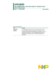
1.1 Outline of synchronous control
"Synchronous control" can be achieved using software instead of controlling mechanically
with gear, shaft, speed change gear or cam etc.
"Synchronous control" synchronizes movement with the input axis (servo input axis,
synchronous encoder axis), by setting "the parameters for synchronous control" and starting
synchronous control on each output axis.
Positioning start
Synchronous
encoder
Synchronous control start
Synchronous control start
Synchronous control start
Manual pulse generator/
Synchronous encoder input
Synchronous encoder
axis parameter
Positioning data
Positioning control
Synchronous encoder
axis
Simple Motion module
Synchronous parameter
Main shaft Composite main Main shaft
shaft gear
main input axis
gear
Servo input axis
parameter
Servo input axis
(Note-1)
Main shaft
clutch
Main shaft
sub input axis
Speed
change
gear (Note-2)
Auxiliary Auxiliary
shaft
shaft Speed change
gear
clutch gear (Note-2)
Composite
auxiliary
shaft gear
Speed
change
gear (Note-2)
Auxiliary
shaft axis
Cam data
Cam
Output axis
Servo
amplifier
Servo
motor
Servo
amplifier
Servo
amplifier
Servo
amplifier
Servo
motor
Servo
motor
Servo
motor
It is possible to control without amplifier
by setting the virtual servo amplifier.
(Note-1): It is possible to drive the servo input axis except the positioning control (OPR, manual control, speed-torque control, synchronous control).
Refer to the "User's Manual (Positioning control)" of each Simple Motion module for details on the positioning control, OPR, the manual
control and the speed-torque control.
(Note-2): Speed change gear can be arranged on one of "Main shaft side", "Auxiliary shaft side" or "After composite auxiliary shaft gear".
1-2
Chapter1 Outline of Synchronous Control
List of synchronous control module
The module is used in synchronous control as follows.
Synchronous parameter
Main shaft module
Input axis module
Main shaft Composite main Main shaft
shaft gear
main input axis
gear
Synchronous encoder
axis parameter
Synchronous encoder
axis
Servo input axis
parameter
Main
shaft
clutch
Main shaft
sub input axis
Servo input axis
Auxiliary Auxiliary
shaft shaft clutch
gear
Composite
auxiliary
shaft gear
Speed
change
gear
Auxiliary shaft axis
Auxiliary shaft module
Speed change
gear module
Cam data
Output axis
module
Cam
Output axis
(1) Input axis
Maximum number of usable
Classification
Name
Parts
Number per module
Function description
QD77MS2
Input axis
module
Servo
input axis
—
• Used to drive the input axis with
the position of the servomotor
controlled by the Simple Motion
module.
Synchronous
encoder axis
—
• Used to drive the input axis with
input pulse from the synchronous
encoder.
1-3
2
Number Reference
QD77MS4 QD77MS16
per axis
LD77MH4 LD77MH16
4
4
16
—
Section 2.1
—
Section 2.2
Chapter1 Outline of Synchronous Control
(2) Output axis
Maximum number of usable
Classification
Name
Parts
Number per module
Function description
QD77MS2
Number Reference
QD77MS4 QD77MS16
per axis
LD77MH4 LD77MH16
Main shaft
main input axis
• The input axis on the main
side of the main shaft
module.
• The reference position on
the main shaft.
2
4
16
1
Section 4.1
Main shaft sub
input axis
• The input axis on the sub
side of the main shaft
module.
• It is used to compensate for
the position of the main shaft
main input axis.
2
4
16
1
Section 4.1
Composite
main shaft gear
• The composite travel value
of the main shaft main input
axis and the main shaft sub
input axis are transmitted to
the main shaft gear.
2
4
16
1
Section 4.1
Main shaft gear
• The converting travel value
after composite main shaft
gear is transmitted by the
setting gear ratio.
2
4
16
1
Section 4.1
Main shaft
clutch
• The main shaft travel value
is transmitted by the clutch
ON/OFF.
2
4
16
1
Section 4.1
Section 4.3
Auxiliary shaft
axis
• The input axis of the auxiliary
shaft module.
2
4
16
1
Section 4.2
Auxiliary shaft
gear
• The converting auxiliary
shaft travel value is
transmitted by the setting
gear ratio.
2
4
16
1
Section 4.2
• The auxiliary shaft travel
value is transmitted by the
clutch ON/OFF.
2
4
16
1
Section 4.2
Section 4.3
• The composite travel value
of the main shaft and the
auxiliary shaft are
transmitted.
2
4
16
1
Section 4.2
Speed change Speed change
gear module gear
• It is used to change the
speed by setting speed
change ratio during the
operation.
2
4
16
1
Section 4.4
Output axis
module
• The cam conversion is
processed based on the
input travel value and the
setting cam data.
• The current feed value is
output as the command to
the servo amplifier.
2
4
16
1
Section 4.5
Main shaft
module
Auxiliary shaft
module
Auxiliary shaft
clutch
Composite
auxiliary shaft
gear
Output axis
1-4
Chapter1 Outline of Synchronous Control
(3) Cam data
Classification
Cam data
Name
Cam data
Function description
• It controls the operation pattern of the output axis
(two-way operation and feed operation), which is
corresponding to the input travel value of the output
axis module.
1-5
Maximum number of usable
Number per module
Up to 256
Reference
Chapter 3
Chapter1 Outline of Synchronous Control
1.2 Performance specifications
Synchronous control performance specifications
Number of settable axes
Item
Input axis
QD77MS2
Servo input axis
2 axes/module
Synchronous encoder axis
QD77MS4
QD77MS16
LD77MH4
LD77MH16
4 axes/module
16 axes/module
4 axes/module
Composite main shaft gear
1/output axis
Main shaft main input axis
1 axis/output axis
Main shaft sub input axis
1 axis/output axis
Main shaft gear
1/output axis
Main shaft clutch
1/output axis
Auxiliary shaft
1 axis/output axis
Auxiliary shaft gear
1/output axis
Auxiliary shaft clutch
1/output axis
Composite auxiliary shaft gear
1/output axis
Speed change gear
1/output axis
Output axis (Cam axis)
2 axes/module
4 axes/module
16 axes/module
Cam specifications
Item
Memory capacity
Specification
Cam storage area
256k bytes
Cam open area
1024k bytes
Up to 256
Number of cam registration
(Note-1)
(Dependent on memory capacity, cam resolution and
coordinate number)
Comment
Up to 32 characters per cam data
Stroke ratio
Cam
data
data format
Coordinate
data format
Cam resolution
256/512/1024/2048/4096/8192/16384/32768
Stroke ratio
-214.7483648 to 214.7483647[%]
Coordinate number
2 to 16384
Input value: 0 to 2147483647
Coordinate data
Output value: -2147483648 to 2147483647
(Note-1): The maximum number of cam registration by the cam resolution is shown below (In case it
created by the same cam resolution).
(1) Stroke ratio data format
(2) Coordinate data format
Cam
resolution
Cam storage area
Maximum number of cam registration
Cam open area
256
256
256
128
256
256
512
128
256
256
128
256
1024
64
256
512
64
256
2048
32
128
1024
32
128
4096
16
64
2048
16
64
8192
8
32
4096
8
32
16384
4
16
8192
4
16
32768
2
8
16384
2
8
1-6
Coordinate Maximum number of cam registration
number
Cam storage area Cam open area
Chapter1 Outline of Synchronous Control
Cam operation specifications
Item
Specification
(1) GX Works2
Operation method of cam data
Write/read/verify to cam storage area
(2) Via buffer memory (Cam data operation function)
Write/read/verify to cam storage area and cam open area
Cam auto-generation function
Automatically generate the cam for rotary cutter.
Calculate the cam position by the sequence program.
Cam position calculation function
Used to calculate the cam position for the synchronous control
initial position before starting synchronous control.
Synchronous encoder axis performance specifications
Item
Specification
Number of control axes
4
Incremental synchronous encoder/
Synchronous encoder axis type
Synchronous encoder via CPU
mm, inch, degree, PLS
Control unit
(Possible to select the decimal places of
position unit and speed unit)
Unit
conversion
-2147483648 to 2147483647
Numerator
[Synchronous encoder axis position unit]
1 to 2147483647
Denominator
[PLS]
1 to 2147483647
Length per cycle setting range
Current
value range
[Synchronous encoder axis position unit]
-2147483648 to 2147483647
Current value
[Synchronous encoder axis position unit]
Current value
0 to (Length per cycle - 1)
per cycle
Control
method
Control instruction
Current value
[Synchronous encoder axis position unit]
Current value change, Counter disable, Counter enable
Address setting range: -2147483648 to 2147483647
setting address
[Synchronous encoder axis position unit]
1-7
Chapter1 Outline of Synchronous Control
1.3 Restrictions by the SERIAL No. and version
There are restrictions in the function that can be used by the version of the SERIAL No. and
software of the Simple Motion module.
The combination of each version and function are shown below.
(1) LD77MH
LD77MH4
Function
First five digits of
SERIAL NO.
LD77MH16
(Note-1)
MELSOFT
GX Works2
Clutch function
12102 or later
Auxiliary shaft
First five digits of
SERIAL NO.
Reference
(Note-1)
MELSOFT
GX Works2
1.48A or later
—
1.48A or later
Section 4.1
Section 4.2
Section 4.3
12102 or later
1.48A or later
—
1.48A or later
Section 4.2
Cam function using coordinate data
format
12102 or later
1.48A or later
—
1.48A or later
Chapter 3
Expand capacity of cam storage area
(16k bytes to 256k bytes)
12102 or later
1.48A or later
—
1.48A or later
Section 1.2
Synchronous control change function
12102 or later
1.48A or later
—
1.48A or later
Section 4.6
Synchronous encoder: 4 axes
12102 or later
1.48A or later
—
1.48A or later
Section 2.2
Synchronous encoder via CPU
12102 or later
1.48A or later
—
1.48A or later
Section 2.2
Synchronous encoder control by
high speed input request
12102 or later
1.48A or later
—
1.48A or later
Section 2.2
Output axis smoothing function
12102 or later
1.48A or later
12102 or later
1.48A or later
Section 4.5
Cam axis current value per cycle
movement function
12102 or later
—
12102 or later
—
Section 4.6
—: No restriction by the version.
(Note-1): The serial number can be checked on the "Product Information List" screen in GX Works2.
Refer to the following for how to check the SERIAL No. of the Simple Motion module.
• QD77MS : "MELSEC-Q QD77MS Simple Motion Module User's Manual (Positioning
Control)"
• LD77MH : "MELSEC-L CPU Module User's Manual (Hardware Design, Maintenance and
Inspection)"
1-8
Chapter1 Outline of Synchronous Control
1.4 General configuration of buffer memory (Synchronous control area)
Buffer memory address
QD77MS2
QD77MS4 QD77MS16
LD77MH4
LD77MH16
Number of
32800
to
160
32959
33120
to
160
33279
34720
to
80
34799
35040
to
40
35079
35200
to
Item
word
80
35279
Servo input axis parameter
(10 words/axis)
Servo input axis monitor data
(10 words/axis)
Synchronous encoder axis parameter
(20 words/axis)
Synchronous encoder axis control data
(10 words/axis)
Synchronous encoder axis monitor data
(20 words/axis)
Pr.300 to Pr.304
Md.300 to Md.303
Pr.320 to Pr.329
Cd.320 to Cd.325
Md.320 to Md.327
36320
to
40
Synchronous control system control data
Cd.380 to Cd.381
36359
36400
to
3200
39599
42800
to
640
43439
44080
to
320
44399
Synchronous parameter
(200 words/axis)
Synchronous control monitor data
(40 words/axis)
Control data for synchronous control
(20 words/axis)
Pr.400 to Pr.468
Md.400 to Md.425
Cd.400 to Cd.409
45000
to
8800
Cam operation control data
Cd.600 to Cd.618
200
Cam operation monitor data
Md.600
53799
53800
to
53999
1-9
Chapter1 Outline of Synchronous Control
1.5 Operation method of synchronous control
1.5.1 Synchronous control execution procedure
The synchronous control is executed using the following procedure.
Preparation
STEP 1
Refer to Section
1.5.2.
Refer to Chapter 2
Set "input axis parameters" for synchronous
control .
( Pr.300 to Pr.304 , Pr.320 to Pr.329 )
Refer to Chapter 3
Set the cam data.
Refer to Chapter 4
and Section 5.2
Set "synchronous parameters" for synchronous
control .
( Pr.400 to Pr.468 )
STEP 2
Refer to
Appendices
Start
synchronous
control
Set "positioning parameters".
( Pr.1 to Pr.42 , Pr.80 to Pr.84 , Pr.89 ,
Pr.90 , Pr.95 )
One of the following two methods can be used.
<Method 1>
Directly set (write) the parameters in the Simple Motion
module using GX Works2.
<Method 2>
Set (write) the parameters from the PLC CPU to
the Simple Motion module using the sequence program
(TO command).
Create a sequence program that executes to
start / change control / stop synchronous
control.
(Set " Cd.380 Synchronous control start",
start and stop the input axis operation and
change the reduction ratio)
STEP 3
Write the sequence program, which is created
in STEP1 and STEP2, to the PLC CPU.
STEP 4
Turn ON the bit of the synchronous control start
that start synchronous control.
Turn ON the target axis bit in
" Cd.380 Synchronous control start" and start
synchronous control by the sequence program in STEP 2.
Verify that it's during synchronous control.
Verify that it's during synchronous control in
" Md.26 Axis operation status ".
Operate the input axis by the sequence program in STEP 2.
Operate the input axis.
Monitor the
synchronous
control change
STEP 5
Complete
synchronous
control
STEP 6
Monitor the synchronous control operation
status.
Execute the control change for the speed
change ratio or cam No. etc.
Monitor using GX Works2.
Changing the control by the sequence program in STEP 2.
Stop the input axis by the sequence program in STEP 2.
Stop the input axis.
Verify the input axis is stopped and turn OFF
the bit of the synchronous control start that
stop synchronous control.
Turn OFF the target axis bit in
" Cd.380 Synchronous control start" to stop synchronous
control by the sequence program in STEP 2.
End of control
REMARK
• Mechanical elements such as limit switches are considered as already installed.
• Parameter settings for positioning control apply for all axes with the Simple Motion
module.
• Be sure to execute the OPR when the OPR request flag is ON.
1 - 10
Chapter1 Outline of Synchronous Control
1.5.2 Setting items for positioning parameters
The setting items for the positioning parameters for synchronous control are shown below.
Positioning parameter setting applies for each axis of control with the Simple Motion module.
Refer to the "User's Manual (Positioning control)" of each Simple Motion module for details
on the setting items.
Control
Positioning parameter
Basic
parameters 1
Basic
parameters 2
Detailed
parameters 1
Synchronous
control
Pr.1
Unit setting
Pr.2
Number of pulses per rotation (AP) (Unit: PLS)
Pr.3
Movement amount per rotation (AL)
Pr.4
Unit magnification (AM)
Pr.7
Bias speed at start
Pr.8
Speed limit value
Pr.9
Acceleration time 0
—
Pr.10
Deceleration time 0
—
Pr.11
Backlash compensation amount
Pr.12
Software stroke limit upper limit value
Pr.13
Software stroke limit lower limit value
Pr.14
Software stroke limit selection
Pr.15
Software stroke limit valid/invalid setting
—
Pr.16
Command in-position width
—
Pr.17
Torque limit setting value
Pr.18
M code ON signal output timing
—
Pr.19
Speed switching mode
—
Pr.20
Interpolation speed designation method
—
Pr.21
Current feed value during speed control
—
Pr.22
Input signal logic selection
Pr.24
—
Manual pulse generator/Incremental synchronous
encoder input selection
Pr.80
External input signal selection
Pr.81
Speed-position function selection
Pr.82
Forced stop valid/invalid selection
—
: Always set
: Set as required ("—" when not required)
— : Setting not required (This is an irrelevant item, so the setting value will be ignored. If the value is the
default value or within the setting range, there is no problem.)
1 - 11
Chapter1 Outline of Synchronous Control
Control
Positioning parameter
Synchronous
control
Pr.25
Acceleration time 1
—
Pr.26
Acceleration time 2
—
Pr.27
Acceleration time 3
—
Pr.28
Deceleration time 1
—
Pr.29
Deceleration time 2
—
Pr.30
Deceleration time 3
—
Pr.31
JOG speed limit value
—
Pr.32
JOG operation acceleration time selection
—
Pr.33
JOG operation deceleration time selection
—
Pr.34
Acceleration/deceleration process selection
Pr.35
S-curve ratio
Detailed
Pr.36
Sudden stop deceleration time
parameters 2
Pr.37
Stop group 1 sudden stop selection
Pr.38
Stop group 2 sudden stop selection
Pr.39
Stop group 3 sudden stop selection
Pr.40
Positioning complete signal output time
—
Pr.41
Allowable circular interpolation error width
—
Pr.42
External command function selection
Pr.83
Speed control 10 x multiplier setting for degree axis
Pr.84
Restart allowable range when servo OFF to ON
Pr.89
—
Manual pulse generator/Incremental synchronous
encoder input type selection
Pr.90
Operation setting for speed-torque control mode
Pr.95
External command signal selection
—
: Always set
: Set as required ("—" when not required)
— : Setting not required (This is an irrelevant item, so the setting value will be ignored. If the value is the
default value or within the setting range, there is no problem.)
1 - 12
Chapter1 Outline of Synchronous Control
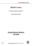
1.5.3 Starting/ending for synchronous control
Set the parameters for synchronous control for each output axis to start synchronous control.
The status changes to synchronous control after the parameters are analyzed at the start of
synchronous control, and the output axes synchronize with input axis operations.
Cd.380 Synchronous control
start (Target axis bit)
BUSY signal
Md.26 Axis operation status
Standby (0)
Analyzing (5)
Synchronous control (15)
Standby (0)
Md.321 Synchronous encoder
axis current value per
cycle
t
Md.407 Cam axis current value
per cycle
t
Md.20 Current feed value
t
Synchronous control system control data
Setting item
Setting details
• Synchronous control begins if the target
axis bit is turned ON.
•
Synchronous control Synchronous control ends if the bit is
turned OFF during synchronous control.
start
Fetch cycle: Operation cycle
Cd.380
Setting value
Set the target axis in 16bits.
(Note-1)
)
(bit0: axis 1 to bit15: axis 16
OFF : Synchronous control end
ON : Synchronous control start
Default
value
Buffer memory
address
0
36320
(Note-1): The range from axis 1 to 2 is valid in the QD77MS2, and the range from axis 1 to 4 is valid in the QD77MS4/LD77MH4.
Starting method for synchronous control
Synchronous control can be started by turning the target axis bit from OFF to ON in
" Cd.380 Synchronous control start" after setting the parameters for synchronous control.
"5: Analyzing" is set in " Md.26 Axis operation status" at the synchronous control start, and
the parameters for synchronous control are analyzed. The BUSY signal turns ON after
completion of analysis, and "15: Synchronous control" is set in " Md.26 Axis operation status".
Start the input axis operation after confirming that "15: Synchronous control" is set in
" Md.26 Axis operation status".
1 - 13
Chapter1 Outline of Synchronous Control
Ending method for synchronous control
Synchronous control can be ended by turning the target axis bit from ON to OFF in
" Cd.380 Synchronous control start" after the input axis operation is stopped.
The BUSY signal turns OFF at the synchronous control end, and "0: Standby" is set in
" Md.26 Axis operation status".
Synchronous control can also be ended by turning the target axis bit from ON to OFF in
" Cd.380 Synchronous control start" during the input axis operation. However, it is
recommended to end after stopping the input axis operation since the output axis stops
immediately.
Refer to Section 1.5.4 "Stop operation of output axis" at the synchronous control end.
Starting history
The starting history is updated when starting synchronous control. "9020: Synchronous
control operation" is stored in " Md.4 Start No.".
Status when starting synchronous control
The following bits in " Md.31 Status" are turned OFF when starting synchronous control in
the same way as for the positioning control start.
b0 : In speed control flag
b1 : Speed-position switching latch flag
b2 : Command in-position flag
b4 : OPR complete flag
b5 : Position-speed switching latch flag
b10 : Speed change 0 flag
Restrictions
(1) If bit for multiple axes are turned ON simultaneously in " Cd.380 Synchronous control
start", control is not started simultaneously since the analysis is processed for each
axis in numerical order. When the multiple axes must be started simultaneously, start
the input axis operation after confirming that all axes are configured for the
synchronous control.
(2) If the input axis operates during the analysis at the synchronous control start, the
travel value of the input axis is reflected immediately after the synchronous control
start. The output axis might suddenly accelerate depending on the travel value of the
input axis. Start the input axis operation after confirming that are configured for
synchronous control.
(3) The analysis process for synchronous control start might take time depending on the
parameter setting for synchronous control. (Up to 16 ms: In case of searching the cam
(cam resolution: 32768) with the setting "0: Cam axis current value per cycle
restoration" in " Pr.462 Cam axis position restoration object".)
Set "1: Cam reference position restoration" or "2: Cam axis current feed value
restoration" in " Pr.462 Cam axis position restoration object" to start synchronous control at
high speed.
1 - 14
Chapter1 Outline of Synchronous Control
1.5.4 Stop operation of output axis
If the following causes occur in stopping the output axis during synchronous control,
synchronous control is completed after stops processing for the output axis (BUSY signal is
OFF, axis operation status is standby).
Synchronous alignment must be executed for the output axis to restart control.
(Refer to Section 4.5)
Stop cause
The target axis bit of "
Cd.380 Synchronous control start"
Stop process
is turned from ON to OFF.
Immediate stop
Software stroke limit error occurrence
Forced stop
Stop group1 to 3
(Note-1)
(Stop with hardware stroke limit or stop command)
Deceleration stop
(Note-1): Refer to the "User's Manual (Positioning control)" of each Simple Motion module.
(1) Immediate stop
The operation stops without decelerate. The Simple Motion module immediately stops
the command, but the operation will coast for the droop pulses accumulated in the
deviation counter of the servo amplifier.
Md.407 Cam axis current
value per cycle
t
Md.20 Current feed value
(Cam operation)
t
Md.22 Feedrate
t
Immediate stop
Cd.380 Synchronous control
start (Target axis bit)
BUSY signal
1 - 15
Chapter1 Outline of Synchronous Control
(2) Deceleration stop
The output axis stops with deceleration according to the setting in " Pr.37 Stop group 1
sudden stop selection" to " Pr.39 Stop group 3 sudden stop selection". The deceleration time
is set in " Pr.446 Synchronous control deceleration time" for deceleration stop, and in " Pr.36
Sudden stop deceleration time" for sudden stop. The slope of deceleration is as follows.
Slope of deceleration
=
"
Pr.8 Sped limit value"
/
Deceleration time
(Sudden stop deceleration time)
The cam axis current value per cycle is not updated, and only the current feed value is
updated, since the deceleration stop begins. Therefore, the path of the current feed
value is drawn regardless the cam operation with deceleration stop.
The input axis must be stopped when the output axis is stop synchronizing with the
input axis.
Md.407 Cam axis current
value per cycle
t
Md.20 Current feed value
(Cam operation)
t
Md.22 Feedrate
t
Deceleration stop
Cd.380 Synchronous control
start (Target axis bit)
Axis stop signal
BUSY signal
1 - 16
Chapter 2 Input Axis Module
Chapter 2 Input Axis Module
The settings for the parameter and monitor data for the input axis module that
used with synchronous control are explained in this chapter.
Refer to the "User's Manual (Positioning Control)" of each Simple Motion module
for details on the connection and control for the servo amplifier and the synchronous
encoder that used for input axis module.
2.1 Servo input axis.......................................................................................................2- 2
2.1.1 Overview of servo input axis ..........................................................................2- 2
2.1.2 Servo input axis parameters ..........................................................................2- 4
2.1.3 Servo input axis monitor data ........................................................................2- 8
2.2 Synchronous encoder axis......................................................................................2-10
2.2.1 Overview of synchronous encoder axis .........................................................2-10
2.2.2 Setting method for synchronous encoder ......................................................2-13
2.2.3 Synchronous encoder axis parameters .........................................................2-17
2.2.4 Synchronous encoder axis control data.........................................................2-24
2.2.5 Synchronous encoder axis monitor data .......................................................2-28
2-1
2
Chapter 2 Input Axis Module
2.1 Servo input axis
2.1.1 Overview of servo input axis
The servo input axis is used to drive the input axis based on the position of the servomotor
that is being controlled by the Simple Motion module.
The status of a servo input axis can also be monitored after the system's power supply turns
ON.
The following shows the relationship between the position of the servomotor and the servo
input axis.
Pr.300 Servo input
axis type
Servo motor position
Current feed value
Real current value
Servo command value
Feedback value
Input
smoothing
processing
Pr.301 Servo input axis
smoothing time
constant
Pr.302 Servo input axis
phase compensation
advance time
Pr.303 Servo input axis
phase compensation
time constant
Phase
compensation
processing
Pr.304 Servo input axis
rotation direction
restriction
Rotation direction
restriction
Current value of
servo input axis
Md.302 Servo input axis
phase compensation
amount
Md.303 Servo input axis
rotation direction
restriction amount
Md.300 Servo input axis
current value
Md.301 Servo input axis
speed
Control method for servo input axis
All controls (including synchronous control) can be executed for a servo input axis.
Refer to the "User's Manual (Positioning Control)" of each Simple Motion module for the
controls other than synchronous control.
POINT
If the virtual servo amplifier function is set in the servo input axis, synchronous control
can be executed by the input value as virtual.
Refer to the "User's Manual (Positioning Control)" of each Simple Motion module for
details on virtual servo amplifier function.
2-2
Chapter 2 Input Axis Module
Restrictions
If "1: Current feed value" or "2: Real current value" is set in " Pr.300 Servo input axis type", set
"1: Update current feed value" in " Pr.21 Current feed value during speed control" to start the
speed position change control. If "0: Do not update current feed value" or "2: Clear current
feed value to zero" is set in Pr.21 , "Speed-position switching control start in servo input
axis not possible (error code: 609)" will occur and the control will not start.
Units for the servo input axis
The position units and speed units for the servo input axis are shown below for the setting
" Pr.300 Servo input axis type" and " Pr.1 Unit setting".
Table 2.1 Servo input axis position units
Setting value of "
Pr.300
Servo input axis type"
Setting value of
" Pr.1 Unit setting"
Servo input axis
position unit
-4
1: Current feed value
2: Real current value
0: mm
10 mm
-1
(10 μm)
1: inch
10 inch
-5
-21474.83648 to 21474.83647 [inch]
10 degree
3: PLS
3: Servo command value
4: Feedback value
-214748.3648 to 214748.3647 [mm]
(-214748364.8 to 214748364.7 [μm])
-5
2: degree
—
Range
-21474.83648 to 21474.83647 [degree]
PLS
-2147483648 to 2147483647 [PLS]
PLS
-2147483648 to 2147483647 [PLS]
Table 2.2 Servo input axis speed units
Setting value of "
Pr.300
Servo input axis type"
1: Current feed value
2: Real current value
Setting value of
" Pr.1 Unit setting"
-2
0: mm
10 mm/min
1: inch
10 inch/min
-3
2: degree
3: PLS
3: Servo command value
4: Feedback value
Servo input axis
speed unit
—
-3
10 degree/min
(Note-1)
Range
-21474836.48 to 21474836.47 [mm/min]
-2147483.648 to 2147483.647 [inch/min]
-2147483.648 to 2147483.647 [degree/min]
PLS/s
-2147483648 to 2147483647 [PLS/s]
PLS/s
-2147483648 to 2147483647 [PLS/s]
-2
(Note-1)
(Noet-1): When " Pr.83 Speed control 10 x multiplier setting for degree axis" is valid, this will be the speed unit " 10 degree/min"
(Range: -21474836.48 to 21474836.47 [degree/min]).
2-3
Chapter 2 Input Axis Module
2.1.2 Servo input axis parameters
Setting item
Pr.300
Servo input axis type
Default
value
Buffer memory
address
Set in decimal.
0: Invalid
1: Current feed value
2: Real current value
3: Servo command value
4: Feedback value
0
32800+10n
Set in decimal.
0 to 5000 [ms]
0
32801+10n
• Set the time to advance or delay the
phase.
Fetch cycle: Operation cycle
Set in decimal.
-2147483648 to 2147483647 [μs]
0
32802+10n
32803+10n
• Set the time constant to affect the phase
compensation.
Fetch cycle: At power supply ON
Set in decimal.
(Note-1)
0 to 65535 [ms]
10
32804+10n
Set in decimal.
0: Without rotation direction restriction
1: Enable only for current value
increase direction
2: Enable only for current value
decrease direction
0
32805+10n
Setting details
Setting value
• Set the current value type to be
generated of the input value for the
servo input axis.
Fetch cycle: At power supply ON
Pr.301
• Set to smooth the input value.
Servo input axis
Fetch cycle: At power supply ON
smoothing time constant
Pr.302
Servo input axis
phase compensation
advance time
Pr.303
Servo input axis
phase compensation
time constant
• Set this parameter to restrict the input
travel value to one direction.
Servo input axis rotation
Fetch
cycle: At power supply ON
direction restriction
Pr.304
n: Axis No.-1
(Note-1): Set the value as follows in a sequence program.
0 to 32767 ................... Set as a decimal.
32768 to 65535 ........... Convert into a hexadecimal and set.
2-4
Chapter 2 Input Axis Module
Pr.300 Servo input axis type
Set the current value type to be generated of the input value for the servo input axis.
0: Invalid.................................... Servo input axis is invalid.
1: Current feed value ................ Generate the input value based on " Md.20 Current feed
value".
2: Real current value................. Generate the input value based on the real current value,
which is converted units of the encoder feedback pulses
from the servo amplifier.
3: Servo command value.......... Generate the input value based on the command pulse
(encoder pulse units) to the servo amplifier.
4: Feedback value .................... Generate the input value based on the encoder feedback
pulse from the servo amplifier.
Simple Motion module
1: Current feed value
Unit Pulse
conversion
3: Servo command value
2: Real current value
Pulse Unit
conversion
4: Feedback value
Servo
amplifier
Pr.301 Servo input axis smoothing time constant
Set the averaging time to execute a smoothing process for the input travel value from the
servo input axis.
The smoothing process can moderate speed fluctuation, when the "Real current value" or
"Feedback value" is used as input values.
The input response is delayed depending on the time corresponding to the setting by
smoothing process setting.
Input value speed
before smoothing
Averaging by
smoothing time constant
Input value speed
after smoothing
t
t
Pr.301 Servo input axis
smoothing time constant
2-5
Pr.301 Servo input axis
smoothing time constant
Chapter 2 Input Axis Module
Pr.302 Servo input axis phase compensation advance time
Set the time to advance or delay the phase (input response) of the servo input axis.
Refer to Section 4.8 "Phase compensation function" for the peculiar time delay of the
system using the servo input axis.
1 to 2147483647 [μs]............... Advance the phase (input response) according to the
setting time.
0 [μs] ........................................ Do not execute phase compensation.
-2147483648 to -1 [μs] ............ Delay the phase (input response) according to the setting
time.
If the setting time is too long, the system experiences overshoot or undershoot at
acceleration/deceleration of the input speed. In this case, set longer time to affect the
phase compensation amount in " Pr.303 Servo input axis phase compensation time constant".
Pr.303 Servo input axis phase compensation time constant
Set the time constant to affect the phase compensation amount for the first order delay.
63 [%] of the phase compensation amount are reflected in the time constant setting.
Pr.302 Servo input axis
phase compensation
advance time
Servo input axis
current value
Current value after phase compensation
Current value before phase compensation
t
Speed before phase
compensation
t
Speed after phase
compensation
t
Md.302 Servo input axis
phase compensation
amount
Speed before phase
compensation
Pr.302 Servo input axis phase
compensation advance time
63%
63%
t
Pr.303 Servo input axis phase
compensation time constant
2-6
Pr.303 Servo input axis phase
compensation time constant
Chapter 2 Input Axis Module
Pr.304 Servo input axis rotation direction restriction
Set this parameter to restrict the input travel value for the servo input axis to one direction.
This helps to avoid reverse operation caused by machine vibration, etc. when "Real
current value" or "Feedback value" is used as input values.
0: Without rotation direction restriction................................Rotation direction restriction is
not executed.
1: Enable only for current value increase direction .............Enable only the input travel
value in the increasing direction
of the servo input axis current
value.
2: Enable only for current value decrease direction............Enable only the input travel
value in the decreasing
direction of the servo input axis
current value.
The input travel value in the opposite direction of the enable direction accumulates as a
rotation direction restricted amount, and will be reflected when the input travel value
moves in the enabled direction again. Therefore, the current value of servo input does not
deviate when the reverse operation is repeated.
The rotation direction restricted amount is set to 0 when the following operations are
executed for the servo input axis.
• A servo amplifier is connected
• A OPR is executed
• The current value is changed
For "1: Enable only for current value increase direction" is
set in " Pr.304 Servo input axis rotation direction restriction".
Speed before rotation
direction restriction
t
Md.301 Servo input axis speed
(Speed after rotation
direction restriction)
t
Md.303 Servo input axis
rotation direction
restriction amount
t
The input travel value is accumulated as a rotation
direction restricted amount, and will be reflected when
the input travel moves in the ebable direction.
2-7
Chapter 2 Input Axis Module
2.1.3 Servo input axis monitor data
Monitor item
Storage details
Reading the monitor value
Buffer memory
address
• The current value for the servo input axis is
stored.
Refresh cycle: Operation cycle
Monitoring is carried out in decimal.
-2147483648 to 2147483647
(Note-1)
[Servo input axis position units
]
33120+10n
33121+10n
• The speed for the servo input axis is stored.
Refresh cycle: Operation cycle
Monitoring is carried out in decimal.
-2147483648 to 2147483647
(Note-2)
[Servo input axis speed units
]
33122+10n
33123+10n
• The current phase compensation amount is
stored.
Refresh cycle: Operation cycle
Monitoring is carried out in decimal.
-2147483648 to 2147483647
(Note-1)
[Servo input axis position units
]
33124+10n
33125+10n
• While the rotation direction is restricted, the
accumulation for the input travel value in the
Servo input axis rotation
opposite direction of the enable direction is
direction restriction
stored.
amount
Refresh cycle: Operation cycle
Monitoring is carried out in decimal.
-2147483648 to 2147483647
(Note-1)
[Servo input axis position units
]
33126+10n
33127+10n
Md.300
Servo input axis current
value
Md.301
Servo input axis speed
Md.302
Servo input axis phase
compensation amount
Md.303
n: Axis No.-1
(Note-1): Servo input axis position units (Refer to Section 2.1.1)
(Note-2): Servo input axis speed units (Refer to Section 2.1.1)
Md.300 Servo input axis current value
The current value for the servo input axis is stored in servo input axis position units (Refer
to Section 2.1.1) as follows.
The current value for the servo input axis is the value after processing the smoothing, the
phase compensation and the rotation direction restriction.
Setting value of "
Pr.300
Storage details
Servo input axis type"
1: Current feed value
2: Real current value
• The accumulative current value started with " Md.20 Current feed value"/" Md.101
Real current value" for the connection to the servo amplifier is stored. It is also
stored in the range from -21474.83648 to 21474.83647 [degree] for degree units.
• When the " Md.20 Current feed value"/" Md.101 Real current value" is changed by an
OPR or a current value change, the value is changed to the new current value.
3: Servo command value
4: Feedback value
• When of the absolute position detection system setting is invalid, the
accumulative current value that starts from 0 for the connected servo amplifier is
stored.
• When of the absolute position detection system setting is valid, the accumulative
current value that starts from the absolute position command/encoder feedback
pulse for the connected servo amplifier is stored.
• The servo input axis current value will not change, even if an OPR or the current
value is changed.
2-8
Chapter 2 Input Axis Module
Md.301 Servo input axis speed
The speed for the servo input axis is stored in servo input axis speed units (Refer to
Section 2.1.1).
The speed for the servo input axis is the value after processing smoothing, phase
compensation, and rotation direction restriction.
Md.302 Servo input axis phase compensation amount
The phase compensation amount for a servo input axis is stored in servo input axis
position units (Refer to Section 2.1.1).
The phase compensation amount for a servo input axis is the value after processing
smoothing and phase compensation.
Md.303 Servo input axis rotation direction restriction amount
While the rotation direction is restricted for a servo input axis, the accumulation for input
travel value in the opposite direction of the enabled direction is stored in servo input axis
position units (Refer to Section 2.1.1) as follows.
Setting value of "
Pr.304 Servo input
Storage details
axis rotation direction restriction"
1: Enable only for current value
increase direction
A negative accumulation is stored during rotation direction restriction.
0 is stored if there is no restriction.
2: Enable only for current value
decrease direction
A positive accumulation is stored during rotation direction restriction.
0 is stored if there is no restriction.
Rotation direction restriction is processed after phase compensation processing.
Therefore, if undershoot occurs from phase compensation during deceleration stop, the
rotation direction restriction amount might remain.
2-9
Chapter 2 Input Axis Module
2.2 Synchronous encoder axis
2.2.1 Overview of synchronous encoder axis
The synchronous encoder is used to drive the input axis based on input pulse from a
synchronous encoder that is connected externally.
The status of a synchronous encoder axis can also be monitored after the system's power
supply turns ON.
Pr.22 Input signal logic selection
Pr.24 Manual pulse generator/
Incremental synchronous
encoder input selection
Pr.89 Manual pulse generator/
Incremental synchronous
encoder input type selection
Pr.320 Synchronous encoder
axis type
Input pulse
of synchronous
encoder
Counter disable/
Counter enable
Pr.321 Synchronous encoder
axis unit setting
Pr.322 Synchronous encoder
axis unit conversion:
Numerator
Pr.323 Synchronous encoder
axis unit conversion:
Denominator
Unit conversion
Pr.325 Synchronous encoder
axis smoothing time
constant
Input smoothing
processing
Pr.326 Synchronous encoder
axis phase compensation
advance time
Pr.327 Synchronous encoder
axis phase compensation
time constant
Pr.328 Synchronous encoder
axis rotation direction
restriction
Phase
compensation
processing
Rotation
direction
restriction
Current value change
Pr.324 Synchronous encoder
axis length per cycle
Current value
of synchronous
encoder axis
2 - 10
Md.323 Synchronous encoder axis
phase compensation amount
Md.324 Synchronous encoder axis
rotation direction restriction
amount
Md.320 Synchronous encoder axis
current value
Md.321 Synchronous encoder axis
current value per cycle
Md.322 Synchronous encoder
axis speed
Chapter 2 Input Axis Module
Synchronous encoder axis type
The following 3 types of synchronous encoders can be used for the synchronous encoder
axis.
Refer to Section 2.2.2 for the setting method for each synchronous encoder axis.
Synchronous encoder
axis type
Details
Incremental synchronous
encoder
The incremental synchronous encoder that is connected to the manual pulse
generator/incremental synchronous encoder input of the Simple Motion module is
used as the synchronous encoder axis.
Synchronous encoder via
CPU
Used to operate a gray code encoder that is connected to the input module of PLC
CPU as a synchronous encoder axis.
Control method for synchronous encoder axis
The following controls can be executed for the synchronous encoder axis by using
" Cd.320 Synchronous encoder axis control start" and " Cd.321 Synchronous encoder axis control
method".
Setting value of "
Cd.321
Control details
Synchronous encoder axis
control method"
"
0: Current value change
Md.320 Synchronous encoder axis current value"
and "
Md.321 Synchronous encoder axis
current value per cycle" are changed based on the setting of " Cd.322 Synchronous
encoder axis current value setting address".
1: Counter disable
Input from the synchronous encoder is disabled.
2: Counter enable
Input from the synchronous encoder is enabled.
2 - 11
Chapter 2 Input Axis Module
Units for the synchronous encoder axis
The position units and speed units for the synchronous encoder axis are shown below for
the setting of " Pr.321 Synchronous encoder axis unit setting".
Table 2.3 Synchronous encoder axis position units
Setting value of
"
Pr.321 Synchronous encoder axis unit setting"
Number of decimal
places for position
Control unit
Synchronous encoder
axis position unit
Range
mm
-2147483648 to 2147483647 [mm]
0
0: mm
-9
10 mm
9
0
inch
-2.147483648 to 2.147483647 [mm]
-2147483648 to 2147483647 [inch]
1: inch
-9
9
10 inch
0
degree
-2.147483648 to 2.147483647 [inch]
-2147483648 to 2147483647 [degree]
2: degree
-9
10 degree
9
0
PLS
-2.147483648 to 2.147483647 [degree]
-2147483648 to 2147483647 [PLS]
3: PLS
-9
10 PLS
9
-2.147483648 to 2.147483647 [PLS]
Table 2.4 Synchronous encoder axis speed units
Setting value of
"
Pr.321 Synchronous encoder axis unit setting"
Control unit
Speed time unit
Number of decimal
places for speed
Synchronous encoder
axis speed unit
Range
mm/s
-2147483648 to 2147483647 [mm/s]
0
0: sec
0: mm
-9
9
10 mm/s
-2.147483648 to 2.147483647 [mm/s]
0
mm/min
-2147483648 to 2147483647 [mm/min]
1: min
-9
10 mm/min
9
0
inch/s
-2.147483648 to 2.147483647 [mm/min]
-2147483648 to 2147483647 [inch/s]
0: sec
1: inch
-9
9
10 inch/s
-2.147483648 to 2.147483647 [inch/s]
0
inch/min
-2147483648 to 2147483647 [inch/min]
1: min
-9
10 inch/min
9
0
degree/s
-2.147483648 to 2.147483647 [inch/min]
-2147483648 to 2147483647 [degree/s]
0: sec
2: degree
-9
9
10 degree/s
-2.147483648 to 2.147483647 [degree/s]
0
degree/min
-2147483648 to 2147483647 [degree/min]
1: min
9
-9
10 degree/min
0
PLS/s
-2.147483648 to 2.147483647 [degree/min]
-2147483648 to 2147483647 [PLS/s]
0: sec
3: PLS
-9
9
10 PLS/s
-2.147483648 to 2.147483647 [PLS/s]
0
PLS/min
-2147483648 to 2147483647 [PLS/min]
1: min
-9
10 PLS/min
9
2 - 12
-2.147483648 to 2.147483647 [PLS/min]
Chapter 2 Input Axis Module
2.2.2 Setting method for synchronous encoder
[1] Incremental synchronous encoder
Setting method
Connect the synchronous encoder to the "Manual pulse generator/Incremental
synchronous encoder input" of the Simple Motion module.
Set the input method for the incremental synchronous encoder signal using the following
parameters. (It may be common to use the same set up for the manual pulse generator
input.)
• " Pr.22 Input signal logic selection"
• " Pr.24 Manual pulse generator/Incremental synchronous encoder input selection"
• " Pr.89 Manual pulse generator/Incremental synchronous encoder input type selection"
POINT
The synchronous encoder axis operates completely independently with the manual
pulse generator operation.
The parameter and control data for the manual pulse generator operation except
the 3 parameters listed above has not influence on control of synchronous encoder
axis. Therefore, they can also be controlled simultaneously by common input
pulses.
When the synchronous encoder axis connection is valid after the system's power supply is
ON, it will be "Synchronous encoder axis current value=0", "Synchronous encoder axis
current value per cycle=0" and "Counter enabling status".
2 - 13
Chapter 2 Input Axis Module
Setting example
The following shows an example for setting an incremental synchronous encoder as
synchronous encoder axis 2 of the QD77MS.
QD77MS
Incremental
synchronous
encoder
Synchronous encoder axis 2
Axis 1
Axis 2
Axis 3
Set "1: Incremental synchronous encoder" in " Pr.320 Synchronous encoder axis type" for the
synchronous encoder axis 2.
And, set the input method for incremental synchronous encoder signal in the following
parameters.
• " Pr.22 Input signal logic selection" Manual pulse generator input (b8)
................................................................... "0: Negative logic"
• " Pr.24 Manual pulse generator/Incremental synchronous encoder input selection"
.......................................................................... "0: A-phase/B-phase multiplied by 4"
• " Pr.89 Manual pulse generator/Incremental synchronous encoder input type selection"
................................................................... "0: Differential output type"
2 - 14
Chapter 2 Input Axis Module
[2] Synchronous encoder via CPU (Synchronous encoder via PLC CPU)
Setting method
Used to operate a gray code encoder that is connected to the input module of the PLC
CPU as a synchronous encoder axis.
By setting "201: Synchronous encoder via CPU" in " Pr.320 Synchronous encoder axis type",
the synchronous encoder is controlled by the encoder value which is the input value of
" Cd.325 Input value for synchronous encoder via CPU".
The encoder value can be used as a cycle counter within the range from 0 to (Resolution
of synchronous encoder via CPU - 1).
Connection is invalid just after the system's power supply is ON. When "1" is set in
" Cd.324 Connection command of synchronous encoder via CPU", the synchronous encoder axis
current value and the synchronous encoder axis current value per cycle are restored
based on " Cd.325 Input value for synchronous encoder via CPU". Therefore, connection
becomes valid, and will be on the counter enabling status.
The synchronous encoder axis is controlled based on the amount of change of " Cd.325
Input value for synchronous encoder via CPU" while it is connecting.
Setting example
The following shows an example for setting a synchronous encoder via CPU as
synchronous encoder axis 4 of the QD77MS.
QD77MS
Input
module
Gray code encoder
(Resolution 4096)
Synchronous encoder axis 4
Axis 1
Axis 2
Axis 3
Set "201: Synchronous encoder via CPU" in " Pr.320 Synchronous encoder axis type" of
synchronous encoder axis 4.
Set "4096" in " Pr.329 Resolution of synchronous encoder via CPU" of synchronous
encoder axis 4.
Read the encoder value of the gray code encoder with a sequence program, and update
" Cd.325 Input value for synchronous encoder via CPU" of the synchronous encoder axis 4 at
every time.
2 - 15
Chapter 2 Input Axis Module
Restrictions
(1) " Cd.325 Input value for synchronous encoder via CPU" is taken every operation cycle, but
it is asynchronous with the scan time of the PLC CPU. Therefore, speed fluctuation of
the synchronous encoder axis becomes larger if the refresh cycle of " Cd.325 Input
value for synchronous encoder via CPU" becomes long.
Update " Cd.325 Input value for synchronous encoder via CPU" in a cycle less than the
operation cycle or use smooth speed fluctuation with the smoothing function.
(2) The synchronous encoder current value that is restored for the synchronous encoder
connection gets restored into a converted value from the following range based on the
synchronous encoder travel value on disconnection.
Setting value of
"
Pr.329 Resolution of
Range of restored synchronous encoder current value
synchronous encoder via CPU"
1 or more
-(Resolution of synchronous encoder via CPU/2) to +(Resolution of synchronous
encoder via CPU/2-1) [PLS]
(Note): If the resolution of a synchronous encoder via CPU is an odd number,
round down a negative value after the decimal point, round up a positive
value after decimal point.
0 or less
-2147483648 to 2147483647 [PLS]
2 - 16
Chapter 2 Input Axis Module
2.2.3 Synchronous encoder axis parameters
Setting item
Setting details
• Set the synchronous encoder axis type to
Synchronous encoder be used.
Fetch cycle: At power supply ON
axis type
Pr.320
Pr.321
Default Buffer memory
value
address
Setting value
• Set the unit of the synchronous encoder
axis.
• Set the position unit within the range from
-9
1 to 10 [control unit].
Set in decimal.
0
: Invalid
1
: Incremental synchronous
encoder
201
: Synchronous encoder via
CPU
0
34720+20j
0003h
34721+20j
Set in hexadecimal.
H
Control unit
0: mm, 1: inch,
2: degree, 3: PLS
Number of decimal places
for position
0 to 9
Speed time unit
0: sec, 1: min
Number of decimal places
for speed
0 to 9
Synchronous encoder • Set the speed unit within the range from
-9
axis unit setting
1 to 10 [control unit/s or control
unit/min].
Fetch cycle: At power supply ON
• Set the numerator to convert the unit from
the encoder pulse of the synchronous
Synchronous encoder encoder axis into the synchronous encoder
axis unit conversion:
axis unit.
Numerator
Fetch cycle: At power supply ON
Set in decimal.
-2147483648 to 2147483647
[Synchronous encoder axis position
(Note-1)
units
]
1
34722+20j
34723+20j
• Set the denominator to convert the unit
from the encoder pulse of the synchronous
Synchronous encoder encoder axis into the synchronous encoder
axis unit conversion:
axis unit.
Denominator
Fetch cycle: At power supply ON
Set in decimal.
1 to 2147483647 [PLS]
1
34724+20j
34725+20j
• Set the length per cycle of the synchronous
Synchronous encoder encoder axis.
axis length per cycle Fetch cycle: At power supply ON
Set in decimal.
1 to 2147483647
[Synchronous encoder axis position
(Note-1)
units
]
4000
34726+20j
34727+20j
Set in decimal.
0 to 5000 [ms]
0
34728+20j
Set in decimal.
-2147483648 to 2147483647 [μs]
0
34730+20j
34731+20j
Pr.322
Pr.323
Pr.324
Pr.325
Synchronous encoder • Set the time to smooth for the input value.
axis smoothing time Fetch cycle: At power supply ON
constant
Pr.326
Synchronous encoder • Set the time to advance or delay the
phase.
axis phase
Fetch
cycle: Operation cycle
compensation
advance time
j: Synchronous encoder axis No.-1
(Note-1): Synchronous encoder axis position units (Refer to Section 2.2.1)
2 - 17
Chapter 2 Input Axis Module
Setting item
Setting details
Default Buffer memory
value
address
Setting value
Pr.327
Synchronous encoder
axis phase
compensation time
constant
Pr.328
Synchronous encoder
axis rotation direction
restriction
Pr.329
Resolution of
synchronous encoder
via CPU
• Set the time constant to affect the phase
compensation.
Fetch cycle: At power supply ON
Set in decimal.
(Note-2)
0 to 65535 [ms]
10
34732+20j
• Set this parameter to restrict the input
travel value to one direction.
Fetch cycle: At power supply ON
Set in decimal.
0: Without rotation direction restriction
1: Enable only for current value increase
direction
2: Enable only for current value
decrease direction
0
34733+20j
• Set the resolution of the synchronous
encoder when the synchronous encoder
axis type is set to synchronous encoder
via CPU.
• If 0 or less is set, the input value of
synchronous encoder via CPU is
processed as 32-bit counter.
Fetch cycle: At power supply ON
Set in decimal.
-2147483648 to 2147483647 [PLS]
0
34734+20j
34735+20j
j: Synchronous encoder axis No.-1
(Note-2): Set the value as follows in a sequence program.
0 to 32767.................... Set as a decimal
32768 to 65535............ Convert into a hexadecimal and set
2 - 18
Chapter 2 Input Axis Module
Pr.320 Synchronous encoder axis type
Set the synchronous encoder type to be generated of the input value for the synchronous
encoder axis.
0: Invalid.........................................................Synchronous encoder axis is invalid.
1: Incremental synchronous encoder ............Generate the input value based on the
incremental synchronous encoder input.
201: Synchronous encoder via CPU .............Generate the input value with the value set in
the buffer memory by the PLC CPU as the
encoder value.
Pr.321 Synchronous encoder axis unit setting
Set the position and speed unit of the synchronous encoder axis. Refer to Section 2.2.1 for
details.
Pr.322 Synchronous encoder axis unit conversion: Numerator,
Pr.323 Synchronous encoder axis unit conversion: Denominator
The input travel value of synchronous encoder is configured in encoder pulse units.
The units can be arbitrarily converted through unit conversation with setting Pr.322 and
Pr.323 . Set Pr.322 and Pr.323 according to the controlled machine.
Synchronous encoder axis
travel value (Travel value
after unit conversion)
=
Synchronous encoder
input travel value
(Encoder pulse units)
"
Pr.322 Synchronous encoder axis unit
"
Pr.323 Synchronous encoder axis unit
conversion: Numerator"
conversion: Denominator"
The travel value corresponding to " Pr.323 Synchronous encoder axis unit conversion:
Denominator" is set in " Pr.322 Synchronous encoder axis unit conversion: Numerator" in
synchronous encoder axis position units (Refer to Section 2.2.1).
The input travel value can be reversed by the setting negative values.
Set " Pr.323 Synchronous encoder axis unit conversion: Denominator" based on encoder pulse
units from the synchronous encoder.
Set a value within the range from 1 to 2147483647.
Pr.324 Synchronous encoder axis length per cycle
Set the length per cycle for the synchronous encoder axis current value per cycle.
The current value of synchronous encoder axis is stored in " Md.321 Synchronous encoder
axis current value per cycle" at ring counter based on the setting value.
The unit settings are in synchronous encoder axis position units (Refer to Section 2.2.1).
Set a value within the range from 1 to 2147483647.
2 - 19
Chapter 2 Input Axis Module
Example) Setting example of the unit conversion and the length per cycle.
The following shows an example a rotary encoder is connected which resolution is
4000[PLS/rev] to the motor axis side on the rotation table that drives by 1/5 pulley system,
and the control unit is degree.
• Position unit
: 0.1 [degree]
• Speed unit
: 0.001 [degree/min]
• Length per cycle : 360.0 [degree] (1 cycle of the rotation table)
Setting item
Pr.321
Synchronous encoder
axis unit setting
Setting details
Control unit
2: degree
Number of decimal places for position
1
Speed time unit
1: min
Number of decimal places for speed
3
Setting value
3112h
Pr.322 Synchronous encoder axis unit conversion: Numerator
360.0 [degree]
Pr.323 Synchronous encoder axis unit conversion: Denominator
4000 [PLS]
Pr.324 Synchronous encoder axis length per cycle
360.0 [degree]
5
1
3600 [ 0.1degree]
20000 [PLS]
3600 [ 0.1degree]
[PLS]
Synchronous encoder
input pulse
40000
Pr.322 , Pr.323
Synchronous encoder axis
unit conversion
20000
t
Md.320 Synchronous encoder axis [ 0.1degree]
current value
7200
3600
t
Md.321 Synchronous encoder axis [ 0.1degree]
current value per cycle
3600
Pr.324 Synchronous encoder axis
length per cycle
t
Md.322 Synchronous encoder axis [ 0.001degree/min]
speed (Speed after unit
conversion)
t
2 - 20
Chapter 2 Input Axis Module
Pr.325 Synchronous encoder axis smoothing time constant
Set the averaging time to execute a smoothing process for the input travel value from
synchronous encoder.
The smoothing process can moderate speed fluctuation of the synchronous encoder input.
The input response is delayed depending on the time corresponding to the setting by
smoothing process setting.
Input value speed
before smoothing
Averaging by
smoothing time constant
Input value speed
after smoothing
t
t
Pr.325 Synchronous encoder axis
smoothing time constant
Pr.325 Synchronous encoder axis
smoothing time constant
Pr.326 Synchronous encoder axis phase compensation advance time
Set the time to advance or delay the phase (input response) of the synchronous encoder
axis.
Refer to Section 4.8 "Phase compensation function" for the peculiar time delay of the
system using the synchronous encoder axis.
1 to 2147483647 [μs]............... Advance the phase (input response) according to the
setting time.
0 [μs] ........................................ Do not execute phase compensation.
-2147483648 to -1 [μs] ............ Delay the phase (input response) according to the setting
time.
If the setting time is too long, the system experiences overshoot or undershoot at
acceleration/deceleration of the input speed. In this case, set a longer time to affect the
phase compensation amount in " Pr.327 Synchronous encoder axis phase compensation time
constant".
2 - 21
Chapter 2 Input Axis Module
Pr.327 Synchronous encoder axis phase compensation time constant
Set the time constant to affect the phase compensation amount for the first order delay.
63 [%] of the phase compensation amount are reflected in the time constant setting.
Pr.326 Synchronous encoder axis phase
compensation advance time
Synchronous encoder axis current value
Current value before phase compensation
Current value after phase compensation
t
Speed before phase compensation
t
Speed after phase compensation
Speed before
phase compensation
Md.323 Synchronous encoder axis
phase compensation amount
t
Pr.326 Synchronous encoder axis phase
compensation advance time
63%
63%
t
Pr.327 Synchronous encoder axis
phase compensation time constant
2 - 22
Pr.327 Synchronous encoder axis
phase compensation time constant
Chapter 2 Input Axis Module
Pr.328 Synchronous encoder axis rotation direction restriction
Set this parameter to restrict the input travel value for the synchronous encoder axis to one
direction.
This helps to avoid reverse operation caused by machine vibration, etc.
0: Without rotation direction restriction................................Rotation direction restriction is
not executed.
1: Enable only for current value increase direction .............Enable only the input travel
value in the increasing direction
of the synchronous encoder
axis current value.
2: Enable only for current value decrease direction............Enable only the input travel
value in the decreasing
direction of the synchronous
encoder axis current value.
The input travel value in the opposite direction of the enable direction accumulates as a
rotation direction restricted amount, and it will be reflected when the input travel value
moves in the enabled direction again. Therefore, the current value of synchronous
encoder axis does not deviate when the reverse operation is repeated.
For "1: Enable only for current value increase direction" is set
in " Pr.328 Synchronous encoder axis rotation direction restriction".
Speed before rotation
direction restriction
t
Md.322 Synchronous encoder axis
speed (Speed after rotation
direction restriction)
t
Md.324 Synchronous encoder axis
rotation direction restriction
amount
t
The input travel value accumulates as a rotation
direction restricted amount, and will be reflected when
the input travel value moves in the enable direction.
Pr.329 Resolution of synchronous encoder via CPU
Set the resolution of connected synchronous encoder when "201: Synchronous encoder
via CPU" is set in " Pr.320 Synchronous encoder axis type".
If 1 or more is set, " Cd.325 Input value for synchronous encoder via CPU" is processed as the
cycle counter within the range from 0 to (resolution of synchronous encoder via CPU - 1).
If 0 or less is set, " Cd.325 Input value for synchronous encoder via CPU" is processed as 32 bit
counter within the range from -2147483648 to 2147483647.
2 - 23
Chapter 2 Input Axis Module
2.2.4 Synchronous encoder axis control data
Setting item
Cd.320
Synchronous encoder
axis control start
Cd.321
Synchronous encoder
axis control method
Cd.322
Synchronous encoder
axis current value
setting address
Cd.323
Synchronous encoder
axis error reset
Cd.324
Connection command
of synchronous
encoder via CPU
Cd.325
Input value for
synchronous encoder
via CPU
Setting details
Setting value
Default Buffer memory
value
address
• If set to "1", the synchronous encoder axis
control is started.
• If set to "101 to 116", the synchronous
encoder axis control starts based on the highspeed input request (external command
signal).
• The Simple Motion module resets the value to
"0" automatically after completion of the
synchronous encoder axis control.
Fetch cycle: Operation cycle
Set in decimal.
1
: Start for synchronous
encoder axis control
101 to 116 : High-speed input start
for synchronous encoder
axis control (axis 1 to
(Note-2)
axis 16
)
0
35040+10j
• Set the control method for the synchronous
encoder axis.
Fetch cycle: At synchronous encoder axis
control start
Set in decimal.
0: Current value change
1: Counter disable
2: Counter enable
0
35041+10j
• Set a new current value for changing the
current value.
Fetch cycle: At synchronous encoder axis
control start
Set in decimal.
-2147483648 to 2147483647
[Synchronous encoder axis position
(Note-3)
units
]
0
35042+10j
35043+10j
• If set to "1" for resetting error and warning for
the synchronous encoder axis, the error
number and warning number are set to 0, and
the error detection and warning detection bits
status are turned OFF.
• The Simple Motion module resets the value to
"0" automatically after completion of the error
reset.
• In the case of the synchronous encoder axis
parameter error, even if the error is reset, the
setting valid flag of the synchronous encoder
axis status has been OFF.
(Note-1)
Fetch cycle: Main cycle
Set in decimal.
1: Error reset request
0
35044+10j
• If set to "1", the synchronous encoder via
CPU is connected.
• If set to "0", the synchronous encoder via
CPU is disconnected.
(Note-1)
Fetch cycle: Main cycle
Set in decimal.
1: Connect synchronous encoder via
CPU
0: Disconnect synchronous encoder
via CPU
0
35045+10j
• Set a value to be used every time as the input
value for the synchronous encoder for the
synchronous encoder via CPU.
Fetch cycle: Operation cycle
Set in decimal.
-2147483648 to 2147483647 [PLS]
0
35046+10j
35047+10j
j: Synchronous encoder axis No.-1
(Note-1): With the exception of positioning control, main cycle processing is executed during the next available time.
(Note-2): The range from axis 1 to 2 is valid in the QD77MS2, and the range from axis 1 to 4 is valid in the QD77MS4/LD77MH4.
(Note-3): Synchronous encoder axis position units (Refer to Section 2.2.1)
2 - 24
Chapter 2 Input Axis Module
Cd.320 Synchronous encoder axis control start
If set to "1", the synchronous encoder axis control is started.
Md.320 Synchronous encoder axis
current value
100
t
Cd.320 Synchronous encoder axis
control start
0
Cd.321 Synchronous encoder axis
control method
1
0
0: Current value change
Cd.322 Synchronous encoder axis
current value setting address
100
If set to "101 to 116", the synchronous encoder axis control starts based on the high-speed
input request [DI] for the specified servo amplifier axis.
Set "4: High speed input request" in " Pr.42 External command function selection" and set "1:
Validates an external command" in " Cd.8 External command valid" for the specified servo
amplifier axis to start from a high speed input request [DI]. Also, set the external command
signal to be used in " Pr.95 External command signal selection" for the
QD77MS16/LD77MH16.
Set the control method for the synchronous encoder axis in " Cd.321 Synchronous encoder
axis control method".
The Simple Motion module resets the value to "0" automatically after completion of the
synchronous encoder axis control.
Md.320 Synchronous encoder axis
current value
100
t
Pr.42 External command function
selection (Axis 3)
Cd.8
4: High speed input request
External command valid
(Axis 3)
1: External command valid
High speed input request [DI] (Axis 3)
Cd.320 Synchronous encoder axis
control start
Cd.321 Synchronous encoder axis
control method
Cd.322 Synchronous encoder axis
current value setting address
2 - 25
0
0
103: Axis 3
0: Current value change
100
Chapter 2 Input Axis Module
Cd.321 Synchronous encoder axis control method
Set the control method for the synchronous encoder axis.
0: Current value change .......... The synchronous encoder axis current value and the
synchronous encoder axis current value per cycle are
changed as follows. Set the new current value in " Cd.322
Synchronous encoder axis current value setting address".
Item
Md.320
Synchronous encoder axis
current value
Md.321
Synchronous encoder axis
current value per cycle
Change value
"
Cd.322 Synchronous encoder axis current
value setting address"
A value that is converted "
Cd.322
Synchronous encoder axis current value setting
address" into the range from 0 to " Pr.324
Synchronous encoder axis length per cycle-1".
1: Counter disable.................... Input from the synchronous encoder is invalid. Smoothing
processing, phase compensation processing and rotation
direction restriction processing are continued. While these
processes are valid, the input axis speed may not stop
immediately when the counter disable is selected.
2: Counter enable .................... Input from the synchronous encoder is valid.
Cd.322 Synchronous encoder axis current value setting address
Set a new current value in synchronous encoder axis position units to apply to the current
value change for the synchronous encoder axis (Refer to section 2.2.1).
Cd.323 Synchronous encoder axis error reset
If set to "1", " Md.326 Synchronous encoder axis error No." and " Md.327 Synchronous encoder
axis warning No." are set to 0 and then "b4: Error detection flag" and "b5: Warning detection
flag" of " Md.325 Synchronous encoder axis status" are turned OFF. A synchronous encoder
connection become valid if there is no error.
The Simple Motion module resets the value to "0" automatically after completion of the
error reset.
However, the setting of the synchronous encoder axis will not be valid even if the error is
reset for the setting error of the synchronous encoder axis parameter. Reconfigure the
parameter and turn the power supply ON again.
2 - 26
Chapter 2 Input Axis Module
Cd.324 Connection command of synchronous encoder via CPU
Use this data when "201: Synchronous encoder via CPU" is set in " Pr.320 Synchronous
encoder axis type".
If set to"1", the synchronous encoder axis is connected. Once connected, the synchronous
encoder current value is restored based on the " Cd.325 Input value for synchronous encoder
via CPU".
If set to "0", the synchronous encoder axis is disconnected.
Cd.325 Input value for synchronous encoder via CPU
Use this data when "201: Synchronous encoder via CPU" is set in " Pr.320 Synchronous
encoder axis type".
Set a value to be used every time as the input value for the synchronous encoder in
encoder pulse units.
If 1 or more is set in " Pr.329 Resolution of synchronous encoder via CPU", it is processed as a
cycle counter within the range from 0 to (resolution of synchronous encoder via CPU - 1).
(If the setting value is outside this range, it is converted to a value within the range from 0
to (resolution of synchronous encoder via CPU - 1).
2 - 27
Chapter 2 Input Axis Module
2.2.5 Synchronous encoder axis monitor data
Monitor item
Md.320
Synchronous encoder
axis current value
Md.321
Synchronous encoder
axis current value per
cycle
Md.322
Synchronous encoder
axis speed
Storage details
Monitoring is carried out in decimal.
-2147483648 to 2147483647
(Note-1)
[Synchronous encoder axis position units
]
35200+20j
35201+20j
• The current value per cycle for a
synchronous encoder axis is stored.
Refresh cycle: Operation cycle
Monitoring is carried out in decimal.
0 to (Synchronous encoder axis length per cycle-1)
(Note-1)
[Synchronous encoder axis position units
]
35202+20j
35203+20j
• The speed for a synchronous encoder
axis is stored.
Refresh cycle: Operation cycle
Monitoring is carried out in decimal.
-2147483648 to 2147483647
(Note-2)
[Synchronous encoder axis speed units
]
35204+20j
35205+20j
Monitoring is carried out in decimal.
-2147483648 to 2147483647
(Note-1)
[Synchronous encoder axis position units
]
35206+20j
35207+20j
Monitoring is carried out in decimal.
-2147483648 to 2147483647
(Note-1)
[Synchronous encoder axis position units
]
35208+20j
35209+20j
• The phase compensation amount is
Synchronous encoder
stored.
axis phase
Refresh cycle: Operation cycle
compensation amount
Synchronous encoder
axis rotation direction
restriction amount
Buffer memory
address
• The current value for the synchronous
encoder axis is stored.
Refresh cycle: Operation cycle
Md.323
Md.324
Guide to Storage details
• While the rotation direction is
restricted, the accumulation for the
input travel value in the opposite
direction of the enable direction is
stored.
Refresh cycle: Operation cycle
Monitoring is carried out in hexadecimal.
Buffer memory
b15
b12
Md.325
Synchronous encoder
axis status
• The status for a synchronous encoder
axis is monitored.
Refresh cycle: Operation cycle
b8
b4
b0
Not used
Stored items
Meaning
b0 Setting valid flag
35210+20j
b1 Connecting valid flag
b2 Counter enable flag
b3 Current value setting request flag
0: OFF
1: ON
b4 Error detection flag
b5 Warning detection flag
Md.326
Synchronous encoder
axis error No.
Md.327
Synchronous encoder
axis warning No.
• The error code for the synchronous
encoder axis is stored.
Refresh cycle: Operation cycle
Monitoring is carried out in decimal.
(Refer to Section 6.2.1 "List of input axis errors")
35211+20j
• The warning code for the synchronous
encoder axis is stored.
Refresh cycle: Operation cycle
Monitoring is carried out in decimal.
(Refer to Section 6.2.2 "List of input axis warnings")
35212+20j
j: Synchronous encoder axis No.-1
(Note-1): Synchronous encoder axis position units (Refer to Section 2.2.1)
(Note-2): Synchronous encoder axis speed units (Refer to Section 2.2.1)
2 - 28
Chapter 2 Input Axis Module
Md.320 Synchronous encoder axis current value
The current value for the synchronous encoder axis is stored in synchronous encoder axis
position units (Refer to Section 2.2.1).
The synchronous encoder position for an incremental synchronous encoder is "0"
immediately after the power supply ON.
Md.321 Synchronous encoder axis current value per cycle
The current value per cycle for a synchronous encoder axis is stored in the range from 0 to
(" Pr.324 Synchronous encoder axis length per cycle"-1).
The unit is synchronous encoder axis position units (Refer to Section 2.2.1).
Md.322 Synchronous encoder axis speed
The speed for a synchronous encoder axis is stored in synchronous encoder axis speed
units (Refer to Section 2.2.1).
If the speed for a synchronous encoder axis exceeds the monitor range (Refer to Section
2.2.1), "Out of range the input axis speed display (warning code: 682)" will occur. In this
case, use a smaller number of decimal places for the speed in " Pr.321 Synchronous encoder
axis unit setting" or set the speed time units to "sec".
Md.323 Synchronous encoder axis phase compensation amount
The phase compensation amount for a synchronous encoder axis is stored in the
synchronous encoder axis position units (Refer to Section 2.2.1).
The phase compensation amount for a synchronous encoder axis is the value after
smoothing processing and phase compensation processing.
Md.324 Synchronous encoder axis rotation direction restriction amount
While the rotation direction is restricted for a synchronous encoder axis, the accumulation
for input travel in the opposite direction of the enabled direction is stored in synchronous
encoder axis position units (Refer to Section 2.2.1) as follows.
Setting value of "
Pr.328
Storage details
Synchronous encoder axis rotation
direction restriction"
1: Enable only for current value
increase direction
A negative accumulation is stored during rotation direction restriction.
0 is stored if there is no restriction.
2: Enable only for current value
decrease direction
A positive accumulation is stored during rotation direction restriction.
0 is stored if there is no restriction.
Rotation direction restriction is processed after phase compensation processing.
Therefore, if undershoot occurs from phase compensation during deceleration stop, the
rotation direction restriction amount might remain.
2 - 29
Chapter 2 Input Axis Module
Md.325 Synchronous encoder axis status
The each status for a synchronous encoder axis is monitored with the following each bits.
Bit
b0
b1
Storage item
Storage details
Setting valid flag
At power supply ON, this flag turns ON when the synchronous encoder axis
parameter ( Pr.320 to Pr.329 ) is normal and the setting of the synchronous
encoder axis is valid. It is turned OFF when the setting is invalid or an error
occurs.
Connecting valid flag
When the synchronous encoder axis setting is valid, the synchronous
encoder connection also becomes valid and this flag turns ON.
When setting an incremental synchronous encoder, this flag turns ON
simultaneously the power supply turns ON regardless of connecting the
current encoder.
This flag turns ON when input from the synchronous encoder is enabled.
(Note-1)
If the counter disable control
is executed, it is turned OFF, and input
b2
Counter enable flag
from the synchronous encoder becomes invalid.
(Note-1)
If the counter enable control
is executed, it is turned ON, and input
from the synchronous encoder becomes valid.
When the synchronous encoder is valid to connect, the initial status is ON
(enable) status.
b3
Current value setting
request flag
This flag turns ON, when a synchronous encoder axis current value change
is never executed.
If the current value setting request flag is ON for the synchronous encoder
connection, the synchronous encoder axis current value starts counting with
0. This flag turns OFF when a synchronous encoder axis current value
change is executed.
b4
Error detection flag
This flag turns ON when an error occurs for the synchronous encoder axis.
The error No. is stored in " Md.326 Synchronous encoder axis error No.".
Reset the error in " Cd.323 Synchronous encoder axis error reset".
b5
Warning detection flag
This flag turns ON when a warning occurs for the synchronous encoder axis.
The warning No. is stored in " Md.327 Synchronous encoder axis warning No.".
Reset the warning in " Cd.323 Synchronous encoder axis error reset".
b6
to
b15
Not used
Always OFF
(Note-1): Set the control method for synchronous encoder in "
(Refer to Section 2.2.4)
Cd.321 Synchronous encoder axis control method".
Md.326 Synchronous encoder axis error No.
When an error for a synchronous encoder axis is detected, the error code corresponding to
the error details is stored.
If set to "1" in " Cd.323 Synchronous encoder axis error reset", the value is set to "0".
Md.327 Synchronous encoder axis warning No.
When a warning for a synchronous encoder axis is detected, the warning code
corresponding to the warning details is stored.
If set to "1" in " Cd.323 Synchronous encoder axis error reset", the value is set to "0".
2 - 30
Chapter 3 Cam Function
Chapter 3 Cam Function
3
The details on cam data and operation for cam function in output axis (cam axis)
are explained in this chapter.
The cam function controls output axis by creating cam data that corresponds
to the operation.
The functions to operate cam data include "Cam data operation function",
"Cam auto-generation function", and "Cam position calculation function".
Refer to Chapter 4 "Synchronous control" for setting the output axis.
Refer to Section 5.5 "Cam position calculation function".
3.1 Control details for cam function...............................................................................3- 2
3.2 Create cam data......................................................................................................3- 9
3.2.1 Memory configuration of cam data.................................................................3- 9
3.2.2 Cam data operation function..........................................................................3-11
3.2.3 Cam auto-generation function........................................................................3-15
3-1
Chapter 3 Cam Function
3.1 Control details for cam function
The output axis for synchronous control is operated with a cam.
The following operations can be performed with cam functions.
• Two-way operation: Reciprocating operation with a constant cam strokes range.
• Feed operation
: Cam reference position is updated every cycle.
• Linear operation : Linear operation (cam No.0) in the cycle as the stroke ratio is 100%.
The output axis is controlled by a value (current feed value), which is converted from the input
value (cam axis current value per cycle) by cam data.
Two-way operation
Cam data
Cam axis current
value per cycle
Cam
conversion
processing
(User created cam)
t
Current feed value
t
Feed operation
Cam data
Cam axis current
value per cycle
Cam
conversion
processing
(User created cam)
Current feed value
t
Cam reference
position
(At 1st cycle)
Cam reference
position
(At 2nd cycle)
Cam reference
position
(At 3rd cycle)
t
Linear operation
Cam data
Cam axis current
value per cycle
Cam
conversion
processing
(Linear cam: Cam No.0)
Current feed value
t
Cam reference
position
(At 1st cycle)
Cam reference
position
(At 2nd cycle)
Cam reference
position
(At 3rd cycle)
t
Stroke amount 100%
3-2
Chapter 3 Cam Function
Cam data
(1) Stroke ratio data format
The stroke ratio data format is defined in equal divisions for one cam cycle based on
the cam resolution, and configured with stroke ratio data from points within the cam
resolution.
Refer to Section 3.2 "Create cam data" for setting methods for cam data.
Setting item
Setting details
Setting range
0
: Linear cam
1 to 256: User created cam
Cam No.
Set the cam No.
Cam data
format
Set "1".
1: Stroke ratio data format
(Setting with GX Works2 is not required.)
Cam
resolution
Set the number of divisions for one cam
cycle.
256/512/1024/2048/4096/8192/
16384/32768
Cam data
starting point
Set the cam data point corresponding to
"Cam axis current value per cycle = 0".
0 to (Cam resolution - 1)
Stroke ratio
data
Set the stroke ratio from the 1st to the
last point.
(The 0th point setting is not required.
It is always 0%.)
Default value
(GX Works2)
Cam data
operation function
Cd.601
1
Operation cam No.
Cd.604
1
Cam data format
Cd.605
256
Cam resolution/
coordinate number
Cd.606
0
Cam data starting
point
-2147483648 to 2147483647
-7
(Note-1)
[ 10 %]
Cd.607
0
Cam data value
(-214.7483648 to 214.7483647%)
(Noet-1): For setting the stroke ratio out of range ±100% with GX Works2 (Simple Motion Module Setting Tool), check the "Display
Advanced Cam Graph Stroke" by selecting the [Cam Data] of [Project] on the options screen displayed by the menu bar
[Tools] - [Options].
Example) Cam resolution: 512
Stroke ratio [%] (Setting range: -214.7483648% to 214.7483647%)
Cam axis length per cycle [Cam axis cycle units]
100.0000000
0
(Cam reference position)
-100.0000000
At the 0th point
At the 512th point
(At the last point)
3-3
Chapter 3 Cam Function
(2) Coordinate data format
The coordinate data format is defined in coordinates of more than 2 points for one
cam cycle. The coordinate data is represented as Input value and output value.
• Input value : Cam axis current value per cycle.
• Output value : Stroke position from cam reference position.
With this format, " Pr.441 Cam stroke amount" of output axis parameter is ignored and
output value of the coordinate data becomes cam stroke position.
Refer to Section 3.2 "Create cam data" for setting methods of cam data.
Setting item
Setting details
Default value
Cam data
(GX Works2) operation function
Setting range
Cam No.
Set the cam No.
0
: Linear cam
1 to 256: User created cam
1
Cam data
format
Set "2".
(Setting with GX Works2 is not required.)
2: Coordinate data format
2
Coordinate
number
Set the number of coordinate points in one
cam cycle. The coordinates are included at
the 0th point.
2 to 16384
2
Cam data
starting point
Setting is not required with coordinate data
format.
Coordinate
data
Set all coordinate data (input value: Xn,
output value: Yn).
Required to set the coordinate data (X0, Y0)
from the 0th point.
The input value should be larger than the
previous coordinate data (Xn<Xn+1).
Cd.601
Operation cam No.
Cd.604
Cam data format
Cd.605
Cam resolution/
coordinate number
Cd.606
—
—
Cam data starting
point
Input value:
0 to 2147483647
[Cam axis cycle units]
Output value:
-2147483648 to 2147483647
[Output axis position units]
Cd.607
0
Cam data value
Output value: Y
[Output axis position unit]
(X3, Y3)
2147483647
(X4, Y4)
(X2, Y2)
(X1, Y1)
(X5, Y5)
(X10, Y10)
(X9, Y9)
Input value: X
0
(Cam reference position) (X0, Y0)
(X6, Y6)
(X8, Y8)
(X7, Y7)
-2147483648
Cam axis length per cycle [Cam axis cycle unit]
3-4
Chapter 3 Cam Function
When the coordinate data corresponding to an input value that is 0 or when the cam axis
length per cycle setting does not exist, the coordinate is calculated from the line segment
between the nearest two coordinates.
Output value: Y
[Output axis position units]
2147483647
Generated line
segment from
(X0, Y0) and (X1, Y1)
Generated line
segment from
(X9, Y9) and (X10, Y10)
(X3, Y3)
(X4, Y4)
(X2, Y2)
(X1, Y1)
(X0, Y0)
(X10, Y10)
(X5, Y5)
(X9, Y9)
0
(Cam reference position)
Input value: X
(X6, Y6)
(X8, Y8)
(X7, Y7)
-2147483648
Cam axis length per cycle [Cam axis cycle units]
CAUTION
If the cam data is set incorrectly, such as simply setting a target value and command speed similar to
positioning control, the position and speed command to the servo amplifier increases, and may cause
machine interface and servo errors such as "Overspeed" (error code: 2031) or "Command frequency
error" (error code: 2035). When creating and changing cam data, execute a trial operation and provide
the appropriate adjustments.
Refer to "Safety precautions" for precautions on trial operations and adjustments.
Current feed value of cam axis
The current feed value is calculated as shown below.
(1) Stroke ratio data format
Current feed
value
=
Cam reference
position
+
Cam stroke
Stroke ratio corresponding to
amount
cam axis current value per cycle
(2) Coordinate data format
Current feed
value
=
Cam reference
position
+
Output value corresponding to
cam axis current value per cycle
When the cam axis current value per cycle is in the middle of the defined cam data (Stroke
ratio data/Coordinate data), the middle value is calculated from the nearest cam data.
Cam axis current
value per cycle
Calculate the middle value
from the nearest cam data.
Cam data
1 resolution or between 2 coordinates
3-5
Chapter 3 Cam Function
Cam reference position
The cam reference position is calculated as shown below.
(1) Stroke ratio data format
Cam reference
position
=
The preceding cam
reference position
+
Cam stroke
Stroke ratio at
amount
the last point
(2) Coordinate data format
Cam reference
position
=
The preceding cam
reference position
Output value corresponding
+ to "Input value = Cam axis
length per cycle"
Output value
- corresponding to
"Input value = 0"
Cam axis current
value per cycle
t
Current feed value
Cam reference
position
(At 1st cycle)
Cam reference
position
(At 2nd cycle)
Cam reference
position
(At 3rd cycle)
t
Stroke ratio data format:
Cam stroke amount Stroke ratio at last point
Coordinate data format:
(The output value corresponding to "Input value = Cam axis length per cycle")
- (The output value corresponding to "Input value = 0")
Create cam data for two-way cam operation as shown below.
(1) Stroke ratio data format
Create cam data so that the stroke ratio is 0% at the last point.
(2) Coordinate data format
Create cam data with the same output value for the point where the input value is 0
and the input value is equal to the cam axis length per cycle.
Cam axis current
value per cycle
t
Current feed value
t
Cam reference position
(Does not change because of the
stroke ratio 0% and output value = 0.)
3-6
Chapter 3 Cam Function
Cam data starting point
This setting is only valid for cam data using the stroke ratio data format.
The cam data point corresponding to "Cam axis current value per cycle = 0" can be set as
the cam data starting point.
The default value of the cam data starting point is 0. (The cam axis is controlled with cam
data starting from the 0th point (stroke ratio 0%).)
When a value other than 0 is set for the cam data starting point, cam control is started from
the point where the stroke ratio is not 0%.
The cam data starting point is set for each cam data. The setting range is from 0 to (cam
resolution - 1).
Cam axis current
value per cycle
Current feed value
Cam reference
position
(At 2nd cycle)
Cam reference
position
(At 1st cycle)
Cam reference
position
(At 3rd cycle)
t
t
Cam data
starting point
At 0th point
At last point
Timing of applying cam control data
(1) Stroke ratio data format
If " Pr.440 Cam No." or " Pr.441 Cam stroke amount" is changed during synchronous
control, the new value is accepted and applied when the cam axis current value per
cycle passes through the 0th point of cam data, or is on the 0th point.
The cam reference position is updated when the cam axis current value per cycle
passes through the 0th point of cam data.
(2) Coordinate data format
If " Pr.440 Cam No." is changed during synchronous control, the new value is accepted
and applied when the cam axis current value per cycle passes through 0, or is on 0.
The cam reference position is updated when the cam axis current value per cycle
passes through 0.
3-7
Chapter 3 Cam Function
Linear cam control
When "0" is set for " Pr.440 Cam No.", the cam data operates as a straight line with a 100%
stroke ratio at the last point.
Cam axis current
value per cycle
t
Current feed value
Cam reference
position
(At 1st cycle)
Cam reference
position
(At 2nd cycle)
Cam reference
position
(At 3rd cycle)
t
Stroke amount 100%
3-8
Chapter 3 Cam Function
3.2 Create cam data
3.2.1 Memory configuration of cam data
Cam data is arranged in the following 2 areas.
Memory
configuration
Cam storage
area
Storage item
Cam data
Details
Remark
Data is written by the following operations.
• Write with GX Works2
• When executing "write (Cam storage area)" with the
cam data operation function.
• Data is preserved
even when turning
the power supply
OFF.
Cam auto-generation Data is written when the cam auto-generation request
data
is executed. (Cam auto-generation function)
Cam open
area
• Cam data is transmitted from the cam storage area,
when turning the power supply ON, writing to the
cam storage area, or turning the PLC READY signal
[Y0] OFF to ON.
• Writing to the cam open area is possible through the
cam data operation function.
• Cam data that is generated by the cam autogeneration function is stored.
Cam data
• Data is lost when
turning the power
supply OFF.
• The cam data that
is used in cam
control is stored.
Previously written cam data can be used after turning the power supply OFF by writing data
in the cam storage area. Cam data should be written in the cam storage area for normal use.
It is possible to write directly to the cam open area via buffer memory when registering cam
data that exceeds the memory capacity in the cam storage area, etc. (Refer to Section 3.2.2
"Cam data operation function"). Writing must be executed to the cam open area due to
transmitting from the cam storage area when turning the power supply ON again, updating
the cam storage area, or turning the PLC READY signal [Y0] OFF to ON.
2) Operation with buffer memory
Simple Motion module
Read
Buffer memory address
1) Operation with GX Works2
Write(Note-1)
GX Works2
Read/
Verify(Note-1)
Write (Cam storage area)
/Cam auto-generation
Write (Cam open area)(Note-2)
Cam storage area
(256k bytes)
Transmit in the following timing.
Power supply turn ON
Write to cam storage area
PLC READY signal [Y0]
OFF to ON
Cam open area
(1024k bytes)
Cam control
(Note-1): Write/read/verify from GX Works2 is executed toward cam storage area.
(Note-2): The directly writing in cam open area is not transmitted to cam storage area.
The data in cam open area will be returned as cam storage area such
as the power supply ON again.
3-9
Chapter 3 Cam Function
Cam data operation with GX Works2
Cam data can be modified while viewing the waveform with GX Works2.
The cam data is written/read/verified to the cam storage area with GX Works2, however it
cannot be executed to the cam open area.
The waveform generated by the cam auto-generation function can be confirmed on the
"Cam graph" of the "Cam data window" through reading with GX Works2.
Cam data operation with buffer memory
It is possible to specify the area where cam data is written. The cam data is read from the
cam open area. (Refer to Section 3.2.2 "Cam data operation function")
With the cam auto-generation function, auto-generation data is saved in the cam storage
area, and the cam data is generated into the cam open area.
Cam data capacity
The size of the created cam data is shown below for the cam storage area/cam open area.
Operation method
Data method/
Auto-generation type
Cam storage area
(262144 bytes)
Create with
GX Works2
Stroke ratio data format
Cam resolution
Coordinate data format
Coordinate number
Create in cam storage
area with cam data
operation function
Stroke ratio data format
Cam resolution
Coordinate data format
Coordinate number
Create in cam open
area with cam data
operation function
Stroke ratio data format
Create with
cam auto-generation
0 byte
Coordinate data format
For a rotary cutter
4 bytes
Cam open area
(1048576 bytes)
Cam resolution
8 bytes Coordinate number
4 bytes
Cam resolution
8 bytes Coordinate number
Cam resolution
Coordinate number
28 bytes
Cam resolution
4 bytes
8 bytes
4 bytes
8 bytes
4 bytes
8 bytes
4 bytes
When writing with the cam data operation function or when the cam auto-generation
function is executed, the writing area free capacity size may decrease since the size
changes depending on the cam resolution change, etc. In this case, write the cam data
with GX Works2 or delete them once.
Delete method of cam data
The data of cam storage area/cam open area can be deleted (initialize) by the parameter
initialization function with a parameter setting and positioning data. The parameter
initialization function is executed by setting "1" in " Cd.2 Parameter initialization request".
Write the empty data in the cam storage area with GX Works2 to delete only cam data.
Password protection for cam data
The cam data can be protected as shown below by password setting.
Password setting
Cam data operation with GX Works2
Cam data operation with buffer memory
Password for read protection
Cam data cannot be read without
password for read protection.
Reading cam data is not operated.
Password for write protection
Cam data cannot be written without
password for write protection.
Writing cam data and generating cam
data auto-generation is not operated.
The password for cam data is deleted with cam data by " Cd.2 Parameter initialization
request".
3 - 10
Chapter 3 Cam Function
3.2.2 Cam data operation function
This function is used to write/read cam data via buffer memory with the cam operation control
data. The amount of data for each operation is 4096 points with the stroke ratio data format,
and 2048 points with the coordinate data format. If it is more than that, the operation should
be executed separately.
Cam operation control data
Setting item
Cd.600
Cam data
operation
request
Setting value
(Read operation: Stored value)
• Set the command for operating cam data.
• The Simple Motion module resets the value to "0"
automatically after completion of cam data
operation.
(Note-1)
Fetch cycle: Main cycle
Cd.601
• Set the operating cam No.
Operation cam
Fetch cycle: At requesting cam data operation
No.
Cd.602
Cam data first
position
• Set the first position for the operating cam data.
Fetch cycle: At requesting cam data operation
Cd.603
Number of cam • Set the number of operating cam data points.
data operation Fetch cycle: At requesting cam data operation
points
Cd.604
Cam data
format
Default
value
Buffer memory
address
Set in decimal.
1: Read
2: Write (Cam storage area)
3: Write (Cam open area)
0
45000
Set in decimal.
1 to 256
0
45001
Set in decimal.
• Stroke ratio data format
1 to cam resolution
• Coordinate data format
0 to (Coordinate number - 1)
0
45002
Set in decimal.
• Stroke ratio data format
1 to 4096
• Coordinate data format
1 to 2048
0
45003
Set in decimal.
1: Stroke ratio data format
2: Coordinate data format
0
45004
Set in decimal.
• Stroke ratio data format
256/512/1024/2048/4096/8192/16384/
32768
• Coordinate data format
2 to 16384
0
45005
Setting details
• Write operation: Set cam data format.
Fetch cycle: At requesting cam data operation
• Read operation: The cam data format is stored.
Refresh cycle: At completing cam data operation
• Write operation: Set the cam resolution/the
coordinate number.
Cd.605
Fetch
cycle:
At
requesting
cam data operation
Cam resolution/
coordinate
• Read operation: The cam resolution/the
number
coordinate number is stored.
Refresh cycle: At completing cam data operation
(Note-1): With the exception of positioning control, main cycle processing is executed during the next available time.
3 - 11
Chapter 3 Cam Function
Setting item
Setting value
(Read operation: Stored value)
Setting details
• Write operation: Set the cam data starting point.
Fetch cycle: At requesting cam data operation
Cd.606
Cam data
starting point
• Read operation: The cam data starting point is
stored.
Refresh cycle: At completing cam data operation
• Setting is not required with coordinate data
format.
Cd.607
• Write operation: Set the cam data corresponding
to the cam data format.
Fetch cycle: At requesting cam data operation
Cam data value • Read operation: The cam data is stored.
Refresh cycle: At completing cam data operation
Set in decimal.
• Stroke ratio data format
0 to (Cam resolution - 1)
• Coordinate data format
Setting not required
Default Buffer memory
value
address
0
45006
0
45008
to
53199
Set in decimal.
• Stroke ratio data format
-7
-2147483648 to 2147483647[ 10 %]
• Coordinate data format
Input value:
0 to 2147483647
(Note-2)
[Cam axis cycle units
]
Output value:
-2147483648 to 2147483647
(Note-3)
[Output axis position units
]
(Note-2): Cam axis cycle units (Refer to Section 4.5.1)
(Note-3): Output axis position units (Refer to Section 4.5.1)
Cd.600 Cam data operation request
Set the following commands to write/read cam data.
1: Read....................................... The cam is read from the cam open area and stored to
the buffer memory.
2: Write (Cam storage area)...... The cam data is written to the cam storage area and the
cam open area from the buffer memory.
3: Write (Cam open area).......... The cam data is written to the cam open area from the
buffer memory.
The setting value is reset to "0" automatically after completion of cam data operation.
If a warning occurs when requesting cam data operation, the warning number is stored in
" Md.24 Axis warning No." of axis 1, and the setting value is reset to "0" automatically.
When another request command is set, the operation does not get executed and the
setting value is reset to "0" automatically.
Cd.601 Operation cam No.
Set the cam No. to write/read.
Cd.602 Cam data first position
Set the first position of the cam data to write/read.
Set the cam data first position within the range from 1 to the cam resolution in cam
resolution units using the stroke ratio data format. The stroke ratio of the 0th cam data is
0% fixed, and this data cannot be written/read.
Set a value within the range from 0 to (Coordinate number - 1) with the coordinate data
format.
3 - 12
Chapter 3 Cam Function
Cd.603 Number of cam data operation points
Set the number of operation points to write/read starting from the first position of cam data.
The following shows the operation details when the value of "Cam data first position + Cam
data operation points - 1" is larger than the cam resolution in the stroke ratio data format.
Reading: The cam data from the first position to the cam resolution is read in the buffer
memory.
Writing : "Outside number of cam data operation points range (Warning code 813)"
occurs, and writing is not executed.
The following shows the operation details when the value of "Cam data first position + Cam
data operation points" is larger than the coordinate number with the coordinate data
format.
Reading: The cam data from the first position to the last coordinate is read in the buffer
memory.
Writing : "Outside number of cam data operation points range (Warning code 813)"
occurs, and writing is not executed.
Cd.604 Cam data format
Set one of the following cam data formats.
1: Stroke ratio data format
2: Coordinate data format
Cd.605 Cam resolution/coordinate number
Set/load the cam resolution/the coordinate number.
Reading: The cam resolution/the coordinate number of the set cam data is read.
Writing : Set the cam resolution with the following values when using the stroke ratio
data format.
256/512/1024/2048/4096/8192/16384/32768
Set the coordinate number within the range from 2 to 16384 when using the
coordinate data format.
Cd.606 Cam data starting point
Set/load the cam data starting point. This is used with the stroke ratio data format.
Reading: The cam starting point of the set cam data is read.
Writing : Set the cam data starting point within the range from 0 to (Cam resolution - 1).
3 - 13
Chapter 3 Cam Function
Cd.607 Cam data value
Set/load the cam data operation points according to one of the following formats.
(1) Stroke ratio data format
Buffer memory
address
Item
45008
45009
Stroke ratio at first point
45010
45011
Stroke ratio at second point
to
to
53198
53199
Stroke ratio at 4096th point.
Setting value
-7
-2147483648 to 2147483647 [ 10 %]
(-214.7483648 to 214.7483647 [%])
(2) Coordinate data format
Buffer memory
address
45008
45009
45010
45011
45012
45013
45014
45015
Item
53198
53199
Input value
0 to 2147483647
[Cam axis cycle unit]
Output value
-2147483648 to 2147483647
[Output axis position unit]
Input value
0 to 2147483647
[Cam axis cycle unit]
Output value
-2147483648 to 2147483647
[Output axis position unit]
At first point
At second point
to
53196
53197
Setting value
to
to
Input value
0 to 2147483647
[Cam axis cycle unit]
Output value
-2147483648 to 2147483647
[Output axis position unit]
At 2048th point
3 - 14
Chapter 3 Cam Function
3.2.3 Cam auto-generation function
The cam auto-generation function is used to generate cam data automatically for specific
purposes based on parameter settings.
With this function, cam data is generated in the cam open area.
It is possible to generate up to 1 Mbyte including the regular cam data. (Example: 256 cam
data (with the stroke ratio format, resolution is 4096) can be automatically generated.)
The processing time of cam auto-generation takes longer if the data point is larger. Also, the
real processing time changes by status of axis start etc.
(Reference) Relationship between the cam resolution and processing time in the cam autogeneration (Stroke ratio data format)
Cam resolution
Processing time (μs)
256
4096
32768
392.75
4301.75
33235.63
Cam operation control data
Setting item
Cd.608
Cam auto-generation
request
Cd.609
Cam auto-generation
cam No.
Cd.610
Cam auto-generation
type
Cd.611
Cam auto-generation
data
Setting details
Setting value
Default
value
Buffer memory
address
• Set the request for cam auto-generation.
• The Simple Motion module resets the value to "0"
automatically after completion of the cam autogeneration.
(Note-1)
Fetch cycle: Main cycle
Set in decimal.
1: Cam auto-generation request
0
53200
• Set the cam No. to be generated automatically.
Fetch cycle: At requesting cam auto-generation
Set in decimal.
1 to 256
0
53201
• Set the type of cam auto-generation.
Fetch cycle: At requesting cam auto-generation
Set in decimal.
1: Cam for rotary cutter
0
53202
0
53204
to
53779
• Set the parameters for each type of cam autogeneration.
Fetch cycle: At requesting cam auto-generation
(Refer to the next page)
(Note-1): With the exception of positioning control, main cycle processing is executed during the next available time.
Cd.608 Cam auto-generation request
Set "1: Cam auto-generation request" to execute cam auto-generation.
Cam data is generated in the cam open area of the specified cam No. based on the cam
auto-generation data.
The setting value is reset to "0" automatically after completing the process.
The cam auto-generation data is saved in the cam storage area. The cam auto-generation
is executed automatically again when the next power supply turns ON or PLC READY
signal [Y0] OFF to ON.
If a warning occurs when requesting cam auto-generation, the warning number is stored in
" Md.24 Axis warning No." of axis 1, and the setting value is reset to "0" automatically.
When another request command is set, this function does not get executed and the setting
value is reset to "0" automatically.
3 - 15
Chapter 3 Cam Function
Cd.609 Cam auto-generation cam No.
Set the cam No. to be generated automatically.
Cd.610 Cam auto-generation type
Set the type of cam auto-generation.
1: Cam for rotary cutter
Cd.611 Cam auto-generation data
Set the cam auto-generation data corresponding to " Cd.610 Cam auto-generation type".
1) For a rotary cutter
The cam data starting point for a rotary cutter is 0.
Buffer memory
address
Item
Setting value
Details
53204
Cam resolution
256/512/1024/2048/
4096/8192/16384/32768
Set the cam resolution for generating the
cam.
53206
53207
Sheet length
1 to 2147483647
[(Optional) Same unit
(0.1mm, etc.)]
Set the sheet length.
Set this value in the cam axis length per
cycle.
53208
53209
Sheet
synchronization
width
1 to 2147483647
[(Optional) Same unit
(0.1mm, etc.)]
Set the sheet length of the synchronous
section.
53210
53211
Synchronous axis
length
1 to 2147483647
[(Optional) Same unit
(0.1mm, etc.)]
Set the cycle length of the rotary cutter
shaft.
53212
53213
Synchronization
starting point
0 to 2147483647
[(Optional) Same unit
(0.1mm, etc.)]
Set the length from the beginning of the
sheet to the start of the synchronous
section.
53214
Synchronous
section acceleration -5000 to 5000 [0.01%]
ratio
3 - 16
Set when the synchronous speed in the
synchronous section needs to be adjusted.
The speed is "Synchronous speed (100%
+ Acceleration ratio)" in the synchronous
section.
Chapter 3 Cam Function
Sheet synchronization width
Synchronous
axis
(Cam axis)
Synchronous axis length
Synchronous axis cycle length
Synchronization starting point
Feed sheet
Sheet length
Cam axis current value per cycle
Sheet length
Sheet synchronization width
Synchronization starting point
t
Synchronous section acceleration ratio
When 0%, it is as fast as synchronous speed.
Cam axis (Synchronous axis) speed
Synchronous speed
(Feed sheet speed)
t
Cam stroke ratio
(Cam data by auto-generation)
100%
t
`
3 - 17
Chapter 3 Cam Function
MEMO
3 - 18
Chapter 4 Synchronous Control
Chapter 4 Synchronous Control
4
The parameters and monitor data for synchronous control such as "Main shaft
module", "Speed change gear module", and "Output axis module" are explained
in this chapter.
Configure the required settings according to the control and application requirements
for each module.
4.1 Main shaft module...................................................................................................4- 2
4.1.1 Overview of main shaft module......................................................................4- 2
4.1.2 Main shaft parameters ...................................................................................4- 3
4.1.3 Main shaft clutch parameters.........................................................................4- 5
4.1.4 Main shaft clutch control data ........................................................................4-13
4.2 Auxiliary shaft module .............................................................................................4-14
4.2.1 Overview of auxiliary shaft module ................................................................4-14
4.2.2 Auxiliary shaft parameters .............................................................................4-15
4.2.3 Auxiliary shaft clutch parameters...................................................................4-17
4.2.4 Auxiliary shaft clutch control data ..................................................................4-25
4.3 Clutch ......................................................................................................................4-26
4.3.1 Overview of clutch..........................................................................................4-26
4.3.2 Control method for clutch...............................................................................4-26
4.3.3 Smoothing method for clutch .........................................................................4-33
4.3.4 Use example of clutch....................................................................................4-37
4.4 Speed change gear module ....................................................................................4-38
4.4.1 Overview of speed change gear module .......................................................4-38
4.4.2 Speed change gear parameters ....................................................................4-39
4.5 Output axis module .................................................................................................4-41
4.5.1 Overview of output axis module.....................................................................4-41
4.5.2 Output axis parameters..................................................................................4-43
4.6 Synchronous control change function.....................................................................4-47
4.6.1 Overview of synchronous control change function ........................................4-47
4.6.2 Synchronous control change control data .....................................................4-48
4.7 Synchronous control monitor data ..........................................................................4-53
4.8 Phase compensation function.................................................................................4-58
4.9 Output axis sub functions........................................................................................4-60
4-1
Chapter 4 Synchronous Control
4.1 Main shaft module
4.1.1 Overview of main shaft module
For the main shaft module, the input value is generated as a composite value from two input
axes (the main and sub input axis) through the composite main shaft gear. The composite
input value can be converted by the main shaft gear that provides the deceleration ratio and
the rotation direction for the machine system, etc.
Refer to Section 4.1.2 and Section 4.1.3 for details on setting for the main shaft module.
Pr.400 Main input axis No.
Main shaft
main input axis
Pr.403 Main shaft gear :
Numerator
Pr.404 Main shaft gear :
Denominator
Pr.402 Composite
main shaft gear
Composite
main shaft gear
Main shaft gear
Md.400 Current value
after composite
main shaft gear
Main shaft
sub input axis
Pr.401 Sub input axis No.
Md.401 Current value
per cycle after
main shaft gear
Main shaft
clutch(Note)
(Note): Refer to Section 4.3
Speed change gear/
Composite auxiliary shaft gear
4-2
Chapter 4 Synchronous Control
4.1.2 Main shaft parameters
Setting item
Pr.400
Main input axis No.
Pr.401
Sub input axis No.
Pr.402
Composite main shaft
gear
Pr.403
Main shaft gear:
Numerator
Pr.404
Main shaft gear:
Denominator
Setting details
Setting value
• Set the input axis No. on the main input side
for the main shaft.
Fetch cycle: At start of synchronous control
• Set the input axis No. on the sub input side
for the main shaft.
Fetch cycle: At start of synchronous control
Set in decimal.
0
: Invalid
(Note-1)
1 to 16
: Servo input axis
Default
value
Buffer memory
address
0
36400+200n
0
36401+200n
0001h
36402+200n
801 to 804 : Synchronous encoder
axis
Set in decimal.
0
: Invalid
(Note-1)
1 to 16
: Servo input axis
801 to 804 : Synchronous encoder
axis
• Select the composite method for input
values from the main input axis and sub
input axis.
Fetch cycle: Operation cycle
Set in hexadecimal.
H
Main input method
0: No input
1: Input +
2: Input Sub input method
0: No input
1: Input +
2: Input -
• Set the numerator for the main shaft gear.
Fetch cycle: At start of synchronous control
Set in decimal.
-2147483648 to 2147483647
1
36404+200n
36405+200n
• Set the denominator for the main shaft gear.
Fetch cycle: At start of synchronous control
Set in decimal.
1 to 2147483647
1
36406+200n
36407+200n
n: Axis No.-1
(Note-1): The range from 1 to 2 is valid in the QD77MS2, and the range from 1 to 4 is valid in the QD77MS4/LD77MH4.
Pr.400 Main input axis No., Pr.401 Sub input axis No.
Set the main input axis No. and the sub input axis No. for the main shaft.
0: Invalid....................................... The input value is always 0.
1 to 16: Servo input axis .............. Set the servo input axis (axis 1 to axis 16). When the
servo input axis is not set in the system setting, the
input value is always 0.
If the number is set to the same value as the output
axis, the following errors occur and synchronous control
cannot be started.
• Outside main input axis No. range (Error code: 700)
• Outside sub input axis No. range (Error code: 701)
801 to 804: Synchronous encoder axis
.............. Set the synchronous encoder axis (axis 1 to axis 4).
When synchronous encoder axis is invalid, the input
value is always 0.
4-3
Chapter 4 Synchronous Control
Pr.402 Composite main shaft gear
Set the composite method for input values from the main and sub input axes. The setting
values for each axis are shown as follows.
0: No input..........................................The input value from the input axis is calculated as
0.
1: Input+ ............................................ The input value from the input axis is calculated as it
is.
2: Input- ..............................................The input value from the input axis is calculated with
its opposite sign.
Operation assumes "0: No input" if the value is set out of the range from 0 to 2.
POINT
The composite method for the composite main shaft gear can be changed during
synchronous control. It is used as a clutch to switch input values between the main
and the sub input axes.
Pr.403 Main shaft gear: Numerator, Pr.404 Main shaft gear: Denominator
Set the numerator and the denominator for the main shaft gear to convert the input value.
The input value is converted as follows.
Input value after conversion = Input value before conversion
Pr.403 Main shaft gear: Numerator
Pr.404 Main shaft gear: Denominator
The input value direction can be reversed by setting a negative value in the numerator of
the main shaft gear.
Set the denominator of the main shaft gear to a value within the range from 1 to
2147483647.
Example) Convert the cam axis per cycle to be controlled in intervals of 0.1mm
(0.00394inch).
The cam axis synchronizes with a conveyer that moves 100mm (3.937inch) for
every (360.00000degree) of the main shaft.
" Pr.403 Main shaft gear: Numerator" : 1000[ 0.1mm]
" Pr.404 Main shaft gear: Denominator": 36000000[ 10-5degree]
4-4
Chapter 4 Synchronous Control
4.1.3 Main shaft clutch parameters
Setting item
Pr.405
Main shaft clutch
control setting
Setting details
Setting value
• Set the control method for the clutch.
Fetch cycle: Operation cycle
Set in hexadecimal.
H
ON control mode
0: No clutch
1: Clutch command
ON/OFF
2: Clutch command
leading edge
3: Clutch command
trailing edge
4: Address mode
5: High speed input
request
OFF control mode
0: OFF control invalid
0000h
1: One-shot OFF
2: Clutch command
leading edge
3: Clutch command
trailing edge
4: Address mode
5: High speed input
request
High speed input request
signal
0 to F: High speed
input request
signal from axis 1
to axis 16(Note-1)
36408+200n
• Set the reference address for the clutch.
Fetch cycle: At start of synchronous control
Set in decimal.
0: Current value after composite main
shaft gear
1: Current value per cycle after main
shaft gear
0
36409+200n
• Set the clutch ON address for address
mode. (This setting is invalid except
during address mode.)
• If the address is out of the range from 0 to
(Cam axis length per cycle - 1), the
address is converted to a value within
range.
Fetch cycle: Operation cycle
Set in decimal.
-2147483648 to 2147483647
(Note-2)
[Main input axis position units
, or
(Note-3)
cam axis cycle units
]
0
36410+200n
36411+200n
• Set the travel value for the distance
between the clutch ON condition
completing and the clutch closing.
• Set a positive value when the reference
address is increasing, and a negative
value when it is decreasing.
Fetch cycle: At completing clutch ON
condition
Set in decimal.
-2147483648 to 2147483647
(Note-2)
[Main input axis position units
, or
(Note-3)
cam axis cycle units
]
0
36412+200n
36413+200n
Pr.406
Main shaft clutch
reference address
setting
Pr.407
Main shaft clutch ON
address
Pr.408
Travel value before
main shaft clutch ON
Default Buffer memory
value
address
n: Axis No.-1
(Note-1): The range from axis 1 to 2 is valid in the QD77MS2, and the range from axis 1 to 4 is valid in the QD77MS4/LD77MH4.
(Note-2): Main input axis position units (Refer to Chapter 2)
(Note-3): Cam axis cycle units (Refer to Section 4.5.1)
4-5
Chapter 4 Synchronous Control
Setting item
Pr.409
Main shaft clutch OFF
address
Pr.410
Travel value before
main shaft clutch OFF
Pr.411
Main shaft clutch
smoothing method
Pr.412
Main shaft clutch
smoothing time
constant
Pr.413
Slippage amount at
main shaft clutch ON
Pr.414
Slippage amount at
main shaft clutch OFF
Setting details
Setting value
Default
value
Buffer memory
address
• Set the clutch OFF address for the
address mode. (This setting is invalid
except during address mode.)
• If the address is out of the range from 0
to (Cam axis length per cycle - 1), the
setting address is converted to a value
within range.
Fetch cycle: Operation cycle
Set in decimal.
-2147483648 to 2147483647
(Note-2)
[Main input axis position units
, or
(Note-3)
cam axis cycle units
]
0
36414+200n
36415+200n
• Set the travel value for the distance
between the clutch OFF condition
completing and the clutch opening.
• Set a positive value when the reference
address is increasing, and a negative
value when it is decreasing.
Fetch cycle: At completing clutch OFF
condition
Set in decimal.
-2147483648 to 2147483647
(Note-2)
[Main input axis position units
, or
(Note-3)
cam axis cycle units
]
0
36416+200n
36417+200n
• Set the clutch smoothing method.
Fetch cycle: At start of synchronous control
Set in decimal.
0: Direct
1: Time constant method (Exponent)
2: Time constant method (Linear)
3: Slippage method (Exponent)
4: Slippage method (Linear)
0
36418+200n
• For smoothing with a time constant
method, set the smoothing time constant.
Fetch cycle: At start of synchronous control
Set in decimal.
0 to 5000 [ms]
0
36419+200n
• For smoothing with a slippage method,
set the slippage amount at clutch ON.
Fetch cycle: At turning clutch ON.
Set in decimal.
0 to 2147483647
(Note-2)
[Main input axis position units
, or
(Note-3)
cam axis cycle units
]
0
36420+200n
36421+200n
• For smoothing with a slippage method,
set the slippage amount at clutch OFF.
Fetch cycle: At turning clutch OFF.
Set in decimal.
0 to 2147483647
(Note-2)
[Main input axis position units
, or
(Note-3)
cam axis cycle units
]
0
36422+200n
36423+200n
n: Axis No.-1
(Note-2): Main input axis position units (Refer to Chapter 2)
(Note-3): Cam axis cycle units (Refer to Section 4.5.1)
4-6
Chapter 4 Synchronous Control
Pr.405 Main shaft clutch control setting
Set the ON and OFF control methods separately for the main shaft clutch.
The clutch control setting can be changed during synchronous control, however, the
setting "No clutch" (Direct coupled operation) cannot be selected during synchronous
control after already selecting another setting.
Refer to Section 4.3.2 for operation details on the clutch control.
(1) ON control mode
0: No clutch (Direct coupled operation)....Execute direct coupled operation without
clutch control.
1: Clutch command ON/OFF ...................The clutch is turned ON/OFF by the
operation of " Cd.400 Main shaft clutch
command" ON/OFF. (Setting in the OFF
control mode are not applicable in the clutch
command ON/OFF mode.)
2: Clutch command leading edge.............The clutch is turned ON when " Cd.400 Main
shaft clutch command" passes the leading
edge (from OFF to ON).
3: Clutch command trailing edge..............The clutch is turned ON when " Cd.400 Main
shaft clutch command" passes the trailing
edge (from ON to OFF).
4: Address mode ......................................The clutch is turned ON when the reference
address (the current value after composite
main shaft gear or the current value per
cycle after main shaft gear) reaches
" Pr.407 Main shaft clutch ON address".
The travel value after passing through the
ON address is calculated as the output
travel value of the clutch based on the
reference address passing through, thereby
controlling the clutch with an accurate travel
value.
5: High speed input request......................The clutch is turned ON when the high
speed input request [DI] turns ON.
POINT
Other clutch parameters are not applicable during direct coupled operation by
setting "0: No clutch". " Cd.402 Main shaft clutch forced OFF command" and the change
of the clutch control setting are ignored during direct coupled operation.
4-7
Chapter 4 Synchronous Control
(2) OFF control mode
0: OFF control invalid................................Clutch OFF control is not used. This setting
is applicable only for execution with clutch
ON control.
1: One-shot OFF.......................................The clutch is turned OFF after moving the
distance " Pr.410 Travel value before main shaft
clutch OFF" (One-shot operation) after the
clutch command turns ON.
If " Pr.410 Travel value before main shaft clutch
OFF" is 0, " Md.420 Main shaft clutch ON/OFF
status" does not turn ON in order to turn
back OFF immediately.
2: Clutch command leading edge.............The clutch is turned OFF when " Cd.400 Main
shaft clutch command" passes the leading
edge (from OFF to ON).
3: Clutch command trailing edge..............The clutch is turned OFF when " Cd.400 Main
shaft clutch command" passes the trailing
edge (from ON to OFF).
4: Address mode ......................................The clutch is turned OFF when the
reference address (the current value after
composite main shaft gear or the current
value per cycle after main shaft gear)
reaches " Pr.409 Main shaft clutch OFF
address".
The travel value before passing through the
OFF address is calculated as the output
travel value of the clutch based on the
reference address passing through, thereby
controlling the clutch with an accurate travel
value.
5: High speed input request......................The clutch is turned OFF when the high
speed input request [DI] turns ON.
(3) High speed input request signal
Set the high speed input request signal No. for the ON control mode (1) and the OFF
control mode (2) when using the setting "5: High speed input request".
Axis No.
Axis 1
Setting value
Setting value
Setting value
Setting value
Axis No.
Axis No.
Axis No.
(Hexadecimal)
(Hexadecimal)
(Hexadecimal)
(Hexadecimal)
0
Axis 5
4
Axis 9
Axis 2
1
Axis 3
2
Axis 4
3
Axis 6
5
Axis 7
6
Axis 8
7
4-8
8
Axis 13
C
Axis 10
9
Axis 14
D
Axis 11
A
Axis 15
E
Axis 12
B
Axis 16
F
Chapter 4 Synchronous Control
Pr.406 Main shaft clutch reference address setting
Select the address type to be used as the reference address for clutch control. Note that
the processing order of the main shaft gear and the main shaft clutch will change
depending on the reference address setting.
0: Current value after composite main shaft gear
.............. The clutch is controlled by using the current value after
composite main shaft gear as a reference.
Output after the clutch is a converted travel value
through the main shaft gear.
1: Current value per cycle after main shaft gear
.............. The clutch is controlled by using the current value per
cycle after main shaft gear.
Output after the clutch is a travel value without
conversion.
The setting values for the following parameters are in units based on the reference
address setting.
• " Pr.407 Main shaft clutch ON address"
• " Pr.409 Main shaft clutch OFF address"
• " Pr.408 Travel value before main shaft clutch ON", " Pr.410 Travel value before main shaft clutch
OFF"
• " Pr.413 Slippage amount at main shaft clutch ON", " Pr.414 Slippage amount at main shaft clutch
OFF"
Pr.407 Main shaft clutch ON address
Set the clutch ON address when address mode is configured for the ON control mode of
the main shaft clutch.
When the reference address is the current value per cycle after main shaft gear, the setting
address is converted for control within the range from 0 to (Cam axis length per cycle - 1).
Example) Cam axis length per cycle: 20000PLS
The ON address is controlled as 19000PLS when the setting value is -1000.
4-9
Chapter 4 Synchronous Control
Pr.408 Travel value before main shaft clutch ON
Set the travel value for the reference address with a signed number for the distance
between the clutch ON condition completing and the clutch closing.
1 to 2147483647 (Positive value) : Used when the reference address is increasing in
direction.
0
: No movement (The clutch is immediately turned ON
with the clutch ON condition completing.)
-2147483648 to -1(Negative value) : Used when the reference address is decreasing in
direction.
Clutch ON condition is completed
(Example: Cd.400 Main shaft clutch
command ON)
Md.420 Main shaft clutch ON/OFF
status
Md.400 Current value after composite
main shaft gear
or
Md.401 Current value per cycle after
main shaft gear
Pr.408 Travel value before main shaft
clutch ON (Positive value)
t
Travel value after clutch
t
Pr.409 Main shaft clutch OFF address
Set the clutch OFF address when address mode is configured for the OFF control mode of
the main shaft clutch.
When the reference address is the current value per cycle after main shaft gear, the setting
address is converted for control within the range from 0 to (Cam axis length per cycle - 1).
Example) Cam axis length per cycle: 20000PLS
The OFF address is controlled as 60PLS when the setting value is 40060.
4 - 10
Chapter 4 Synchronous Control
Pr.410 Travel value before main shaft clutch OFF
Set the travel value for the reference address with a signed number for the distance
between the clutch OFF condition completing and the clutch opening.
1 to 2147483647 (Positive value) : Used when the reference address is increasing in
direction.
0
: No movement. (The clutch is immediately turned
OFF with the clutch OFF condition completing.)
-2147483648 to -1(Negative value) : Used when the reference address is decreasing in
direction.
Clutch OFF condition is completed
(Example: Cd.400 Main shaft clutch
command OFF)
Md.420 Main shaft clutch ON/OFF
status
Md.400 Current value after composite
main shaft gear
or
Md.401 Current value per cycle after
main shaft gear
Pr.410 Travel value before main shaft
clutch OFF (Positive value)
t
Travel value after clutch
t
Pr.411 Main shaft clutch smoothing method
Set the smoothing method for clutch ON/OFF.
Refer to Section 4.3.3 for details.
0: Direct..................................................... No smoothing
1: Time constant method (Exponent)....... Smoothing with an exponential curve based on
the time constant setting.
2: Time constant method (Linear) ............ Smoothing with linear acceleration/deceleration
based on the time constant setting.
3: Slippage method (Exponent)................ Smoothing with an exponential curve based on
the slippage amount setting.
4: Slippage method (Linear) ..................... Smoothing with linear acceleration/deceleration
based on the slippage amount setting.
Pr.412 Main shaft clutch smoothing time constant
Set a time constant when the time constant method is set in " Pr.411 Main shaft clutch
smoothing method".
The time constant setting applies for both clutch ON/OFF.
4 - 11
Chapter 4 Synchronous Control
Pr.413 Slippage amount at main shaft clutch ON
Set the slippage amount at clutch ON when the slippage method is set in " Pr.411 Main shaft
clutch smoothing method".
The slippage amount is set in units based on the current value selected in " Pr.406 Main
shaft clutch reference address setting".
If the set amount is negative, slippage amount at clutch ON is controlled as 0 (direct).
Pr.414 Slippage amount at main shaft clutch OFF
Set the slippage amount at clutch OFF when the slippage method is set in " Pr.411 Main
shaft clutch smoothing method".
The slippage amount is set in units based on the current value selected in " Pr.406 Main
shaft clutch reference address setting".
If the set amount is negative, slippage amount at clutch OFF is controlled as 0 (direct).
4 - 12
Chapter 4 Synchronous Control
4.1.4 Main shaft clutch control data
Setting item
Cd.400
Main shaft clutch
command
Cd.401
Main shaft clutch
control invalid
command
Setting details
Setting value
Default
value
Buffer memory
address
• Set the clutch command ON/OFF.
Fetch cycle: Operation cycle
Set in decimal.
0: Main shaft clutch command OFF
1: Main shaft clutch command ON
0
44080+20n
• Set "1" to disable the clutch control
temporarily.
Fetch cycle: Operation cycle
Set in decimal.
0: Main shaft clutch control valid
1: Main shaft clutch control invalid
0
44081+20n
Set in decimal.
0: Main shaft clutch normal control
1: Main shaft clutch forced OFF
0
44082+20n
Cd.402
• Set "1" to force the clutch OFF.
Main shaft clutch forced
Fetch cycle: Operation cycle
OFF command
n: Axis No.-1
Cd.400 Main shaft clutch command
Use ON/OFF for the main shaft clutch command. This command is used with the following
settings.
• The clutch ON control mode is "1: Clutch command ON/OFF", "2: Clutch command
leading edge" or "3: Clutch command trailing edge".
• The clutch OFF control mode is either "2: Clutch command leading edge" or "3: Clutch
command trailing edge".
Status is considered as clutch command OFF just before starting synchronous control. If
synchronous control is started while the clutch command is ON, the condition is
established just after starting synchronous control, by setting "2: Clutch command leading
edge". The condition is not established just after starting, by setting "3: Clutch command
trailing edge".
Cd.401 Main shaft clutch control invalid command
The main shaft clutch control is invalid if "1" is set. The previous clutch ON/OFF status
remains before clutch control becomes invalid.
Clutch control will not become invalid during movement by Pr.408 and Pr.410 before
clutch ON and clutch OFF. Instead, clutch control will become invalid after movement is
completed.
Cd.402 Main shaft clutch forced OFF command
Set "1" to force the clutch OFF. The output value from the clutch becomes 0 immediately,
even during clutch smoothing. The slippage (accumulative) amount is set to 0 if smoothing
with a slippage method.
Reset to "0" to restart the clutch control from the clutch OFF status after using the clutch
forced OFF command.
4 - 13
Chapter 4 Synchronous Control
4.2 Auxiliary shaft module
4.2.1 Overview of auxiliary shaft module
For the auxiliary shaft module, the input value is generated from the auxiliary shaft. The input
value can be converted by the auxiliary shaft gear that provides the deceleration ratio and the
rotation direction for the machine system etc.
Refer to Section 4.2.2 and Section 4.2.3 for details on setting for the auxiliary shaft module.
Main shaft input/
Speed change gear
Pr.420 Auxiliary shaft gear :
Numerator
Pr.421 Auxiliary shaft gear :
Denominator
Auxiliary shaft
gear
Composite
auxiliary shaft
gear
Auxiliary shaft
clutch(Note)
Pr.419 Composite
auxiliary shaft
gear
(Note): Refer to Section 4.3
Auxiliary shaft
axis
Pr.418 Auxiliary shaft
axis No.
Md.402 Current value
per cycle after
auxiliary shaft gear
Speed change gear/
Output axis
4 - 14
Chapter 4 Synchronous Control
4.2.2 Auxiliary shaft parameters
Setting item
Setting details
• Set the input axis No. for the auxiliary
shaft.
Auxiliary shaft axis No. Fetch cycle: At start of synchronous
control
Pr.418
Pr.419
Composite auxiliary
shaft gear
Pr.420
Auxiliary shaft gear:
Numerator
Pr.421
Auxiliary shaft gear:
Denominator
Setting value
Set in decimal.
0
: Invalid
(Note-1)
1 to 16
: Servo input axis
Default
value
Buffer memory
address
0
36430+200n
0001h
36431+200n
801 to 804 : Synchronous encoder axis
• Select the composite method for input
values from the main shaft and the
auxiliary shaft.
Fetch cycle: Operation cycle
Set in hexadecimal.
H
Main shaft input method
0: No input
1: Input +
2: Input Auxiliary shaft input method
0: No input
1: Input +
2: Input -
• Set the numerator for the auxiliary shaft
gear.
Fetch cycle: At start of synchronous
control
Set in decimal.
-2147483648 to 2147483647
1
36432+200n
36433+200n
• Set the denominator for the auxiliary
shaft gear.
Fetch cycle: At start of synchronous
control
Set in decimal.
1 to 2147483647
1
36434+200n
36435+200n
n: Axis No.-1
(Note-1): The range from 1 to 2 is valid in the QD77MS2, and the range from 1 to 4 is valid in the QD77MS4/LD77MH4.
Pr.418 Auxiliary shaft axis No.
Set the input axis No. for the auxiliary shaft.
0: Invalid....................................... The input value is always 0.
1 to 16: Servo input axis .............. Set the servo input axis (axis 1 to axis 16). When the
servo input axis is not set in the system setting, the
input value is always 0.
If the number is set to the same value as the output
axis, "Outside auxiliary shaft axis No. range (Error code:
720)" occurs and synchronous control cannot be
started.
801 to 804: Synchronous encoder axis
.............. Set the synchronous encoder axis (axis 1 to axis 4).
When synchronous encoder axis is invalid, the input
value is always 0.
4 - 15
Chapter 4 Synchronous Control
Pr.419 Composite auxiliary shaft gear
Set the composite method for input values from the main and auxiliary shafts. The setting
values for each axis are shown as follows.
0: No input..........................................The input value from the input axis is calculated as
0.
1: Input+ .............................................The input value from the input axis is calculated as it
is.
2: Input- ..............................................The input value from the input axis is calculated with
its opposite sign.
Operation assumes "0: No input" if the value is set out of the range from 0 to 2.
POINT
The composite method for the composite auxiliary shaft gear can be changed
during synchronous control. It is used as a clutch to switch input values between
the main and the auxiliary shafts.
Pr.420 Auxiliary shaft gear: Numerator, Pr.421 Auxiliary shaft gear: Denominator
Set the numerator and the denominator for auxiliary shaft gear to convert the input value.
The input value is converted as follows.
Input value after conversion = Input value before conversion
Pr.420 Auxiliary shaft gear: Numerator
Pr.421 Auxiliary shaft gear: Denominator
The input value direction can be reversed by setting a negative value in the numerator of
the auxiliary shaft gear.
Set the denominator of the auxiliary shaft gear to a value within the range from 1 to
2147483647.
4 - 16
Chapter 4 Synchronous Control
4.2.3 Auxiliary shaft clutch parameters
Setting item
Pr.422
Auxiliary shaft clutch
control setting
Pr.423
Auxiliary shaft clutch
reference address
setting
Pr.424
Auxiliary shaft clutch
ON address
Pr.425
Travel value before
auxiliary shaft clutch
ON
Default
value
Buffer memory
address
• Set the control method for the clutch.
Fetch cycle: Operation cycle
Set in hexadecimal.
H
ON control mode
0: No clutch
1: Clutch command
ON/OFF
2: Clutch command
leading edge
3: Clutch command
trailing edge
4: Address mode
5: High speed input
request
OFF control mode
0: OFF control invalid
1: One-shot OFF
2: Clutch command
leading edge
3: Clutch command
trailing edge
4: Address mode
5: High speed input
request
High speed input request
signal
0 to F: High speed
input request
signal from axis 1
to axis 16(Note-1)
0000h
36436+200n
• Set the reference address for the clutch.
Fetch cycle: At start of synchronous
control
Set in decimal.
0: Auxiliary shaft current value
1: Current value per cycle after auxiliary
shaft gear
0
36437+200n
• Set the clutch ON address for address
mode. (This setting is invalid except
during address mode.)
• If the address is out of the range from 0
to (Cam axis length per cycle - 1), the
address is converted to a value within
range.
Fetch cycle: Operation cycle
Set in decimal.
-2147483648 to 2147483647
(Note-2)
[Auxiliary shaft position units
, or
(Note-3)
cam axis cycle units
]
0
36438+200n
36439+200n
• Set the travel value for the distance
between the clutch ON condition
completing and the clutch closing.
• Set a positive value when the reference
address is increasing, and a negative
value when it is decreasing.
Fetch cycle: At completing clutch ON
condition
Set in decimal.
-2147483648 to 2147483647
(Note-2)
[Auxiliary shaft position units
, or
(Note-3)
cam axis cycle units
]
0
36440+200n
36441+200n
Setting details
Setting value
n: Axis No.-1
(Note-1): The range from axis 1 to 2 is valid in the QD77MS2, and the range from axis 1 to 4 is valid in the QD77MS4/LD77MH4.
(Note-2): Auxiliary shaft position units (Refer to Chapter 2)
(Note-3): Cam axis cycle units (Refer to Section 4.5.1)
4 - 17
Chapter 4 Synchronous Control
Setting item
Setting details
Setting value
Default
value
Buffer memory
address
• Set the clutch OFF address for the
address mode. (This setting is invalid
except during address mode.)
Pr.426
• If the address is out of the range from 0
Auxiliary shaft clutch OFF
to (Cam axis length per cycle - 1), the
address
setting address is converted to a value
within range.
Fetch cycle: Operation cycle
Set in decimal.
-2147483648 to 2147483647
(Note-2)
[Auxiliary shaft position units
, or
(Note-3)
cam axis cycle units
]
0
36442+200n
36443+200n
• Set the travel value for the distance
between the clutch OFF condition
completing and the clutch opening.
Pr.427
• Set a positive value when the reference
Travel value before
address is increasing, and a negative
auxiliary shaft clutch OFF
value when it is in decreasing.
Fetch cycle: At completing clutch OFF
condition
Set in decimal.
-2147483648 to 2147483647
(Note-2)
[Auxiliary shaft position units
, or
(Note-3)
cam axis cycle units
]
0
36444+200n
36445+200n
Set in decimal.
0: Direct
1: Time constant method (Exponent)
2: Time constant method (Linear)
3: Slippage method (Exponent)
4: Slippage method (Linear)
0
36446+200n
Set in decimal.
0 to 5000 [ms]
0
36447+200n
• For smoothing with a slippage method,
set the slippage amount at clutch ON.
Fetch cycle: At turning clutch ON
Set in decimal.
0 to 2147483647
(Note-2)
[Auxiliary shaft position units
, or
(Note-3)
cam axis cycle units
]
0
36448+200n
36449+200n
• For smoothing with a slippage method,
set the slippage amount at clutch OFF.
Slippage amount at
Fetch
cycle: At turning clutch OFF
auxiliary shaft clutch OFF
Set in decimal.
0 to 2147483647
(Note-2)
[Auxiliary shaft position units
, or
(Note-3)
cam axis cycle units
]
0
36450+200n
36451+200n
Pr.428
Auxiliary shaft clutch
smoothing method
• Set the clutch smoothing method.
Fetch cycle: At start of synchronous
control
• For smoothing with a time constant
method, set the smoothing time
constant.
Auxiliary shaft clutch
smoothing time constant Fetch cycle: At start of synchronous
control
Pr.429
Pr.430
Slippage amount at
auxiliary shaft clutch ON
Pr.431
n: Axis No.-1
(Note-2): Auxiliary shaft position units (Refer to Chapter 2)
(Note-3): Cam axis cycle units (Refer to Section 4.5.1)
4 - 18
Chapter 4 Synchronous Control
Pr.422 Auxiliary shaft clutch control setting
Set the ON and OFF control methods separately for the auxiliary shaft.
The clutch control setting can be changed during synchronous control, however the setting
to "No clutch" (Direct coupled operation) cannot be selected during synchronous control
after already selecting another setting.
Refer to Section 4.3.2 for operation details on the clutch control.
(1) ON control mode
0: No clutch (Direct coupled operation)....Execute direct coupled operation without
clutch control.
1: Clutch command ON/OFF ...................The clutch is turned ON/OFF by the
operation of " Cd.403 Auxiliary shaft clutch
command" ON/OFF. (Setting in the OFF
control mode are not applicable in the clutch
command ON/OFF mode.)
2: Clutch command leading edge............ The clutch is turned ON when " Cd.403
Auxiliary shaft clutch command" passes the
leading edge (from OFF to ON).
3: Clutch command trailing edge..............The clutch is turned ON when " Cd.403
Auxiliary shaft clutch command" passes the
trailing edge (from ON to OFF).
4: Address mode ......................................The clutch is turned ON when the reference
address (the auxiliary shaft current value or
the current value per cycle after auxiliary
shaft gear) reaches " Pr.424 Auxiliary shaft
clutch ON address".
The travel value after passing through the
ON address is calculated as the output
travel value of the clutch based on the
reference address passing through, thereby
controlling the clutch with an accurate travel
value.
5: High speed input request......................The clutch is turned ON when the high
speed input request [DI] turns ON.
POINT
Other clutch parameters are not applicable during direct coupled operation by
setting "0: No clutch". " Cd.405 Auxiliary shaft clutch forced OFF command" and the
change of the clutch control setting are ignored during direct coupled operation.
4 - 19
Chapter 4 Synchronous Control
(2) OFF control mode
0: OFF control invalid................................Clutch OFF control is not used. This setting
is applicable only for execution with clutch
ON control.
1: One-shot OFF...................................... The clutch is turned OFF after moving the
distance " Pr.427 Travel value before auxiliary
shaft clutch OFF" (One-shot operation) after
the clutch command turns ON.
If " Pr.427 Travel value before auxiliary shaft
clutch OFF" is 0, " Md.423 Auxiliary shaft clutch
ON/OFF status" does not turn ON in order to
turn back OFF immediately.
2: Clutch command leading edge.............The clutch is turned OFF when " Cd.403
Auxiliary shaft clutch command" passes the
leading edge (from OFF to ON).
3: Clutch command trailing edge..............The clutch is turned OFF when " Cd.403
Auxiliary shaft clutch command" passes the
trailing edge (from ON to OFF).
4: Address mode ..................................... The clutch is turned OFF when the
reference address (the auxiliary shaft
current value or the current value per cycle
after auxiliary shaft gear) reaches " Pr.426
Auxiliary shaft clutch OFF address".
The travel value before passing through the
OFF address is calculated as the output
travel value of the clutch based on the
reference address passing through, thereby
controlling the clutch with an accurate travel
value.
5: High speed input request......................The clutch is turned OFF when the high
speed input request [DI] turns ON.
(3) High speed input request signal
Set the high speed input request signal No. for the ON control mode (1) and the OFF
control mode (2) when using the setting "5: High speed input request".
Axis No.
Setting value
Setting value
Setting value
Setting value
Axis No.
Axis No.
Axis No.
(Hexadecimal)
(Hexadecimal)
(Hexadecimal)
(Hexadecimal)
Axis 1
0
Axis 5
4
Axis 9
8
Axis 13
C
Axis 2
1
Axis 6
5
Axis 10
9
Axis 14
D
Axis 3
2
Axis 7
6
Axis 11
A
Axis 15
E
Axis 4
3
Axis 8
7
Axis 12
B
Axis 16
F
4 - 20
Chapter 4 Synchronous Control
Pr.423 Auxiliary shaft clutch reference address setting
Select the address type to be used as the reference address for clutch control. Note that
the processing order of the auxiliary shaft gear and the auxiliary shaft clutch will change
depending on the reference address setting.
0: Auxiliary shaft current value..... The clutch is controlled by using the current value for
the servo input axis/synchronous encoder axis that is
set for the auxiliary shaft.
Output after the clutch is a converted travel value
through the auxiliary shaft gear.
1: Current value per cycle after auxiliary shaft gear
.............. The clutch is controlled by using the current value per
cycle after auxiliary shaft gear.
Output after the clutch is a travel value without
conversion.
The setting values for the following parameters are in units based on the reference
address setting.
• " Pr.424 Auxiliary shaft clutch ON address"
• " Pr.426 Auxiliary shaft clutch OFF address"
• " Pr.425 Travel value before auxiliary shaft clutch ON", " Pr.427 Travel value before auxiliary shaft
clutch OFF"
• " Pr.430 Slippage amount at auxiliary shaft clutch ON", " Pr.431 Slippage amount at auxiliary
shaft clutch OFF"
Pr.424 Auxiliary shaft clutch ON address
Set the clutch ON address when address mode is configured for the ON control mode of
the auxiliary shaft clutch.
When the reference address is the current value per cycle after auxiliary shaft gear, the
setting address is converted for control within the range from 0 to (Cam axis length per
cycle - 1).
Example) Cam axis length per cycle: 20000PLS
The ON address is controlled as 19000PLS when the setting value is -1000.
4 - 21
Chapter 4 Synchronous Control
Pr.425 Travel value before auxiliary shaft clutch ON
Set the travel value for the reference address with a signed numbers for the distance
between the clutch ON condition completing and the clutch closing.
1 to 2147483647 (Positive value) : Used when the reference address is increasing in
direction.
0
: No movement (The clutch is immediately turned ON
with the clutch ON condition completing.)
-2147483648 to -1(Negative value) : Used when the reference address is decreasing in
direction.
Clutch ON condition is completed
(Example: Cd.403 Auxiliary shaft
clutch command ON)
Md.423 Auxiliary shaft clutch
ON/OFF status
Pr.425 Travel value before auxiliary shaft
clutch ON (Positive value)
Auxiliary shaft current value or
Md.402 Current value per cycle after
auxiliary shaft gear
Travel value after clutch
Pr.426 Auxiliary shaft clutch OFF address
Set the clutch OFF address when address mode is configured for the OFF control mode of
the auxiliary shaft clutch.
When the reference address is the current value per cycle after auxiliary shaft gear, the
setting address is converted for control within the range from 0 to (Cam axis length per
cycle - 1).
Example) Cam axis length per cycle: 20000PLS
The OFF address is controlled as 60PLS when the setting value is 40060.
4 - 22
Chapter 4 Synchronous Control
Pr.427 Travel value before auxiliary shaft clutch OFF
Set the travel value for the reference address with a signed numbers for the distance
between the clutch OFF condition completing and the clutch opening.
1 to 2147483647 (Positive value) : Used when the reference address is increasing in
direction.
0
: No movement. (The clutch is immediately turned
OFF with the clutch OFF condition completing.)
-2147483648 to -1(Negative value) : Used when the reference address is decreasing in
direction.
Clutch OFF condition is completed
(Example: Cd.403 Auxiliary shaft
clutch command OFF)
Md.423 Auxiliary shaft clutch
ON/OFF status
Pr.427 Travel value before auxiliary shaft
clutch OFF (Positive value)
Auxiliary shaft current value or
Md.402 Current value per cycle
after auxiliary shaft gear
Travel value after clutch
Pr.428 Auxiliary shaft clutch smoothing method
Set the smoothing method for clutch ON/OFF.
Refer to Section 4.3.3 for details.
0: Direct..................................................... No smoothing.
1: Time constant method (Exponent)....... Smoothing with an exponential curve based on
the time constant setting.
2: Time constant method (Linear) ............ Smoothing with linear acceleration/deceleration
based on the time constant setting.
3: Slippage method (Exponent)................ Smoothing with an exponential curve based on
the slippage amount setting.
4: Slippage method (Linear) ..................... Smoothing with linear acceleration/deceleration
based on the slippage amount setting.
Pr.429 Auxiliary shaft clutch smoothing time constant
Set a time constant when the time constant method is set in " Pr.428 Auxiliary shaft clutch
smoothing method".
The time constant setting applies for both clutch ON/OFF.
4 - 23
Chapter 4 Synchronous Control
Pr.430 Slippage amount at auxiliary shaft clutch ON
Set the slippage amount at clutch ON when the slippage method is set in " Pr.428 Auxiliary
shaft clutch smoothing method".
The slippage amount is set in units based on the current value selected in " Pr.423 Auxiliary
shaft clutch reference address setting".
If the set amount is negative, the slippage amount at clutch ON is controlled as 0 (direct).
Pr.431 Slippage amount at auxiliary shaft clutch OFF
Set the slippage amount at clutch OFF when the slippage method is set in " Pr.428 Auxiliary
shaft clutch smoothing method".
The slippage amount is set in units based on the current value selected in " Pr.423 Auxiliary
shaft clutch reference address setting".
If the set amount is negative, the slippage amount at clutch OFF is controlled as 0 (direct).
4 - 24
Chapter 4 Synchronous Control
4.2.4 Auxiliary shaft clutch control data
Setting item
Cd.403
Auxiliary shaft clutch
command
Cd.404
Auxiliary shaft clutch
control invalid
command
Cd.405
Auxiliary shaft clutch
forced OFF command
Setting value
Default
value
Buffer memory
address
• Set the clutch command ON/OFF.
Fetch cycle: Operation cycle
Set in decimal.
0: Auxiliary shaft clutch command OFF
1: Auxiliary shaft clutch command ON
0
44083+20n
• Set "1" to disable the clutch control
temporarily.
Fetch cycle: Operation cycle
Set in decimal.
0: Auxiliary shaft clutch control valid
1: Auxiliary shaft clutch control invalid
0
44084+20n
• Set "1" to force the clutch OFF.
Fetch cycle: Operation cycle
Set in decimal.
0: Auxiliary shaft clutch normal control
1: Auxiliary shaft clutch forced OFF
0
44085+20n
Setting details
n: Axis No.-1
Cd.403 Auxiliary shaft clutch command
Use ON/OFF for the auxiliary shaft clutch command. This command is used with the
following settings.
• The clutch ON control mode is "1: Clutch command ON/OFF", "2: Clutch command
leading edge" or "3: Clutch command trailing edge".
• The clutch OFF control mode is either "2: Clutch command leading edge" or "3: Clutch
command trailing edge".
Status is considered as clutch command OFF just before starting synchronous control. If
synchronous control is started while the clutch command is ON, the condition is
established just after starting synchronous control, by setting "2: Clutch command leading
edge". The condition is not established after starting, by setting "3: Clutch command trailing
edge".
Cd.404 Auxiliary shaft clutch control invalid command
The auxiliary shaft clutch control is invalid if "1" is set. The previous clutch ON/OFF status
remains before clutch control becomes invalid.
Clutch control will not become invalid during movement by Pr.425 and Pr.427 before
clutch ON and clutch OFF. Instead, clutch control will become invalid after the movement
is completed.
Cd.405 Auxiliary shaft clutch forced OFF command
Set "1" to force the clutch OFF. The output value from the clutch becomes 0 immediately,
even during clutch smoothing. The slippage (accumulative) amount is set to 0 if smoothing
with a slippage method.
Reset to "0" to restart the clutch control from the clutch OFF status after using the clutch
forced OFF command.
4 - 25
Chapter 4 Synchronous Control
4.3 Clutch
4.3.1 Overview of clutch
The clutch is used to transmit/disengage command pulses from the main/auxiliary shaft input
side to the output module side through turning the clutch ON/OFF, which controls the
operation/stop of the servomotor.
A clutch can be configured for the main and auxiliary shafts.
4.3.2 Control method for clutch
Set the ON and OFF control methods separately in " Pr.405 Main shaft clutch control setting" and
" Pr.422 Auxiliary shaft clutch control setting".
Although the clutch control setting can be changed during synchronous control, however, the
setting "No clutch" (Direct coupled operation) cannot be selected during synchronous control
after already selecting another setting.
Setting item
Item
Main shaft
clutch
Pr.405
Clutch control
Main shaft clutch
setting
control setting
Auxiliary shaft
clutch
Setting details/Setting value
• Set the clutch control method.
Set in hexadecimal.
H
ON control mode
0: No clutch
1: Clutch command ON/OFF
2: Clutch command leading edge
3: Clutch command trailing edge
4: Address mode
Pr.422
5: High speed input request
Auxiliary shaft clutch
OFF control mode
control setting
0: OFF control invalid
1: One-shot OFF
2: Clutch command leading edge
3: Clutch command trailing edge
4: Address mode
5: High speed input request
High speed input request signal
0 to F: High speed input request
signal from axis 1 to axis 16(Note-1)
(Note-1): The range from axis 1 to 2 is valid in the QD77MS2, and the range from axis 1 to 4 is valid in the
QD77MS4/LD77MH4.
When the clutch ON condition and the clutch OFF condition are completed simultaneously
within one operation cycle, both clutch ON and OFF processing are executed within one
operation cycle. Therefore, the clutch is from OFF to ON and again to OFF at the clutch OFF
status, and it is from ON to OFF and again to ON at the clutch ON status.
The ON and OFF control mode setting for clutch ON/OFF are shown on the next page.
4 - 26
Chapter 4 Synchronous Control
ON control mode
(1) No clutch (Direct coupled operation)
Execute direct coupled operation without clutch control.
POINT
Other clutch parameters are not applicable during direct coupled operation by
setting "0: No clutch". "Clutch forced OFF command" and the change of the clutch
control setting are ignored during direct coupled operation.
(2) Clutch command ON/OFF
The clutch is turned ON/OFF by the operation of clutch command ON/OFF.
(Setting in the OFF control mode are not applicable in the clutch command ON/OFF
mode.)
Clutch command
Clutch ON/OFF status
Current value before clutch
t
Travel value after clutch
t
Item
Main shaft clutch
Auxiliary shaft clutch
Clutch command
Cd.400 Main shaft clutch command
Cd.403 Auxiliary shaft clutch command
Clutch ON/OFF status
Md.420 Main shaft clutch ON/OFF status
Md.423 Auxiliary shaft clutch ON/OFF status
(3) Clutch command leading edge
The clutch is turned ON when the clutch command passes the leading edge (from
OFF to ON).
Clutch command
Clutch ON/OFF status
Current value before clutch
t
Travel value after clutch
t
4 - 27
Chapter 4 Synchronous Control
(4) Clutch command trailing edge
The clutch is turned ON when the clutch command passes the trailing edge (from ON
to OFF).
Clutch command
Clutch ON/OFF status
Current value before clutch
t
Travel value after clutch
t
(5) Address mode
The clutch is turned ON when the reference address reaches "Clutch ON address".
The travel value after passing through the ON address is calculated as the output
travel value of the clutch based on the reference address passing through, thereby
controlling the clutch with an accurate travel value.
Clutch ON/OFF status
Clutch ON address
Current value specified in
clutch reference address setting
t
Travel value after clutch
t
Item
Main shaft clutch
Auxiliary shaft clutch
The current value specified in "
The current value specified in "
Pr.406
Main shaft clutch reference address setting"
Reference address
("
Md.400 Current value after composite main
shaft gear" or " Md.401 Current value per
cycle after main shaft gear")
Pr.423
Auxiliary shaft clutch reference address
setting"
(Auxiliary shaft current value (servo input
axis current value/synchronous encoder
axis current value) or " Md.402 Current
value per cycle after auxiliary shaft gear")
Clutch ON address
Pr.407 Main shaft clutch ON address
Pr.424 Auxiliary shaft clutch ON address
Clutch ON/OFF status
Md.420 Main shaft clutch ON/OFF status
Md.423 Auxiliary shaft clutch ON/OFF status
4 - 28
Chapter 4 Synchronous Control
(6) High speed input request
The clutch is turned ON when the high speed input request [DI] turns ON.
The following actions are required when using the high speed input request.
• Set the signal No. for the "High speed input request signal" clutch control setting.
• Set "4: High speed input request" in " Pr.42 External command function selection" and
"1: Validates an external command" in " Cd.8 External command valid" for the
applicable axis.
• For the QD77MS16/LD77MH16, set the external command signal in " Pr.95 External
command signal selection" for the applicable axis.
Cd.8
External command valid
High speed input request [DI]
Clutch ON/OFF status
Current value before clutch
t
Travel value after clutch
t
4 - 29
Chapter 4 Synchronous Control
OFF control mode
(1) OFF control invalid
Clutch OFF control is not used. This setting is applicable only for execution with
clutch ON control.
(2) One-shot OFF
The clutch is turned OFF after moving the distance "Travel value before clutch OFF"
(One-shot operation) after the clutch command turn ON.
If "Travel value before clutch OFF" is 0, "Clutch ON/OFF status" does not turn ON in
order to turn back OFF immediately.
Clutch command
Clutch ON/OFF status
Current value before clutch
t
Travel value before clutch OFF
Travel value after clutch
t
Item
Main shaft clutch
Auxiliary shaft clutch
Clutch command
Cd.400 Main shaft clutch command
Clutch ON/OFF status
Md.420 Main shaft clutch ON/OFF status
Md.423 Auxiliary shaft clutch ON/OFF status
Travel value before clutch
OFF
Pr.410 Travel value before main shaft clutch
Pr.427 Travel value before auxiliary shaft
Cd.403 Auxiliary shaft clutch command
clutch OFF
OFF
(3) Clutch command leading edge
The clutch is turned OFF when the clutch command passes the leading edge (from
OFF to ON).
Clutch command
Clutch ON/OFF status
Current value before clutch
t
Travel value after clutch
t
4 - 30
Chapter 4 Synchronous Control
(4) Clutch command trailing edge
The clutch is turned OFF when the clutch command passes the trailing edge (from
ON to OFF).
Clutch command
Clutch ON/OFF status
Current value before clutch
t
Travel value after clutch
t
(5) Address mode
The clutch is turned OFF when the reference address reaches "Clutch OFF address".
The travel value before passing through the OFF address is calculated as the output
travel value of the clutch based on the reference address passing through, thereby
controlling the clutch with an accurate travel value.
Clutch ON/OFF status
Current value specified in
clutch reference address setting
Clutch OFF address
t
Travel value after clutch
t
Item
Main shaft clutch
Auxiliary shaft clutch
The current value specified in "
The current value specified in "
Pr.406
Main shaft clutch reference address setting"
Reference address
("
Md.400 Current value after composite main
shaft gear" or " Md.401 Current value per
cycle after main shaft gear")
Pr.423
Auxiliary shaft clutch reference address
setting"
(Auxiliary shaft current value (servo input
axis current value/synchronous encoder
axis current value) or " Md.402 Current
value per cycle after auxiliary shaft gear")
Clutch OFF address
Pr.409 Main shaft clutch OFF address
Pr.426 Auxiliary shaft clutch OFF address
Clutch ON/OFF status
Md.420 Main shaft clutch ON/OFF status
Md.423 Auxiliary shaft clutch ON/OFF status
4 - 31
Chapter 4 Synchronous Control
(6) High speed input request
The clutch is turned OFF when the high speed input request [DI] turns ON.
The following actions are required when using the high speed input request.
• Set the signal No. for the "High speed input request signal" clutch control setting.
• Set "4: High speed input request" in " Pr.42 External command function selection" and
"1: Validates an external command" in " Cd.8 External command valid" for the
applicable axis.
• For the QD77MS16/LD77MH16, set the external command signal in " Pr.95 External
command signal selection" for the applicable axis.
Cd.8
External command valid
High speed input request [DI]
Clutch ON/OFF status
Current value before clutch
t
Travel value after clutch
t
4 - 32
Chapter 4 Synchronous Control
4.3.3 Smoothing method for clutch
Set the clutch smoothing method in " Pr.411 Main shaft clutch smoothing method" and " Pr.428
Auxiliary shaft clutch smoothing method".
The 2 types of clutch smoothing include the following.
• Time constant method smoothing
• Slippage method smoothing
When not using clutch smoothing, set "0: Direct" in the clutch smoothing method.
Setting item
Item
Main shaft clutch
Clutch
smoothing
method
Pr.411
Setting details/Setting value
Auxiliary shaft clutch
Pr.428
Main shaft clutch
Auxiliary shaft clutch
smoothing method
smoothing method
• Set the clutch smoothing method.
Set in decimal.
0: Direct
1: Time constant method (Exponent)
2: Time constant method (Linear)
3: Slippage method (Exponent)
4: Slippage method (Linear)
The operation of each smoothing method is shown below.
Time constant method smoothing
Smoothing is processed with the time constant setting value in the smoothing time
constant at clutch ON/OFF. After clutch ON smoothing is complete, smoothing is
processed with the time constant setting value when the speed of the input values
changes.
The travel value between the clutch turning ON and OFF is not changed with smoothing.
Travel value after clutch smoothing = Travel value before clutch smoothing
Item
Clutch
smoothing time
constant
Setting item
Main shaft clutch
Pr.412
Auxiliary shaft clutch
Pr.429
Main shaft clutch
Auxiliary shaft clutch
smoothing time
smoothing time
constant
constant
4 - 33
Setting details
• For smoothing with a time
constant method, set the
smoothing time constant.
Setting value
Set in decimal.
0 to 5000 [ms]
Chapter 4 Synchronous Control
(1) Time constant method exponential curve smoothing
Set "1: Time constant method (Exponential)" in the clutch smoothing method.
Clutch ON/OFF status
Clutch smoothing status
Speed before clutch processing
t
Speed after clutch smoothing
63%
63%
t
Clutch smoothing time constant
Item
Main shaft clutch
Auxiliary shaft clutch
Clutch ON/OFF status
Md.420 Main shaft clutch ON/OFF status
Md.423 Auxiliary shaft clutch ON/OFF status
Clutch smoothing status
Md.421 Main shaft clutch smoothing status
Md.424 Auxiliary shaft clutch smoothing status
(2) Time constant method linear acceleration/deceleration smoothing
Set "2: Time constant method (Linear)" in the clutch smoothing method.
Clutch ON/OFF status
Clutch smoothing status
Speed before clutch processing
t
Speed after clutch smoothing
t
Clutch smoothing time constant
4 - 34
Chapter 4 Synchronous Control
Slippage method smoothing
Smoothing is processed with the value in slippage at clutch ON when the clutch turns ON,
and with slippage at clutch OFF when the clutch turns OFF.
Smoothing is also processed with the slippage amount setting when the input speed to the
clutch changes, therefore, positioning control at clutch ON/OFF is not affected by speed
changes.
Processing proceeds with direct operation after completing clutch ON smoothing.
The travel value between the clutch turning ON and OFF is as follows after clutch
smoothing.
Travel value after
clutch smoothing
=
Travel value before
clutch smoothing
+ (Slippage amount at OFF - Slippage amount at ON)
Setting item
Item
Setting details
Main shaft clutch Auxiliary shaft clutch
Slippage
amount at
clutch ON
Pr.413
Pr.430
Slippage amount at
Slippage amount at
main shaft clutch
auxiliary shaft clutch
ON
ON
Pr.414
Slippage
Slippage amount at
amount at
main shaft clutch
clutch OFF
OFF
Pr.431
Slippage amount at
auxiliary shaft clutch
OFF
• For smoothing with a
slippage method, set the
slippage amount at clutch
ON.
• For smoothing with a
slippage method, set the
slippage amount at clutch
OFF.
Setting value
Set in decimal.
0 to 2147483647
[Main input axis position
(Note-1)
units
/auxiliary shaft
(Note-2)
position units
or cam
(Note-3)
axis cycle units
]
(Note-1): Main input axis position units (Refer to Chapter 2)
(Note-2): Auxiliary shaft position units (Refer to Chapter 2)
(Note-3): Cam axis cycle units (Refer to Section 4.5.1)
(1) Slippage method exponential curve smoothing
Set "3: Slippage (Exponential)" in the clutch smoothing method.
Clutch ON/OFF status
Clutch smoothing status
Speed before clutch processing
t
Speed after clutch smoothing
t
Slippage amount at clutch ON
Item
Main shaft clutch
Slippage amount at clutch OFF
Auxiliary shaft clutch
Clutch ON/OFF status
Md.420 Main shaft clutch ON/OFF status
Md.423 Auxiliary shaft clutch ON/OFF status
Clutch smoothing status
Md.421 Main shaft clutch smoothing status
Md.424 Auxiliary shaft clutch smoothing status
4 - 35
Chapter 4 Synchronous Control
(2) Slippage method linear acceleration/deceleration smoothing
Set "4: Slippage method (Linear)" in the clutch smoothing method.
Clutch ON/OFF status
Clutch smoothing status
Speed before clutch processing
t
Speed after clutch smoothing
t
Slippage amount at clutch ON
Slippage amount at clutch OFF
(3) Operation at input speed deceleration during slippage method
smoothing
When the speed before clutch processing decreases, the speed after clutch
smoothing is controlled without exceeding the speed before clutch processing.
If slippage amount remains when the speed before clutch processing becomes 0, the
smoothing process will be continued. And when the speed before clutch processing
gets faster than the speed after clutch smoothing, clutch smoothing takes place for
the remainder slippage amount.
Clutch ON/OFF status
Clutch smoothing status
Speed before clutch processing
t
Slippage at clutch ON
Slippage at clutch OFF
Speed after clutch smoothing
t
Deceleration without
Clutch smoothing takes place
exceeding the speed
for the remainder slippage
before clutch processing. since the speed before clutch
processing gets faster.
4 - 36
Chapter 4 Synchronous Control
4.3.4 Use example of clutch
The following machine shows an example using clutch control for a flying shear cutting
system that synchronizes off a start signal from a sensor input.
Sensor input
(High speed input
request [DI])
Main shaft
gear
Main shaft
main input axis
(Synchronous
Output axis encoder axis)
Main shaft
clutch
M
100mm
(3.94inch)
Synchronous
encoder
Output axis
(Linear cam)
Waiting position
Sensor position
Main shaft clutch setting item
Pr.405 Main shaft clutch
control setting
Setting value
ON control mode
5: High speed input request
OFF control mode
1: One-shot OFF
High speed input signal
(Specify the high speed input signal No., used for sensor input.)
Pr.406 Main shaft clutch reference address setting
0: Current value after composite main shaft gear
Pr.408 Travel value before main shaft clutch ON
0mm
Pr.410 Travel value before main shaft clutch OFF
380mm (14.96inch)
Pr.411 Main shaft clutch smoothing method
4: Slippage method (Linear)
Pr.413 Slippage amount at main shaft clutch ON
100mm (3.94inch)
(Distance between the sensor and the waiting position)
Pr.414 Slippage amount at main shaft clutch OFF
20mm (0.79inch)
Synchronous encoder axis and
output axis in synchronization
High speed input request
[DI]
Clutch smoothing status
Clutch ON/OFF status
Synchronous encoder
axis speed
Output axis speed
Slippage amount at clutch ON
...Distance between the
sensor and the waiting
position (100mm(3.94inch))
t
Cutting...After clutch smoothing
All travel value of output axis
...380mm+(20mm-100mm)=300mm
(14.96inch+(0.79inch-3.94inch)=11.81inch)
t
Slippage amount at clutch OFF
...Set as 20mm (0.79inch)
to stop early.
4 - 37
Complete synchronous control and
return to the waiting position by
positioning control.
(It can be returned by auxiliary shaft
without changing synchronous control.)
Chapter 4 Synchronous Control
4.4 Speed change gear module
4.4.1 Overview of speed change gear module
A speed change gear module is used to change the input speed from the main shaft/auxiliary
shaft/composite auxiliary shaft gear during operation. When not using a speed change gear
module, set "0: No speed change gear" in " Pr.434 Speed change gear".
With speed change from a speed change gear module, operation is executed with linear
acceleration/deceleration based on the setting for the speed change gear smoothing time
constant.
Input value
[Arrangement the speed change gear]
Arranged on one of "Main
shaft side","Auxiliary shaft
side" or "After composite
auxiliary shaft gear".
Main shaft clutch
Pr.434 Speed change gear
Pr.435 Speed change gear
smoothing time constant
Speed
change gear
Speed change
gear
Auxiliary
Speed
shaft clutch change gear
Pr.436 Speed change ratio:
Numerator
Composite
auxiliary shaft
gear
Pr.437 Speed change ratio:
Denominator
Speed change
gear
Output value
Cam
Output axis
Input value speed
before speed change
t
Pr.436 Speed change ratio:
Numerator
100000
50000
-50000
Pr.437 Speed change ratio:
Denominator
100000
100000
100000
Input value speed
after speed change
t
Pr.435 Speed change gear
smoothing time constant
4 - 38
Pr.435 Speed change gear
smoothing time constant
Chapter 4 Synchronous Control
4.4.2 Speed change gear parameters
Setting item
Pr.434
Speed change gear
Pr.435
Speed change gear
smoothing time constant
Pr.436
Speed change ratio:
Numerator
Pr.437
Speed change ratio:
Denominator
Setting details
Setting value
Default
value
Buffer memory
address
• Set the arrangement for the speed
change gear.
Fetch cycle: At start of synchronous control
Set in decimal.
0: No speed change gear
1: Main shaft side
2: Auxiliary shaft side
3: After composite auxiliary shaft gear
0
36460+200n
• Set the smoothing time constant for the
speed change gear.
Fetch cycle: At start of synchronous control
Set in decimal.
0 to 5000 [ms]
0
36461+200n
• Set the numerator for the speed change
ratio.
Fetch cycle: Operation cycle
Set in decimal.
-2147483648 to 2147483647
1
36462+200n
36463+200n
• Set the denominator for the speed
change ratio.
Fetch cycle: Operation cycle
Set in decimal.
1 to 2147483647
1
36464+200n
36465+200n
n: Axis No.-1
Pr.434 Speed change gear
Set the arrangement for the speed change gear.
0: No speed change gear ........................... Speed change is not processed, and the input
value is transmitted as is.
1: Main shaft side........................................ Speed change is processed for input value
after main shaft clutch based on the speed
change ratio settings.
2: Auxiliary shaft side .................................. Speed change is processed for input value
after auxiliary shaft clutch based on the speed
change ratio settings.
3: After composite auxiliary shaft gear ....... Speed change is processed for input value
after composite auxiliary shaft gear based on
the speed change ratio settings.
Pr.435 Speed change gear smoothing time constant
Set the averaging time to execute a smoothing process for the speed change for the speed
change gear.
The input response is delayed depending on the time corresponding the speed change
gear smoothing time constant.
Speed is changed directly when "0" is set.
4 - 39
Chapter 4 Synchronous Control
Pr.436 Speed change ratio: Numerator, Pr.437 Speed change ratio: Denominator
Set the numerator and the denominator for the speed change ratio.
" Pr.436 Speed change ratio: Numerator" and " Pr.437 Speed change ratio: Denominator" can be
changed during synchronous control.
Input values for speed change are processed as follows.
Input value after change = Input value before change
Pr.436 Speed change ratio: Numerator
Pr.437 Speed change ratio: Denominator
The input speed can be reversed by setting a negative value in " Pr.436 Speed change ratio:
Numerator".
" Pr.437 Speed change ratio: Denominator" is set within the range from 1 to 2147483647.
4 - 40
Chapter 4 Synchronous Control
4.5 Output axis module
4.5.1 Overview of output axis module
For the output axis module, the cam axis current value per cycle is calculated based on the
input value (the output value from a speed change gear), and is converted based on the cam
data settings as output commands to the servo amplifier.
Input value
Pr.438 Cam axis cycle unit setting
(No influence on control)
Pr.446 Synchronous control deceleration time
(Use only at deceleration stop)
Pr.444 Cam axis phase compensation
advance time
Pr.445 Cam axis phase compensation
time constant
Cam axis
phase compensation
processing
Md.406 Cam axis phase compensation amount
Pr.439 Cam axis length per cycle
Pr.440 Cam No.
Pr.441 Cam stroke amount
Cam data
Cam conversion
processing
Md.410 Execute cam No.
Md.411 Execute cam stroke amount
Md.407 Cam axis current value per cycle
Md.408 Cam reference position
Md.409 Cam axis current feed value
Pr.447 Output axis smoothing time constant
Output axis
smoothing
processing
Md.20 Current feed value
4 - 41
Chapter 4 Synchronous Control
Units for the output axis
The position units for the output axis are shown below based on the setting " Pr.1 Unit
setting".
Table 4.1 Output axis position units
Setting value of
" Pr.1 Unit setting"
Output axis position unit
-4
0: mm
10 mm
-1
( 10 μm)
1: inch
10 inch
-5
-5
10 degree
2: degree
3: PLS
PLS
Range
-214748.3648 to 214748.3647 [mm]
(-214748364.8 to 214748364.7 [μm])
-21474.83648 to 21474.83647 [inch]
-21474.83648 to 21474.83647 [degree]
-2147483648 to 2147483647 [PLS]
Cam axis cycle units are shown below based on the setting " Pr.438 Cam axis cycle unit
setting".
Table 4.2 Cam axis cycle units
Setting value of "
Pr.438 Cam axis cycle unit setting"
Unit setting
selection
Control unit
Number of
decimal places
0: Use units of
main input axis
—
—
0
Cam axis cycle
unit
Range
Servo input axis position unit (Refer to Section 2.1.1)
Synchronous encoder axis position unit (Refer to Section
2.2.1)
mm
-2147483648 to 2147483647 [mm]
0: mm
9
0
-9
10 mm
inch
-2.147483648 to 2.147483647 [mm]
-2147483648 to 2147483647 [inch]
1: inch
1: Use units of this
setting
-9
9
10 inch
0
degree
-2.147483648 to 2.147483647 [inch]
-2147483648 to 2147483647 [degree]
2: degree
9
0
-9
10 degree
PLS
-2.147483648 to 2.147483647 [degree]
-2147483648 to 2147483647 [PLS]
3: PLS
9
4 - 42
-9
10 PLS
-2.147483648 to 2.147483647 [PLS]
Chapter 4 Synchronous Control
4.5.2 Output axis parameters
Setting item
Setting details
Setting value
Default
value
Buffer memory
address
0000h
36470+200n
Set in hexadecimal.
H
Control unit
0: mm, 1: inch,
2: degree, 3: PLS
Number of decimal places
0 to 9
Unit setting selection
0: Use units of
main input axis
1: Use units of
this setting
• Set the units for the cam axis length per
cycle.
Pr.438
• There is no influence on the control for the
Cam axis cycle unit setting
parameter for monitor display.
Fetch cycle: At start of synchronous control
Pr.439
Cam axis length per cycle
Pr.440
Cam No.
Pr.441
Cam stroke amount
Pr.444
Cam axis phase
compensation
• Set the required input amount with the
cam per cycle.
Fetch cycle: At start of synchronous control
Set in decimal.
1 to 2147483647
(Note-1)
[Cam axis cycle units
]
QD77MS:
4194304
LD77MH:
262144
36472+200n
36473+200n
• Set the cam No.
Fetch cycle: At start of synchronous control,
At passing through the 0th
point of cam data
Set in decimal.
0
: Linear cam (Preset)
1 to 256 : User created cam
0
36474+200n
• Set the cam stroke amount corresponding
to the stroke ratio 100% for cam with
stroke ratio data format.
• This is ignored for cams using the
coordinate data format.
Fetch cycle: At start of synchronous control,
At passing through the 0th
point of cam data
Set in decimal.
-2147483648 to 2147483647
(Note-2)
[Output axis position units
]
QD77MS:
4194304
LD77MH:
262144
36476+200n
36477+200n
• Set the time to advance or delay the
phase of the cam axis.
Fetch cycle: Operation cycle
Set in decimal.
-2147483648 to 2147483647 [μs]
0
36482+200n
36483+200n
• Set the time constant to affect the phase
compensation of the cam axis.
Fetch cycle: At start of synchronous control
Set in decimal.
(Note-3)
0 to 65535 [ms]
10
36484+200n
• Set the deceleration time for the
synchronous control.
Fetch cycle: At start of synchronous control
Set in decimal.
(Note-3)
0 to 65535 [ms]
0
36485+200n
• Set to smooth the output axis.
Fetch cycle: At start of synchronous control
Set in decimal.
0 to 5000 [ms]
0
36486+200n
advance time
Pr.445
Cam axis phase
compensation
time constant
Pr.446
Synchronous control
deceleration time
Pr.447
Output axis smoothing
time constant
n: Axis No.-1
(Note-1): Cam axis cycle units (Refer to Section 4.5.1)
(Note-2): Output axis position units (Refer to Section 4.5.1)
(Note-3): Set the value as follows in a sequence program.
0 to 32767.................... Set as a decimal
32768 to 65535............ Convert into a hexadecimal and set
4 - 43
Chapter 4 Synchronous Control
Pr.438 Cam axis cycle unit setting
Set the command units for the cam axis input per cycle to be used for cam control.
These units are used for setting the cam axis length per cycle and the cam axis current
value per cycle.
There is no influence on the control for the parameter for monitor display.
Refer to Section 4.5.1 for details.
Pr.439 Cam axis length per cycle
Set the length per cycle of the cam axis to generate the cam axis current value per cycle.
The unit settings are in the cam axis cycle units (Refer to Section 4.5.1).
Set a value within the range from 1 to 2147483647.
Pr.440 Cam No.
Set the cam No. for cam control.
Cam No.0 is preset in the Simple Motion module, and it operates as a linear cam for 100%
of its stroke ratio along the cam axis length per cycle.
The cam No. can be changed during synchronous control.
The value set in " Pr.440 Cam No." is valid when the cam axis current value per cycle
passes through the 0th point of cam data, or is on the 0th point.
Pr.441 Cam stroke amount
Set the cam stroke amount corresponding to a 100% stroke ratio in output axis position
units (Refer to Section 4.5.1) for cam control using the stroke ratio data format.
The cam stroke amount can be changed during synchronous control.
The value set in " Pr.441 Cam stroke amount" is valid when the cam axis current value per
cycle passes through the 0th point of cam data, or is on the 0th point.
The setting value is ignored for a cam using the coordinate data format.
Pr.444 Cam axis phase compensation advance time
Set the time to advance or delay the phase of the cam axis current value per cycle in the
cam control.
1 to 2147483647 [μs]............... Advance the phase according to the setting time.
0 [μs] ........................................ Do not execute phase compensation.
-2147483648 to -1 [μs] ............ Delay the phase according to the setting time.
If the setting time is too long, the system experiences overshoot or undershoot at
acceleration/deceleration of the input speed. In this case, set a longer time to affect the
phase compensation amount in " Pr.445 Cam axis phase compensation time constant".
4 - 44
Chapter 4 Synchronous Control
Pr.445 Cam axis phase compensation time constant
Set the time constant to affect the phase compensation amount for the first order delay.
63 [%] of the phase compensation amount is reflected in the time constant setting.
Pr.444 Cam axis phase
compensation advance time
Current value per cycle after phase compensation
Current value per cycle before phase compensation
Cam axis current value
per cycle
t
Cam axis current
feed value
t
Input speed before
phase compensation
t
Input speed after
phase compensation
Md.406 Cam axis phase
compensation amount
Speed before phase
compensation
Pr.444 Cam axis phase
compensation advance time
t
63%
63%
t
Pr.445 Cam axis phase compensation
time constant
Pr.445 Cam axis phase compensation
time constant
Pr.446 Synchronous control deceleration time
Set the time to decelerate to a stop when deceleration stop occurs during synchronous
control.
Set the time from " Pr.8 Speed limit value" until the speed becomes 0 in units of ms.
Operation assumes an immediate stop when "0" is set.
4 - 45
Chapter 4 Synchronous Control
Pr.447 Output axis smoothing time constant
Set the averaging time to execute a smoothing process for the travel value of the output
axis after cam data conversion.
The smoothing process can moderate sudden speed fluctuation for cams using the
coordinate data format, etc.
The input response is delayed depending on the time corresponding to the setting by
smoothing process setting.
Md.407 Cam axis current
value per cycle
t
Md.409 Cam axis current
feed value
Md.20 Current feed value
t
Md.20 Current feed value
Speed before smoothing
Md.22 Feedrate
Speed after smoothing
t
Pr.447 Output axis smoothing time constant
4 - 46
Chapter 4 Synchronous Control
4.6 Synchronous control change function
4.6.1 Overview of synchronous control change function
This function can be used to change the cam reference position, the cam axis current value
per cycle and the current value per cycle after the main/auxiliary shaft gear during the
synchronous control.
The following 5 methods exist for the synchronous control change function.
Refer to Section 4.6.2 for details on each change command.
Synchronous control change
command
Application
Output axis
operation
Cam reference position movement
Adjust the cam reference position by travel value.
Change cam axis current value per
cycle
Change the cam axis current value per cycle.
None
Change current value per cycle after
main shaft gear
Change the current value per cycle after main shaft
gear.
None
Change current value per cycle after
auxiliary shaft gear
Change the current value per cycle after auxiliary
shaft gear.
None
Cam axis current value per cycle
movement
Adjust the phase of the cam axis by travel value.
Operated
4 - 47
Operated
Chapter 4 Synchronous Control
4.6.2 Synchronous control change control data
Setting item
Cd.406
Synchronous control
change request
Cd.407
Synchronous control
change command
Cd.408
Synchronous control
change value
Cd.409
Synchronous control
reflection time
Setting details
Setting value
Default
value
Buffer memory
address
• Set "1" to initiate a synchronous control
change command request. The value is
reset to "0" automatically after completion of
the synchronous control change.
Fetch cycle: Operation cycle
Set in decimal.
1: Synchronous control change
request
0
44086+20n
• Set the synchronous control change
command.
Fetch cycle: At requesting synchronous
control change
Set in decimal.
0: Cam reference position movement
1: Change cam axis current value
per cycle
2: Change current value per cycle
after main shaft gear
3: Change current value per cycle
after auxiliary shaft gear
4: Cam axis current value per cycle
movement
0
44087+20n
• Set the change value for synchronous
control change processing.
Fetch cycle: At requesting synchronous
control change
Set in decimal.
-2147483648 to 2147483647
(Refer to the detailed explanation on
the next page for units.)
0
44088+20n
44089+20n
• Set the reflection time for synchronous
control change processing.
Fetch cycle: At requesting synchronous
control change
Set in decimal.
(Note-1)
0 to 65535 [ms]
0
44090+20n
n: Axis No.-1
(Note-1): Set the value as follows in a sequence program.
0 to 32767 ................... Set as a decimal.
32768 to 65535 ........... Convert into a hexadecimal and set.
4 - 48
Chapter 4 Synchronous Control
Cd.406 Synchronous control change request
Set "1" to initiate " Cd.407 Synchronous control change command". The Simple Motion module
resets the value to "0" automatically after completion of the synchronous control change.
The setting is initialized to "0" when starting synchronous control.
Cd.407 Synchronous control change command
Set the synchronous control change command.
0: Cam reference position movement ................................................ (1)
1: Change cam axis current value per cycle ...................................... (2)
2: Change current value per cycle after main shaft gear ................... (3)
3: Change current value per cycle after auxiliary shaft gear.............. (4)
4: Cam axis current value per cycle movement................................. (5)
(1) Cam reference position movement
This command is executed to move the cam reference position through adding the
setting travel value of " Cd.408 Synchronous control change value". The travel value to be
added is averaged in " Cd.409 Synchronous control reflection time" for its output.
Set a long reflection time when a large travel value is used since the cam axis current
feed value moves with the travel value.
Md.407 Cam axis current
value per cycle
t
Cd.408 Synchronous control
change value
Md.409 Cam axis current
feed value
(Current feed value)
t
Md.408 Cam reference position
Cd.406 Synchronous control
change request
Cd.407 Synchronous control
change command
Cd.409 Synchronous control
reflection time
0: Cam reference position movement
When " Cd.406 Synchronous control change request" is reset to "0" while executing the
cam reference position movement command, operation is stopped midway. If the
cam reference position movement command is executed again, the remainder travel
value is not reflected, and the operation starts with " Cd.408 Synchronous control change
value" to be used again.
If synchronous control is stopped while the cam reference position movement
command is being executed, operation also stops midway. If synchronous control is
restarted, the remainder travel value is not reflected.
4 - 49
Chapter 4 Synchronous Control
(2) Change cam axis current value per cycle
The cam axis current value per cycle is changed to " Cd.408 Synchronous control
change value". The cam reference position will be also changed to correspond to the
changed cam axis current value per cycle.
This operation is completed within one operation cycle.
Md.407 Cam axis current
value per cycle
Cd.408 Synchronous control
change value
t
Md.409 Cam axis current
feed value
(Current feed value)
Md.408 Cam reference
position
t
(Before being changed)
(After being changed)
Changed to new cam reference position
Cd.406 Synchronous control
change request
Cd.407 Synchronous control
change command
1: Change cam axis current
value per cycle
(3) Change current value per cycle after main shaft gear
The current value per cycle after main shaft gear is changed to the value set in
" Cd.408 Synchronous control change value".
This operation is completed within one operation cycle.
Clutch control is not executed if the current value per cycle after main shaft gear (the
value before being changed and after being changed) has already passed through
the ON/OFF address in address mode.
(4) Change current value per cycle after auxiliary shaft gear
The current value per cycle after auxiliary shaft gear is changed to the value set in
" Cd.408 Synchronous control change value".
This operation is completed within one operation cycle.
Clutch control is not executed if the current value per cycle after the auxiliary shaft
gear (the value before being changed and after being changed) has already passed
through the ON/OFF address in address mode.
4 - 50
Chapter 4 Synchronous Control
(5) Cam axis current value per cycle movement
This command is executed to move the cam axis current value per cycle through
adding the setting travel value of " Cd.408 Synchronous control change value". The travel
value to be added is averaged in " Cd.409 Synchronous control reflection time" for its
output.
Set a long reflection time when a large travel value is used since the cam axis current
feed value moves with the travel value.
Md.407 Cam axis current
value per cycle
Cd.408 Synchronous control
change value
t
Md.409 Cam axis current
feed value
(Current feed value)
Md.408 Cam reference
position
t
Cd.409 Synchronous control
reflection time
Cd.406 Synchronous control
change request
Cd.407 Synchronous control
change command
4: Cam axis current value
per cycle movement
Cd.408 Synchronous control change value
Set the change value for synchronous control change processing as follows.
Cd.407 Synchronous control change
command
Cd.408 Synchronous control change value
Setting range
Output axis
position unit
0: Cam reference position movement
1: Change cam axis current value per
cycle
2: Change current value per cycle
after main shaft gear
3: Change current value per cycle
after auxiliary shaft gear
Unit
-2147483648
to
2147483647
Cam axis
cycle unit
Setting details
Set the travel value of the cam
reference position.
It moves within the range from
-2147483648 to 2147483647.
Set the change current value per cycle.
The setting value is converted within
the range from 0 to (Cam axis length
per cycle- 1).
Set the travel value of the cam axis
current value per cycle.
It moves within the range from
-2147483648 to 2147483647.
4: Cam axis current value per cycle
movement
4 - 51
Chapter 4 Synchronous Control
Cd.409 Synchronous control reflection time
Set the reflection time for synchronous control change processing as follows.
Cd.407 Synchronous control change command
Setting details for
"
Cd.409 Synchronous control reflection time"
The time to reflect the travel value to the cam
reference position.
0: Cam reference position movement
1: Change cam axis current value per cycle
2: Change current value per cycle after main shaft gear
Setting not required.
3: Change current value per cycle after auxiliary shaft gear
4: Cam axis current value per cycle movement
4 - 52
The time to reflect the travel value to the cam axis
current value per cycle.
Chapter 4 Synchronous Control
4.7 Synchronous control monitor data
Synchronous control monitor data is updated only during synchronous control.
The monitor values ( Md.400 , Md.401 , Md.402 , Md.407 , Md.408 , and Md.409 ) from the last
synchronous control session are restored the next time the system's power supply turns ON.
Restarting operation status from the last synchronous control session is possible through
returning to the last position via positioning control (Refer to Chapter 5).
"The last synchronous control session" indicates status just before the last synchronous
control session was stopped as follows. These are listed with the last synchronization status.
• Just before " Cd.380 Synchronous control start" turns from ON to OFF.
• Just before deceleration stop by a stop command or an error, etc.
• Just before the system's power supply turned OFF to the Simple Motion module.
Storage details
Reading the monitor storage details
Buffer memory
address
• The current value after combining the main input
and sub input values from the main shaft is stored.
• Value is stored even after system's power supply
OFF.
Refresh cycle: Operation cycle (During synchronous
control only)
Monitoring is carried out in decimal
display.
-2147483648 to 2147483647
(Note-1)
[Main input axis position units
]
42800+40n
42801+40n
• The current value per cycle after the main shaft
gear is stored.
• One cycle is considered the cam axis length per
Md.401
cycle.
Current value per cycle • Value is stored even after system's power supply
after main shaft gear
OFF.
Refresh cycle: Operation cycle (During synchronous
control only)
Monitoring is carried out in decimal
display.
0 to (Cam axis length per cycle-1)
(Note-2)
[Cam axis cycle units
]
42802+40n
42803+40n
• The current value per cycle after the auxiliary shaft
gear is stored.
Md.402
• One cycle is considered the cam axis length per
Current value per cycle cycle.
• Value is stored even after system's power supply
after auxiliary shaft
OFF.
gear
Refresh cycle: Operation cycle (During synchronous
control only)
Monitoring is carried out in decimal
display.
0 to (Cam axis length per cycle-1)
(Note-2)
[Cam axis cycle units
]
42804+40n
42805+40n
• The current phase compensation amount is stored.
Refresh cycle: Operation cycle (During synchronous
Cam axis phase
control only)
compensation amount
Monitoring is carried out in decimal
display.
-2147483648 to 2147483647
(Note-2)
[Cam axis cycle units
]
42810+40n
42811+40n
• The current value per cycle is stored, which is
calculated from the input travel value to the cam
Md.407
axis. (The value after phase compensation)
•
Cam axis current value Value is stored even after system's power supply
OFF.
per cycle
Refresh cycle: Operation cycle (During synchronous
control only)
Monitoring is carried out in decimal
display.
0 to (Cam axis length per cycle-1)
(Note-2)
[Cam axis cycle units
]
42812+40n
42813+40n
Monitor item
Md.400
Current value after
composite main shaft
gear
Md.406
n: Axis No.-1
(Note-1): Main input axis position units (Refer to Chapter 2)
(Note-2): Cam axis cycle units (Refer to Section 4.5.1)
4 - 53
Chapter 4 Synchronous Control
Monitor item
Storage details
Reading the monitor storage details
Buffer memory
address
• The current feed value as the cam reference
position is stored.
Md.408
• Value is stored even after system's power supply
Cam reference position OFF.
Refresh cycle: Operation cycle (During synchronous
control only)
Monitoring is carried out in decimal
display.
-2147483648 to 2147483647
(Note-3)
[Output axis position units
]
42814+40n
42815+40n
• The current feed value while controlling the cam
axis is stored.
• Value is stored even after system's power supply
OFF.
Refresh cycle: Operation cycle (During synchronous
control only)
Monitoring is carried out in decimal
display.
-2147483648 to 2147483647
(Note-3)
[Output axis position units
]
42816+40n
42817+40n
• The executing cam No. is stored.
Refresh cycle: Operation cycle (During synchronous
control only)
Monitoring is carried out in decimal
display.
0 to 256
42818+40n
• The executing cam stroke amount is stored.
Refresh cycle: Operation cycle (During synchronous
control only)
Monitoring is carried out in decimal
display.
-2147483648 to 2147483647
(Note-3)
[Output axis position units
]
42820+40n
42821+40n
• The ON/OFF status of main shaft clutch is stored.
Refresh cycle: Operation cycle (During synchronous
control only)
Monitoring is carried out in decimal
display.
0: Clutch OFF status
1: Clutch ON status
42828+40n
• The smoothing status of main shaft clutch is stored.
Refresh cycle: Operation cycle (During synchronous
control only)
Monitoring is carried out in decimal
display.
0: Not on clutch smoothing
1: On clutch smoothing
42829+40n
Monitoring is carried out in decimal
display.
-2147483648 to 2147483647
(Note-1)
[Main input axis position units
or
(Note-2)
Cam axis cycle units
]
42830+40n
42831+40n
• The ON/OFF status of the auxiliary shaft clutch is
stored.
Refresh cycle: Operation cycle (During synchronous
control only)
Monitoring is carried out in decimal
display.
0: Clutch OFF status
1: Clutch ON status
42832+40n
• The smoothing status of the auxiliary shaft clutch is
stored.
Refresh cycle: Operation cycle (During synchronous
control only)
Monitoring is carried out in decimal
display.
0: Not on clutch smoothing
1: On clutch smoothing
42833+40n
Md.409
Cam axis current feed
value
Md.410
Execute cam No.
Md.411
Execute cam stroke
amount
Md.420
Main shaft clutch
ON/OFF status
Md.421
Main shaft clutch
smoothing status
• The accumulative slippage of the main shaft clutch
smoothing with slippage method is stored as a
signed value.
Main shaft clutch
Refresh
cycle: Operation cycle (During synchronous
slippage (accumulative)
control only)
Md.422
Md.423
Auxiliary shaft clutch
ON/OFF status
Md.424
Auxiliary shaft clutch
smoothing status
• The accumulative slippage on the auxiliary shaft
clutch smoothing with slippage method is stored as
a signed value.
Auxiliary shaft clutch
slippage (accumulative) Refresh cycle: Operation cycle (During synchronous
control only)
Md.425
Monitoring is carried out in decimal
display.
-2147483648 to 2147483647
(Note-4)
[Auxiliary shaft position units
or
Cam axis cycle units
42834+40n
42835+40n
(Note-2)
]
n: Axis No.-1
(Note-1): Main input axis position units (Refer to Chapter 2)
(Note-2): Cam axis cycle units (Refer to Section 4.5.1)
(Note-3): Output axis position units (Refer to Section 4.5.1)
(Note-4): Auxiliary shaft position units (Refer to Chapter 2)
4 - 54
Chapter 4 Synchronous Control
Md.400 Current value after composite main shaft gear
The current value after combining the main input and the sub input values going into the
composite main shaft gear is stored as an accumulative value. Units are in position units of
the main input axis (Refer to Chapter 2). The unit is PLS if the main input axis is invalid.
The current value after composite main shaft gear will be changed when the following
operations are executed in the main input axis during synchronous control.
Operations of main input axis
(Synchronous control)
Servo input axis
Absolute position
detection system: valid
Absolute position
detection system: invalid
Synchronous
encoder axis
OPR
Change method 1)
—
Current value change
Change method 1)
Change method 1)
Speed control
Change method 1)
—
Change method 1)
—
Change method 1)
—
Change method 1)
—
(Note-1)
Fixed-feed control
Speed-position switching control
(Note-1)
Position-speed switching control
(Note-1)
Connection to servo amplifier
Change method 2)
Connection to synchronous
encoder
Change method 1)
—
(Note-1): When "2: Clear current feed value to zero" is set in "
—
Change method 1)
Pr.21 Current feed value during speed control"
only.
Change method 1): The new current value after composite main shaft gear is calculated
based on the current value of the main input axis.
Current value
Main input direction of
after composite = composite main shaft gear
main shaft gear
(Input +/Input -/No input (0))
Main input axis
current value
Change method 2): The travel value of the main input axis from the last synchronous
control session is reflected to the current value after composite main
shaft gear.
Current value
Current value
after composite = after composite
main shaft gear
main shaft gear
4 - 55
Main input direction of
+ composite main shaft gear
(Input +/Input -/No input (0))
Travel value of main
input axis from the
last synchronous
control session
Chapter 4 Synchronous Control
Md.401 Current value per cycle after main shaft gear
The input travel value after the main shaft gear is stored within the range from 0 to (Cam
axis length per cycle - 1). The unit is in cam axis cycle units (Refer to Section 4.5.1).
The value is restored according to " Pr.460 Setting method of current value per cycle after main
shaft gear" when starting synchronous control. (Refer to Section 5.1)
Md.402 Current value per cycle after auxiliary shaft gear
The input travel value after the auxiliary shaft gear is stored within the range from 0 to
(Cam axis length per cycle - 1). The unit is in cam axis cycle units (Refer to Section 4.5.1).
The value is restored according to " Pr.461 Setting method of current value per cycle after
auxiliary shaft gear" when starting synchronous control. (Refer to Section 5.1)
Md.406 Cam axis phase compensation amount
The phase compensation amount for the cam axis is stored with cam axis cycle units
(Refer to Section 4.5.1).
The phase compensation amount after smoothing processing with " Pr.445 Cam axis phase
compensation time constant" is stored.
Md.407 Cam axis current value per cycle
The cam axis current value per cycle is stored within the range from 0 to (Cam axis length
per cycle - 1).
The current value after cam axis phase compensation processing can be monitored. The
unit is in cam axis cycle units (Refer to Section 4.5.1).
The value is restored according to " Pr.462 Cam axis position restoration object" when starting
synchronous control. (Refer to Section 5.1)
Md.408 Cam reference position
The current feed value is stored as the cam reference position. The unit is in output axis
position units (Refer to Section 4.5.1). When the unit is in degrees, a range from 0 to
35999999 is used.
The value is restored according to " Pr.462 Cam axis position restoration object" when starting
synchronous control. (Refer to Section 5.1)
Md.409 Cam axis current feed value
The current feed value of the cam axis is stored. The value is the same as " Md.20 Current
feed value" during synchronous control.
Md.410 Execute cam No.
The executing cam No. is stored.
When " Pr.440 Cam No." is changed during synchronous control, this is updated when the
controlling cam No. switches.
4 - 56
Chapter 4 Synchronous Control
Md.411 Execute cam stroke amount
The executing cam stroke amount is stored.
When " Pr.441 Cam stroke amount" is changed during synchronous control, this is updated
when the controlling cam stroke amount switches.
Md.420 Main shaft clutch ON/OFF status,
Md.423 Auxiliary shaft clutch ON/OFF status
The clutch ON/OFF status is stored.
Md.421 Main shaft clutch smoothing status,
Md.424 Auxiliary shaft clutch smoothing status
The smoothing status of the clutch is stored. The status is updated by the clutch smoothing
method as follows.
Time constant method........The status is always "1:On clutch smoothing" during the
clutch ON status.
The status will be "0: Not on clutch smoothing" when the
clutch is turned OFF and smoothing is completed.
Slippage method.................The status is "1:On clutch smoothing " till the clutch
accumulative slippage amount reaches the slippage at clutch
ON when the clutch is turned ON. The status will change to
"0: Not on clutch smoothing " when the clutch accumulative
slippage amount reaches the slippage at clutch ON.
The status is "1:On clutch smoothing " till the clutch
accumulative slippage amount reaches 0 when the clutch is
turned OFF. The status will change to "0: Not on clutch
smoothing " when the clutch accumulative slippage amount
reaches 0.
Md.422 Main shaft clutch slippage (accumulative),
Md.425 Auxiliary shaft clutch slippage (accumulative)
The accumulative slippage amount with the slippage method is stored as a signed value.
The absolute value of the accumulative slippage increases to reach the slippage at clutch
ON during clutch ON.
The absolute value of the accumulative slippage decreases to reach 0 during clutch OFF.
Monitoring of the accumulative slippage is used to check the smoothing progress with the
slippage method.
4 - 57
Chapter 4 Synchronous Control
4.8 Phase compensation function
In synchronous control, delays in progresses, etc. cause the phase to deviate at the output
axis motor shaft end with respect to the input axis (servo input axis or synchronous encoder
axis). The phase compensation function compensates in this case so that the phase does not
deviate.
Phase compensation can be set for the input and the output axis. It is possible to
compensate using the delay time peculiar to the system based on the servo input axis or the
synchronous encoder axis on the input axis side. It is also possible to use a compensation
delay time equivalent to the position deviation for each servo amplifier on the output axis side.
Phase compensation on delay time of the input axis
Set delay time peculiar to the system in the phase compensation advance time of the input
axis (" Pr.302 Servo input axis phase compensation advance time", " Pr.326 Synchronous encoder
axis phase compensation advance time").
The delay time peculiar to the system is shown below.
(1) Delay time peculiar to the system for a servo input axis
Operation
cycle [ms]
Current feed value
Real current value
Command to servo amplifier
Feed back value
0.88
0 [μs]
1778 [μs]
0 [μs]
3556 [μs]
1.77
0 [μs]
1778 [μs]
0 [μs]
5333 [μs]
Pr.300 Servo input axis type
(2) Delay time peculiar to the system for a synchronous encoder axis
Operation
cycle [ms]
Incremental synchronous encoder
Synchronous encoder via CPU
0.88
2256 [μs]
2256 + Scan time [μs]
1.77
4036 [μs]
4036 + Scan time [μs]
Pr.320 Synchronous encoder axis type
Phase compensation of delay time of the output axis
Set delay time equivalent to the position deviation on the servo amplifier in " Pr.444 Cam
axis phase compensation advance time" for the output axis. The delay time equivalent to
position deviation of the servo amplifier is calculated using the following formula.
Delay time [μs] =
1000000
Servo parameter " Pr.125 Model loop gain"(PB07)
(Note): When the feed forward gain is set, the delay time is set to a smaller value than
the value listed above.
The model loop gain will change when the gain adjustment method is auto tuning mode 1
or 2. The model loop gain must not be changed on the axis executing phase compensation
through preventing change with the manual mode or interpolation mode setting.
4 - 58
Chapter 4 Synchronous Control
Setting example
When axis 1 is synchronized with an incremental synchronous encoder axis, the phase
compensation advance time is set as follows.
(If the operation cycle is as 1.77 [ms] and model loop gain of axis 1 is as 80.)
Setting item
Pr.326 Synchronous encoder axis phase
compensation advance time
Pr.444 Cam axis phase compensation
advance time
Setting value
4036 [μs]
(Reference: Delay time peculiar to system for a
synchronous encoder axis)
1000000
= 12500 [μs]
80
When overshoot or undershoot occurs during acceleration/deceleration, set a longer time
for the phase compensation time constant.
4 - 59
Chapter 4 Synchronous Control
4.9 Output axis sub functions
The following shows which sub functions apply for the output axis in synchronous control.
Sub function
Output axis
Backlash compensation function
The same control as other methods.
Electronic gear function
Speed limit function
Details
—
Setting is ignored.
(" Pr.8 Speed limit value" must be set to use "
Pr.446
Synchronous control deceleration time".)
Controlled with "
"
Torque limit function
Pr.17 Torque limit setting value"
Cd.101 Torque output setting value"
or
similar to other
methods.
The axis stops immediately when exceeding the
software stroke limit range.
Software stroke limit function
To disable the software stroke limit, set the setting
value so that "Upper limit value = Lower limit value".
Hardware stroke limit function
Controlled the same as positioning control.
Forced stop function
Same control as other methods.
Speed change function
—
Override function
—
Acceleration/deceleration time
change function
Torque change function
Same control as other methods.
Absolute position system
Step function
—
Skip function
—
M code output function
—
Teaching function
—
Command in-position function
—
M code is not able to output.
Setting is ignored.
Valid at deceleration stop only.
Acceleration/deceleration
Deceleration time is set in "
processing function
Pr.446 Synchronous control
deceleration time".
Pre-reading start function
—
Deceleration start flag function
—
deceleration stop function
Setting is ignored.
Same control as other methods.
Target position change function
Stop command processing for
Setting is ignored.
—
Setting is ignored.
—
Speed control 10 x multiplier
Reflected on monitor data.
setting for degree axis function
: Valid, —: Invalid
4 - 60
Chapter 4 Synchronous Control
Sub function
Output axis
Details
Controlled the same as positioning control.
Operation setting for incompletion
For a system that needs alignment, start
of OPR function
synchronous control after establishing an OP.
Servo OFF request is ignored during synchronous
Servo ON/OFF
control similar to positioning control.
: Valid, —: Invalid
POINT
Sub functions for an input axis in synchronous control conform to the specification
of each control (OPR control, Positioning control, Manual control, Speed torque
control).
Refer to the "User's Manual (Positioning control)" of each Simple Motion module for
details.
4 - 61
Chapter 4 Synchronous Control
MEMO
4 - 62
Chapter 5 Synchronous Control Initial Position
Chapter 5 Synchronous Control Initial Position
5
The initial position for synchronous control is explained in this chapter.
Configure these settings for situations that require initial position alignment
for synchronous control.
5.1 Synchronous control initial position.........................................................................5- 2
5.2 Synchronous control initial position parameters .....................................................5- 7
5.3 Cam axis position restoration method.....................................................................5-11
5.3.1 Cam axis current value per cycle restoration.................................................5-11
5.3.2 Cam reference position restoration................................................................5-15
5.3.3 Cam axis current feed value restoration ........................................................5-16
5.4 Synchronous control analysis mode .......................................................................5-17
5.5 Cam position calculation function ...........................................................................5-19
5.5.1 Cam position calculation control data ............................................................5-20
5.5.2 Cam position calculation monitor data ...........................................................5-22
5.6 Method to restart synchronous control....................................................................5-23
5-1
Chapter 5 Synchronous Control Initial Position
5.1 Synchronous control initial position
The following synchronous control monitor data can be aligned to a set position when starting
synchronous control, as the initial position for synchronous control.
The alignment to a synchronous control initial position is useful for restoring a system based
on the last control status along with restarting synchronous control after canceling midway.
Synchronous control monitor data
The position when starting synchronous control
Md.400 Current value after composite main shaft gear
Md.401 Current value per cycle after main shaft gear
Md.402 Current value per cycle after auxiliary shaft gear
Md.407 Cam axis current value per cycle
Restored to a position based on the main input axis of the
main shaft.
Restored according to "
Restored according to "
Md.409 Cam axis current feed value
Pr.461 Setting method of current value
per cycle after auxiliary shaft gear".
Restored according to "
object".
Md.408 Cam reference position
Pr.460 Setting method of current value
per cycle after main shaft gear".
Pr.462 Cam axis position restoration
Md.400 Current value after composite
main shaft gear
Main shaft
main input axis
Composite
main shaft
gear
Main shaft
gear
Md.401 Current value per cycle
after main shaft gear
Main shaft
sub input axis
Auxiliary shaft
gear
Pr.460 Setting method of current value
per cycle after main shaft gear
0: Previous value
1: Initial setting value of
current value per cycle after
main shaft gear
2: Calculate from input axis
Main shaft
clutch
Auxiliary shaft
clutch
Composite
auxiliary shaft
gear
Md.407 Cam axis current
value per cycle
Auxiliary
shaft axis
Output axis
Md.402 Current value per cycle after
auxiliary shaft gear
Md.408 Cam reference position
Md.409 Cam axis current feed
value
Pr.461 Setting method of current value
per cycle after auxiliary shaft gear
0: Previous value
1: Initial setting value of current value
per cycle after auxiliary shaft gear
2: Calculate from input axis
5-2
Pr.462 Cam axis position
restoration object
0: Cam axis current value
per cycle restoration
1: Cam reference position
restoration
2: Cam axis current feed
value restoration
Chapter 5 Synchronous Control Initial Position
Current value after composite main shaft gear when starting synchronous control
The current value after composite main shaft gear is restored as follows according to the
main input axis operation executed before starting synchronous control.
Operation of main input axis
(Before synchronous control start)
Servo input axis
Absolute position
detection system valid
Absolute position
detection system invalid
Synchronous
encoder axis
OPR
Restoration method 1)
—
Current value change
Restoration method 1)
Restoration method 1)
Speed control
Restoration method 1)
—
Restoration method 1)
—
Restoration method 1)
—
Restoration method 1)
—
(Note-1)
Fixed-feed control
Speed-position switching control
(Note-1)
Position-speed switching control
(Note-1)
Connection to servo amplifier
Restoration method 2)
Connection to synchronous
encoder
Others
Restoration method 1)
—
—
Restoration method 1)
Restoration method 2)
Restoration method 2)
(Note-1): When " Pr.300 Servo input axis type" is either "1: Current feed value" or "2: Real current value", and when
" Pr.21 Current feed value during speed control" is "2: Clear current feed value to zero" only.
Restoration method 1): The new current value after composite main shaft gear is
calculated based on the current value of the main input axis.
Current value
Main input direction of
after composite = composite main shaft gear
main shaft gear
(Input+/Input-/No input (0))
Main input axis
current value
Restoration method 2): The travel value of the main input axis from the last synchronous
control session is reflected to the current value after composite
main shaft gear.
Current value after
Current value
composite main shaft
after composite = gear at the last
main shaft gear
synchronous control
session
Main input axis
Main input direction of
current value
+ composite main shaft gear
from the last
(Input+/Input-/No input (0))
synchronous
control session
The current value after composite main shaft gear at the last synchronous control session
is restored when "0: Invalid" is set in " Pr.400 Main input axis No.", or when a servo input axis
or a synchronous encoder axis as the main input axis is not connected.
REMARK
"The last synchronous control session" indicates status just before the last
synchronous control session was stopped as follows. These are listed with the last
synchronization status.
• Just before " Cd.380 Synchronous control start" turns from ON to OFF.
• Just before deceleration stop by a stop command or an error, etc.
• Just before the system's power supply turned OFF to the Simple Motion module.
5-3
Chapter 5 Synchronous Control Initial Position
Current value per cycle after main shaft gear, current value per cycle after
auxiliary shaft gear when starting synchronous control
The current value per cycle after main shaft gear/current value per cycle after auxiliary
shaft gear is restored as follows according to the main input axis/auxiliary shaft operation
executed before starting synchronous control.
Operation of main input axis /
auxiliary shaft
(Before synchronous control start)
Servo input axis
Absolute position
detection system valid
Synchronous
encoder axis
Absolute position
detection system invalid
OPR
Restoration method 1)
—
Current value change
Restoration method 1)
Restoration method 1)
Speed control
Restoration method 1)
—
Restoration method 1)
—
Restoration method 1)
—
Restoration method 1)
—
(Note-1)
Fixed-feed control
Speed-position switching control
(Note-1)
Position-speed switching control
(Note-1)
Connection to servo amplifier
Restoration method 2)
Connection to synchronous
encoder
Others
Restoration method 1)
—
—
Restoration method 1)
Restoration method 2)
Restoration method 2)
(Note-1): When " Pr.300 Servo input axis type" is either "1: Current feed value" or "2: Real current value", and when
" Pr.21 Current feed value during speed control" is "2: Clear current feed value to zero" only.
Restoration method 1): The new value of the current value per cycle after main shaft
gear/current value per cycle after auxiliary shaft gear is calculated
based on the current value after composite main shaft
gear/auxiliary shaft current value.
[Main shaft]
Current value per cycle
after main shaft gear
=
Main shaft gear
Current value after
ratio
composite main shaft gear
[Auxiliary shaft]
Current value per cycle
after auxiliary shaft gear
=
Auxiliary shaft gear
ratio
5-4
Auxiliary shaft current value
Chapter 5 Synchronous Control Initial Position
Restoration method 2): The travel value from the last synchronous control session is
reflected to the current value per cycle after main shaft gear/current
value per cycle after auxiliary shaft gear.
[Main shaft]
cycle after main
Amount of change of current
Current value per cycle
Current value per
=
shaft gear
after main shaft gear at
the last synchronous
+
Main shaft
value after composite main
gear ratio
shaft gear from the last
synchronous control session
control session
[Auxiliary shaft]
Current value per
Current value per cycle
cycle after
after auxiliary shaft gear
auxiliary shaft
gear
=
at the last synchronous
control session
Auxiliary
+ shaft
gear ratio
Amount of change of auxiliary
shaft current value from the
last synchronous control
session
The current value per cycle after main shaft gear/current value per cycle after auxiliary
shaft gear at the last synchronous control session is restored when "0: Invalid" is set in
" Pr.400 Main input axis No."/" Pr.418 Auxiliary shaft axis No.", or when a servo input axis or a
synchronous encoder axis as the main input axis/auxiliary shaft is not connected.
5-5
Chapter 5 Synchronous Control Initial Position
Cam axis position at synchronous control start
The cam axis position is composed of the relationship of 3 positions "Cam axis current
value per cycle", "Cam reference position" and "Cam axis current feed value". One of
positions can be restored by defining 2 positions when starting synchronous control.
Cam axis current value per cycle
Cam axis current feed value
Cam reference position
Select from 3 objects as follows in " Pr.462 Cam axis position restoration object" which position
is to be restored.
(Refer to Section 5.3 for details on the restoration method.)
[1] Cam axis current value per cycle restoration
[2] Cam reference position restoration
[3] Cam axis current feed value restoration
Various parameters need to be set for the cam axis position restoration as shown in Table
5.1. (Refer to Section 5.2 for the setting details.)
Table 5.1 Setting list for cam axis position restoration parameters
Pr.462
Cam axis position
restoration object
Pr.463
Pr.467
Pr.464
Pr.468
Setting method of
Cam reference
Setting method of
Cam axis current
cam reference
position
cam axis current
value per cycle
position
(Initial setting)
value per cycle
(Initial setting)
0: Cam axis current
value per cycle
restoration
1: Cam reference
position restoration
—
—
Restore "Cam axis current value per
(Used as search cycle" based on "Cam reference position"
starting point) and "Cam axis current feed value".
Restore "Cam reference position" based
on "Cam axis current value per cycle"
and "Cam axis current feed value".
—
2: Cam axis current
feed value
restoration
: Required,
Restoration processing details
Restore "Cam axis current feed value"
based on "Cam axis current value per
cycle" and "Cam reference position".
:Required for initial setting value , —: Not required
5-6
Chapter 5 Synchronous Control Initial Position
5.2 Synchronous control initial position parameters
Setting item
Setting details
Setting value
Pr.460
• Select the setting method for the current
Setting method of
value per cycle after main shaft gear.
current value per cycle
Fetch cycle: At start of synchronous control
after main shaft gear
0
36500+200n
0
36501+200n
0
36502+200n
2
36503+200n
0
36504+200n
Set in decimal.
0 to (Cam axis length per cycle - 1)
(Note-1)
[Cam axis cycle units
]
0
36506+200n
36507+200n
• Set the initial value of the current value
per cycle after auxiliary shaft gear.
Fetch cycle: At start of synchronous control
Set in decimal.
0 to (Cam axis length per cycle - 1)
(Note-1)
[Cam axis cycle units
]
0
36508+200n
36509+200n
• Set the initial value of the cam reference
position.
Fetch cycle: At start of synchronous control
Set in decimal.
-2147483648 to 2147483647
(Note-2)
[Output axis position units
]
0
36510+200n
36511+200n
Pr.461
• Select the setting method for the current
Setting method of
current value per cycle value per cycle after auxiliary shaft gear.
Fetch cycle: At start of synchronous control
after auxiliary shaft
gear
Pr.462
Cam axis position
restoration object
Set in decimal.
0: Previous value
1: Initial setting value of current value per
cycle after main shaft gear ( Pr.465 )
Default Buffer memory
value
address
• Select the object to restore the cam axis
position.
Fetch cycle: At start of synchronous control
2: Calculate from input axis
Set in decimal.
0: Previous value
1: Initial setting value of current value per
cycle after auxiliary shaft gear ( Pr.466 )
2: Calculate from input axis
Set in decimal.
0: Cam axis current value per cycle
restoration
1: Cam reference position restoration
2: Cam axis current feed value restoration
• Select the setting method for the cam
reference position.
Pr.463
• Set for the cam axis current value per
Setting method of cam cycle restoration or the cam axis current
reference position
feed value restoration.
Fetch cycle: At start of synchronous control
• Select the setting method for the cam axis
current value per cycle.
Pr.464
•
Setting method of cam Set for the cam reference position
axis current value per restoration or the cam axis current feed
value restoration.
cycle
Fetch cycle: At start of synchronous control
Pr.465
• Set the initial value of the current value
Current value per
per cycle after main shaft gear.
cycle after main shaft
Fetch cycle: At start of synchronous control
gear (Initial setting)
Set in decimal.
0: Previous value
1: Initial setting value of cam reference
position
2: Current feed value
Set in decimal.
0: Previous value
1: Initial setting value of cam axis current
value per cycle
2: Current value per cycle after main shaft
gear
3: Current value per cycle after auxiliary
shaft gear
Pr.466
Current value per
cycle after auxiliary
shaft gear
(Initial setting)
Pr.467
Cam reference
position
(Initial setting)
n: Axis No.-1
(Note-1): Cam axis cycle units (Refer to Section 4.5.1)
(Note-2): Output axis position units (Refer to Section 4.5.1)
5-7
Chapter 5 Synchronous Control Initial Position
Setting item
Pr.468
Cam axis current
value per cycle
(Initial setting)
Setting details
Setting value
• Set the initial value for the cam axis
current value per cycle.
• The restoration value for the cam axis
current value per cycle is searched from
the setting value with the cam axis current
value per cycle restoration.
Fetch cycle: At start of synchronous control
Set in decimal.
0 to (Cam axis length per cycle - 1)
(Note-1)
[Cam axis cycle units
]
Default Buffer memory
value
address
0
36512+200n
36513+200n
n: Axis No.-1
(Note-1): Cam axis cycle units (Refer to Section 4.5.1)
Pr.460 Setting method of current value per cycle after main shaft gear
Select the setting method of " Md.401 Current value per cycle after main shaft gear" when
starting synchronous control.
0: Previous value .......................................... The current value per cycle after main shaft
gear from the last synchronous control
session is stored.
1: Initial setting value of current value per cycle after main shaft gear
............................. The value set in " Pr.465 Current value per cycle
after main shaft gear (Initial setting)" is stored.
2: Calculate from input axis .......................... The value calculated based on the current
value after composite main shaft gear is
stored.
Pr.461 Setting method of current value per cycle after auxiliary shaft gear
Select the setting method of " Md.402 Current value per cycle after auxiliary shaft gear" when
starting synchronous control.
0: Previous value .......................................... The current value per cycle after auxiliary
shaft gear from the last synchronous control
session is stored.
1: Initial setting value of current value per cycle after auxiliary shaft gear
........................... The value set in " Pr.466 Current value per cycle
after auxiliary shaft gear (Initial setting)" is stored.
2: Calculate from input axis .......................... The value calculated based on the auxiliary
shaft current value is stored.
5-8
Chapter 5 Synchronous Control Initial Position
Pr.462 Cam axis position restoration object
Select the object to be restored from "Cam axis current value per cycle", "Cam reference
position" or "Cam axis current feed value" when starting synchronous control.
0: Cam axis current value per cycle restoration
........................... Restore the cam axis current value per cycle
from "Cam reference position" and "Cam axis
current feed value".
1: Cam reference position restoration .......... Restore the cam reference position from
"Cam axis current value per cycle" and "Cam
axis current feed value".
2: Cam axis current feed value restoration
........................... Restore the cam axis current feed value from
"Cam axis current value per cycle" and "Cam
reference position".
Pr.463 Setting method of cam reference position
Select the method for the cam reference position to be restored when " Pr.462 Cam axis
position restoration object" is set to "0: Cam axis current value per cycle restoration" or "2:
Cam axis current feed value restoration".
0: Previous value .......................................... The cam reference position from the last
synchronous control session is stored.
The current feed value is stored when the
cam reference position from the last
synchronous control session is not saved.
1: Initial setting value of cam reference position
............................ The value set in " Pr.467 Cam reference position
(Initial setting)" is stored.
2: Current feed value .................................... The value set in " Md.20 Current feed value" is
stored.
Pr.464 Setting method of cam axis current value per cycle
Select the method for the cam axis current value per cycle to be restored when " Pr.462
Cam axis position restoration object" is set to "1: Cam reference position restoration" or " 2:
Cam axis current feed value restoration".
0: Previous value .......................................... The cam axis current value per cycle from the
last synchronous control session is stored as
is.
1: Initial setting value of cam axis current value per cycle
........................... The value set in " Pr.468 Cam axis current value
per cycle (Initial setting)" is stored.
2: Current value per cycle after main shaft gear
............................ The current value per cycle after main shaft
gear is stored.
3: Current value per cycle after auxiliary shaft gear
............................ The current value per cycle after auxiliary
shaft gear is stored.
5-9
Chapter 5 Synchronous Control Initial Position
Pr.465 Current value per cycle after main shaft gear (Initial setting)
Set the initial setting value of the current value per cycle after main shaft gear when
" Pr.460 Setting method of current value per cycle after main shaft gear" is set to "1: Current value
per cycle after main shaft gear (Initial setting)".
The unit settings are in cam axis cycle units (Refer to Section 4.5.1). Set within the range
from 0 to (Cam axis length per cycle - 1).
Pr.466 Current value per cycle after auxiliary shaft gear (Initial setting)
Set the initial setting value of the current value per cycle after auxiliary shaft gear when
" Pr.461 Setting method of current value per cycle after auxiliary shaft gear" is set to "1: Current
value per cycle after auxiliary shaft gear (Initial setting)".
The unit settings are in cam axis cycle units (Refer to Section 4.5.1). Set within the range
from 0 to (Cam axis length per cycle - 1).
Pr.467 Cam reference position (Initial setting)
Set the initial setting value of the cam reference position in output axis position units (Refer
to Section 4.5.1) when " Pr.463 Setting method of cam reference position" is set to "1: Cam
reference position (Initial setting)".
Pr.468 Cam axis current value per cycle (Initial setting)
Set a value according to the setting for " Pr.462 Cam axis position restoration object".
The unit settings are in cam axis cycle units (Refer to Section 4.5.1). Set within the range
from 0 to (Cam axis length per cycle - 1).
Pr.462 Cam axis position restoration object
0: Cam axis current value per cycle restoration
1: Cam reference position restoration
2: Cam axis current feed value restoration
5 - 10
Setting value
Set the starting point for search processing to restore the cam
axis current value per cycle. Set to restore the position on the
return path in two-way cam pattern operation.
Refer to Section 5.3.1 for details on search processing.
Set the initial setting value for the cam axis current value per
cycle when " Pr.464 Setting method of cam axis current value per
cycle" is set to "1: Cam axis current value per cycle (Initial
setting)".
Chapter 5 Synchronous Control Initial Position
5.3 Cam axis position restoration method
5.3.1 Cam axis current value per cycle restoration
If " Pr.462 Cam axis position restoration object" is set to "0: Cam axis current value per cycle
restoration" when starting synchronous control, the cam axis current value per cycle is
restored based on the cam reference position and the cam axis current feed value.
Select the method for the cam reference position to be restored. The current feed value when
starting synchronous control is used as the cam axis current feed value.
The cam axis current value per cycle is restored by searching for the corresponding value
from the beginning to the end of the cam pattern. Set the starting point from where to search
the cam pattern in " Pr.468 Cam axis current value per cycle (Initial setting)". (It is also possible to
search the return path in a two-way cam pattern operation.)
Md.20 Current feed value
(At synchronous control start)
Pr.463 Setting method of
cam reference position
0: Previous value
1: Initial setting value of cam
reference position
2: Current feed value
Md.409 Cam axis
current feed value
The cam axis current value per cycle is
restored based on the cam reference
position and cam axis current feed value.
Md.407 Cam axis current value per cycle
Md.408 Cam reference
position
Cam axis current value per cycle
Search the cam pattern
(It is also possible to search
from the middle of the cam axis
current value per cycle.)
Cam axis current feed value
Cam reference position
Restrictions
(1) With two-way cam pattern operation, if the corresponding cam axis current value per
cycle is not found, "Cam axis current value per cycle restoration disable (error code:
768)" will occur and synchronous control will not be started.
(2) When starting synchronous control, the current feed value may change slightly from
its original position at starting synchronous control. This is due to the readjustment of
the position based on the restored cam axis current value per cycle. This does not
result in position displacement.
(3) With a feed operation cam pattern, if the corresponding cam axis current value per
cycle is not found on the first cycle, the cam reference position is changed
automatically and the pattern is searched again.
(4) If the cam resolution is large, search processing may take a long time when starting
synchronous control. (Cam resolution 32768: up to about 16ms)
5 - 11
Chapter 5 Synchronous Control Initial Position
Cam axis current value per cycle restoration operation
(1) With a two-way cam pattern operation
(a) Search from "Cam axis current value per cycle = 0".
(Cam data starting point = 0)
Cam axis current value per cycle
Search from "Cam axis
current value per cycle=0".
Cam axis current feed value
(Current feed value)
Restore to the first current
feed value that matches.
(Other values are not restored.)
Cam reference position
(b) Search from a value in the middle of the cam axis current value per cycle.
(Cam data starting point = 0)
Pr.468 Cam axis current value per cycle
(Initial setting)
Cam axis current value per cycle
Search from the value in the middle.
(Preceding values are searched
later.)
Restore to the first current value
that matches. (The restoration is
done on the second.)
Cam axis current feed value
(Current feed value)
Cam reference position
(c) Search from a value in the middle of the cam axis current value per cycle.
(Cam data starting point ≠ 0)
Pr.468 Cam axis current value per cycle
(Initial setting)
Cam axis current value per cycle
Cam axis current feed value
(Current feed value)
Cam reference position
Search from the value in
the middle.
Cam data
starting point
Restore to the first current
feed value that matches.
5 - 12
Chapter 5 Synchronous Control Initial Position
(d) The search fails.
Cam axis current value per cycle
Cam axis current feed value
(Current feed value)
Restoration fails. No match
is found for the current
feed value within1 cycle.
Cam reference position
(2) With a feed operation cam pattern
(a) Search from "Cam axis current value per cycle = 0".
(Cam data starting point = 0)
Cam axis current value per cycle
Search from "Cam axis
current value per cycle=0".
Cam axis current feed value
(Current feed value)
Restore to the first current feed
value that matches. (Other
values are not restored.)
Cam reference position
(b) Search from a value in the middle of the cam axis current value per cycle.
(Cam data starting point = 0)
Pr.468 Cam axis current value per cycle
(Initial setting)
Cam axis current value per cycle
Cam axis current feed value
(Current feed value)
New cam reference position
Cam reference position
at starting the restoration
Update the cam reference
position in the next cycle
automatically.
5 - 13
Restore to the first current
feed value that matches.
Chapter 5 Synchronous Control Initial Position
(c) Search from a value in the middle of the cam axis current value per cycle.
(Cam data starting point ≠ 0)
Pr.468 Cam axis current value per cycle
(Initial setting)
Cam axis current value per cycle
Search from the value
in the middle.
Cam axis current feed value
(Current feed value)
New cam reference position
Cam reference position
at starting the restoration
Cam data
starting point Update the cam reference
position in the next cycle
automatically. (Update the
cam data on 0th point.)
Restore to the first current
feed value that matches.
(d) The first search is fails and a search begins for the second time.
Cam axis current value per cycle
Feed stroke
Cam axis current feed value
(Current feed value)
New cam reference position
Restore to the first current
feed value that is found in
the second search.
Cam reference position
at starting the restoration
Once the restoration fails in the first search, the new cam reference
position is automatically updated to the one within the feed stroke amount,
which is equal to "Current feed value - New cam reference position",
and the search process starts again.
POINT
If the first search fails, a second search may not be processed on the next cycle for
a cam pattern with a feed stroke that is smaller than 100% of the stroke as above.
The intended cam axis current value per cycle can be found in the first search, by
setting or positioning the cam reference position in advance.
5 - 14
Chapter 5 Synchronous Control Initial Position
5.3.2 Cam reference position restoration
If " Pr.462 Cam axis position restoration object" is set to "1: cam reference position restoration"
when starting synchronous control, the cam reference position is restored based on the cam
axis current value per cycle and the cam axis current feed value.
Select the method for the cam axis current value per cycle to be restored. The current feed
value when starting synchronous control is used as the cam axis current feed value.
Pr.464 Setting method of cam axis
current value per cycle
0: Previous value
1: Initial setting value of cam axis
current value per cycle
2: Current value per cycle
after main shaft gear
3: Current value per cycle after
auxiliary shaft gear
Md.20 Current feed value
(At synchronous control start)
Md.407 Cam axis current
value per cycle
The cam reference position is restored
based on the cam axis current value per
cycle and the cam axis current feed value.
Md.408 Cam reference position
Md.409 Cam axis current
feed value
Cam axis current value per cycle
Cam axis current feed value
Cam reference position
Restored by the equation of
"Current feed value - Cam axis current value per cycle"
Example
The following shows an example of restoring the cam reference position to start operation
from a point (the current feed value and the cam axis current value per cycle are 0) in the
cam when the cam data starting point is not 0.
Cam axis current value per cycle
0
Cam axis current feed value
0
Cam data
starting point
Cam reference position
Cam data
5 - 15
Chapter 5 Synchronous Control Initial Position
5.3.3 Cam axis current feed value restoration
If " Pr.462 Cam axis position restoration object" is set to "2: cam current feed value restoration"
when starting synchronous control, the cam axis current feed value is restored based on the
cam axis current value per cycle and the cam reference position.
Select the method for the cam axis current value per cycle and the method for the cam
reference position to be restored.
Pr.464 Setting method of cam axis
current value per cycle
0: Previous value
1: Initial setting value of cam axis
current value per cycle
2: Current value per cycle
after main shaft gear
3: Current value per cycle after
auxiliary shaft gear
Pr.463 Setting method of cam
reference position
0: Previous value
1: Initial setting value of cam
reference position
2: Current feed value
Md.407 Cam axis current
value per cycle
The cam axis current feed value is
restored based on the cam axis current value
per cycle and the cam reference position.
Md.409 Cam axis current feed value
Md.408 Cam reference
position
Cam axis current value per cycle
Cam axis current feed value
Cam reference position
Restrictions
The cam axis current feed value moves to its restored value just after starting synchronous
control when the cam axis current feed value to be restored is different from the current
feed value at synchronous control start.
If the difference is larger than " Pr.110 In-position width" in pulse command units, "Cam axis
current feed value restoration disable (error code: 769)" will occur and synchronous control
cannot be started.
Note that, if the setting value of "In-position width" is large, a rapid operation may occur.
POINT
With cam axis current feed value restoration, calculate the cam axis current feed
value with the cam position calculation function (Refer to Section 5.5) or with
synchronous control analysis mode (Refer to Section 5.4) before starting
synchronous control. Then start synchronous control after positioning to the correct
cam axis current feed value.
5 - 16
Chapter 5 Synchronous Control Initial Position
5.4 Synchronous control analysis mode
With synchronous control analysis mode, parameters are only analyzed for synchronous
control when there is a command to start synchronous control. This mode is used to confirm
the synchronous positions of the output axes in order to align axes with position control
before starting synchronous control.
If the target axis bit is ON in " Cd.381 Synchronous control analysis mode" when starting
synchronous control (turning the target axis bit from OFF to ON for " Cd.380 Synchronous
control start"), operation enters synchronous control analysis mode.
When the synchronization position analysis is completed, the synchronous control monitor
data ( Md.400 to Md.425 ) is updated, and the target axis bit in " Cd.380 Synchronous control
start" turns OFF automatically.
The busy signal is not turned ON during synchronous control analysis mode.
When starting synchronous control with synchronous control analysis mode, the following
error does not occur.
• Cam axis current feed value restoration disable (error code: 769)
Cd.380 Synchronous control
start
(Target axis bit)
Cd.381 Synchronous control
analysis mode
(Target axis bit)
Synchronous control
monitor data
The last monitor value
( Md.400 to Md.425 )
Monitor value at synchronous control start
Start positioning on the cam axis current feed value
at the beginning after checking the target axis bit of
" Cd.380 Synchronous control start" is OFF.
Positioning start
BUSY signal
(OFF during analyzing)
Md.26 Axis operation status
Standby
(0)
Analyzing
(5)
Standby
(0)
Check synchronization
position in synchronous
control analysis mode.
Position
control (8)
Standby
(0)
Move to the
synchronization position
with positioning control .
5 - 17
Analyzing
(5)
Synchronous
control (15)
Start synchronous control
Chapter 5 Synchronous Control Initial Position
Synchronous control system control data
Setting item
Cd.380
Synchronous control
start
Cd.381
Synchronous control
analysis mode
Setting details
Setting value
• Synchronous control begins if the target
axis bit is turned ON.
• Synchronous control ends if the bit is
turned OFF during synchronous control.
Fetch cycle: Operation cycle
• If the target axis bit is turned ON and
synchronous control is started, the
analysis is only executed and the control
does not start.
Fetch cycle: At start of the synchronous
control
Set the target axis in 16bits.
(Note-1)
)
(bit0: axis 1 to bit15: axis 16
OFF : Synchronous control end
ON : Synchronous control start
Default
value
Buffer memory
address
0
36320
0
36322
Set the target axis in 16bits.
(Note-1)
)
(bit0: axis 1 to bit15: axis 16
OFF : Synchronous control analysis
mode OFF
ON : Synchronous control analysis
mode ON
(Note-1): The range from axis 1 to 2 is valid in the QD77MS2, and the range from axis 1 to 4 is valid in the QD77MS4/LD77MH4.
Example
The following shows an example of aligning the synchronous position of an output axis that
references the input axis.
1) Set the following values in the synchronous control initial position parameters.
Setting item
Setting value
Pr.460 Setting method of current value per cycle after main shaft gear
2: Calculate from input axis
Pr.462 Cam axis position restoration object
2: Cam axis current feed value restoration
Pr.463 Setting method of cam reference position
0: Previous value
Pr.464 Setting method of cam axis current value per cycle
2: Current value per cycle after main shaft gear
2) Turn ON the target axis bit of " Cd.381 Synchronous control analysis mode", and then turn
the target axis bit from OFF to ON in " Cd.380 Synchronous control start" to start the
synchronous control analysis mode.
3) Verify the target axis bit is OFF for " Cd.380 Synchronous control start", and execute
positioning for the output axis to be updated to " Md.409 Cam axis current feed value".
4) Turn OFF the target axis bit of " Cd.381 Synchronous control analysis mode", and then turn
the target axis bit from OFF to ON in " Cd.380 Synchronous control start" to start
synchronous control.
5 - 18
Chapter 5 Synchronous Control Initial Position
5.5 Cam position calculation function
The cam position is calculated by the sequence program with this function. This function can
be used to calculate the cam position for the synchronous control initial position before
starting synchronous control.
Example
The following shows the procedure for synchronous position alignment, in a synchronous
system where cam axes 2 and 3 are synchronized with the cam axis current value per
cycle of axis 1.
1) Calculate the cam axis current value per cycle using this function based on the current
feed value and the cam reference position of axis 1.
2) Calculate the cam axis current feed value of axis 2 with this function based on the cam
axis current value per cycle that was calculated in 1).
3) Calculate the cam axis current feed value of axis 3 with this function based on the cam
axis current value per cycle that was calculated in 1).
4) Execute positioning on axis 2 to bring the cam to the cam axis current feed value which
was calculated in 2), and also on axis 3 to the cam axis current feed value which was
calculated in 3).
5) Start synchronous control on axis 1, 2 and 3 with the current feed value restoration
mode. Use the cam axis current value per cycle that was calculated in 1) for the cam
axis current value per cycle (Initial setting).
5 - 19
Chapter 5 Synchronous Control Initial Position
5.5.1 Cam position calculation control data
Setting item
Setting details
Setting value
• Set the cam position calculation request.
• The Simple Motion module resets the
Cd.612
value to "0" automatically after
Cam position calculation completion of the cam position
request
calculation.
(Note-1)
Fetch cycle: Main cycle
Default
value
Buffer memory
address
0
53780
Set in decimal.
1: Cam axis current feed value
calculation request
2: Cam axis current value per cycle
calculation request
• Set the cam No. for the cam position
calculation.
Cam position calculation: Fetch cycle: At requesting cam position
Cam No.
calculation
Set in decimal.
0 to 256
0
53781
• Set the cam stroke amount for the cam
position calculation.
Cam position calculation: Fetch cycle: At requesting cam position
Stroke amount
calculation
Set in decimal.
-2147483648 to 2147483647
(Note-2)
[Output axis position units
]
0
53782
53783
• Set the cam axis length per cycle for the
Cam position calculation: cam position calculation.
Fetch cycle: At requesting cam position
Cam axis length
calculation
per cycle
Set in decimal.
1 to 2147483647
(Note-3)
[Cam axis cycle units
]
0
53784
53785
• Set the cam reference position for the
cam position calculation.
Cam position calculation: Fetch cycle: At requesting cam position
Cam reference position
calculation
Set in decimal.
-2147483648 to 2147483647
(Note-2)
[Output axis position units
]
0
53786
53787
• Set the cam axis current value per cycle
Cam position calculation: for the cam position calculation.
Cam axis current value Fetch cycle: At requesting cam position
calculation
per cycle
Set in decimal.
0 to (Cam axis length per cycle)
(Note-3)
[Cam axis cycle units
]
0
53788
53789
• Set the cam axis current feed value for
the cam position calculation. (Set when
Cam position calculation: calculating the cam axis current value
per cycle.)
Cam axis
Fetch
cycle: At requesting cam position
current feed value
calculation
Set in decimal.
-2147483648 to 2147483647
(Note-2)
[Output axis position units
]
0
53790
53791
Cd.613
Cd.614
Cd.615
Cd.616
Cd.617
Cd.618
(Note-1): With the exception of positioning control, main cycle processing is executed during the next available time.
(Note-2): Output axis position units (Refer to Section 4.5.1)
(Note-3): Cam axis cycle units (Refer to Section 4.5.1)
5 - 20
Chapter 5 Synchronous Control Initial Position
Cd.612 Cam position calculation request
Set the following commands to calculate the cam position.
1: Cam axis current feed value calculation request
2: Cam axis current value per cycle calculation request
The result is stored in " Md.600 Cam position calculation result" and the setting value is reset to
"0" automatically after completion of cam position calculation.
If warnings occur when requesting cam position calculation, the warning number is stored
in " Md.24 Axis warning No." of axis 1 and the setting value is reset to "0" automatically.
When a value other than the request command values listed above is set, this calculation
does not get executed and the setting value is reset to "0" automatically.
Cd.613 Cam position calculation: Cam No.
Set the cam No. for the cam position calculation. If 0 is set for the cam No., the cam
position is calculated as a linear cam.
Cd.614 Cam position calculation: Stroke amount
Set the cam stroke amount for the cam position calculation.
Cd.615 Cam position calculation: Cam axis length per cycle
Set the cam axis length per cycle for the cam position calculation.
Cd.616 Cam position calculation: Cam reference position
Set the cam reference position for the cam position calculation.
Cd.617 Cam position calculation: Cam axis current value per cycle
Set the cam axis current value per cycle for the cam position calculation when calculating
the cam axis current feed value.
Set the cam axis current value per cycle as the starting point to search when calculating
the cam axis current value per cycle and the cam position.
Cd.618 Cam position calculation: Cam axis current feed value
Set the cam axis current feed value for the cam position calculation when calculating the
cam axis current value per cycle.
This is not used when calculating the cam axis current feed value.
5 - 21
Chapter 5 Synchronous Control Initial Position
5.5.2 Cam position calculation monitor data
Monitor item
Md.600
Cam position
calculation result
Storage details
• The result of the cam position
calculation is stored.
Refresh cycle: At cam position
calculation completion
Reading the monitor storage details
Monitoring is carried out in decimal.
• When calculating the cam axis current feed value:
-2147483648 to 2147483647
(Note-1)
[Output axis position units
]
• When calculating the cam axis current value per cycle:
0 to (Cam axis length per cycle - 1)
(Note-2)
[Cam axis cycle units
]
Buffer memory
address
53800
53801
(Note-1): Output axis position units (Refer to Section 4.5.1)
(Note-2): Cam axis cycle units (Refer to Section 4.5.1)
Md.600 Cam position calculation result
The result of the cam position calculation is stored.
When calculating the cam axis current feed value
.......................... Calculated value of the cam axis current feed
value is stored.
When calculating the cam axis current value per cycle
.......................... Calculated value of the cam axis current
value per cycle is stored.
The cam reference position is not updated
automatically by the cam position calculation
function.
5 - 22
Chapter 5 Synchronous Control Initial Position
5.6 Method to restart synchronous control
The relationship of the synchronous position for synchronous control is always saved in the
Simple Motion module. Synchronous control can be restarted without returning all axes to
their starting points by restoring the synchronized relationship through the synchronous
control initial position parameters (Refer to Section 5.2).
The reference axis used to restart synchronous control is different for each system. The
following procedure shows an example of how to restore synchronized values based on the
servo input axis as reference position.
Example
Restoring 2 output axes (axis 2, axis 3) based on the servo input axis (axis 1) as the
reference position.
(Press conveyance device)
Pressing
position
(Axis 1)
Y axis of
workpiece
conveyance
(Axis 3)
X axis of
workpiece
conveyance
(Axis 2)
Main
shaft
gear
Main
shaft
gear
Axis 1
Axis 1
Axis 2
Axis 3
(1) Procedure for synchronous control (first time)
1) Execute OPR for axis 1, 2 and 3, and position to the synchronization starting
point.
2) Set the synchronous control initial position parameters for axis 2 and 3 as follows.
Setting item
Pr.460 Setting method of current value per cycle
after main shaft gear
Setting value
2: Calculate from input axis
Pr.462 Cam axis position restoration object
0: Cam axis current value per cycle restoration
Pr.463 Setting method of cam reference position
2: Current feed value
Pr.468 Cam axis current value per cycle (Initial setting)
0
3) Turn ON the bits for axis 2 and 3 in " Cd.380 Synchronous control start" to start
synchronous control.
5 - 23
Chapter 5 Synchronous Control Initial Position
(2) Procedure for restarting synchronous control
1) Set the synchronous control initial position parameters for axis 2 and 3 as follows.
Setting item
Pr.460 Setting method of current value per cycle after
main shaft gear
Setting value
2: Calculate from input axis
Pr.462 Cam axis position restoration object
2: Cam axis current feed value restoration
Pr.463 Setting method of cam reference position
0: Previous value
Pr.464 Setting method of cam axis current value per
cycle
2:Current value per cycle after main shaft gear
2) Turn ON the bits for axes 2 and 3 in " Cd.381 Synchronous control analysis mode",
and then turn ON the bits for axes 2 and 3 in " Cd.380 Synchronous control start" to
execute the synchronous control analysis. The analyzed result is updated in
Md.400 to Md.425 .
3) Position axes 2 and 3 to " Md.409 Cam axis current feed value" which has been
updated in 2).
4) Turn OFF the bits for axes 2 and 3 in " Cd.381 Synchronous control analysis mode",
and then turn ON the bits for axes 2 and 3 in " Cd.380 Synchronous control start" to
start synchronous control.
5 - 24
Chapter 6 Troubleshooting (Synchronous Control)
Chapter 6 Troubleshooting
(Synchronous Control)
6
The "errors" and "warnings" related to synchronous control detected by the Simple Motion
module are explained in this chapter.
Errors can be confirmed with the Simple Motion module LED display and GX Works2.
When an error or warning is detected, check the status details and then proceed with the
countermeasures.
6.1
6.2
6.3
6.4
Error and warning details......................................................................................6- 2
Error and warning of input axis.............................................................................6- 3
6.2.1 List of input axis errors.................................................................................6- 4
6.2.2 List of input axis warnings............................................................................6- 5
Error and warning of output axis ..........................................................................6- 6
6.3.1 List of output axis errors ..............................................................................6- 6
6.3.2 List of output axis warnings .........................................................................6-10
Warning of cam operation ....................................................................................6-11
6.4.1 List of cam data operation warnings ............................................................6-11
6.4.2 List of cam auto-generation warnings..........................................................6-13
6.4.3 List of cam position calculation warnings ....................................................6-14
6-1
Chapter 6 Troubleshooting (Synchronous Control)
6.1 Error and warning details
[1] Error
Errors detected by the Simple Motion module include parameter setting range errors,
errors at the operation start or during operation and servo amplifier errors.
Errors can be confirmed with the LED display of Simple Motion module or GX Works2.
Refer to the "Simple Motion Module Setting Tool Help" of GX Works2 for details.
Error code
Classification of errors
Description
001 to 009
Fatal errors
100 to 199
Common errors
"User's Manual (Positioning
200 to 299
OPR or absolute position restoration errors
Control)" of each Simple
300 to 399
JOG operation or inching operation errors
Motion module
500 to 599
Positioning operation errors
600 to 699
Synchronous control input axis errors
Section 6.2.1
700 to 799
Synchronous control output axis errors
Section 6.3.1
800 to 899
I/F (Interface) errors
900 to 999
Parameter setting range errors
1201 to 1209
Encoder errors
2000 to 2999
Servo amplifier errors
"User's Manual (Positioning
Control)" of each Simple
Motion module
[2] Warning
Warnings detected by the Simple Motion module include system warnings, axis
warnings and servo amplifier warnings.
The warning definitions can be found from the warning codes. Confirming them requires
GX Works2.
Refer to the "Simple Motion Module Setting Tool Help" of GX Works2 for details.
Warning code
Classification of warnings
Description
100 to 199
Common warnings
300 to 399
JOG operation warnings
400 to 499
Manual pulse generator operation warnings
500 to 599
Positioning operation warnings
600 to 699
Synchronous control input axis warnings
Section 6.2.2
700 to 799
Synchronous control output axis warnings
Section 6.3.2
800 to 899
Cam operation warnings
900 to 999
2000 to 2999
"User's Manual (Positioning
Control)" of each Simple
Motion module
Section 6.4
System control data setting range check
warnings
"User's Manual (Positioning
Servo amplifier warnings
Control)" of each Simple
(The contents of a vary in the model of servo
Motion module
amplifier.)
6-2
Chapter 6 Troubleshooting (Synchronous Control)
6.2 Error and warning of input axis
The detection processing and reset method for error and warning of input axis are different in
the servo input axis and synchronous encoder axis.
Error and warning of servo input axis
(1) Error detection
The error detection signal for target axis turns ON, and the input axis error number is
stored in " Md.23 Axis error No.".
(2) Warning detection
"b9: Axis warning detection" of " Md.31 Status" turns ON, and the input axis warning
number is stored in " Md.24 Axis warning No.".
(3) Resetting errors and warnings
Remove the cause of error or warning following the actions described in Section 6.2.1
and 6.2.2, before canceling an error or warning state through resetting the error.
An error or warning state is canceled after the following processing has been carried
out by setting "1" in " Cd.5 Axis error reset" for target axis.
• Axis error detection signal is turned OFF
• " Md.23 Axis error No." is cleared
• " Md.24 Axis warning No." is cleared
• Changing of " Md.26 Axis operation status" from "Error" to "Standby"
• "Axis warning detection ( Md.31 Status: b9)" is turned OFF
Error and warning of synchronous encoder axis
(1) Error detection
"b4: Error detection flag" of " Md.325 Synchronous encoder axis status" for target axis
turns ON, and the input axis error number is stored in " Md.326 Synchronous encoder
axis error No.".
(2) Warning detection
"b5: Warning detection flag" of " Md.325 Synchronous encoder axis status" for target axis
turns ON, and the input axis warning number is stored in " Md.327 Synchronous encoder
axis warning No.".
(3) Resetting errors and warnings
Remove the cause of error or warning following the actions described in Section 6.2.1
and 6.2.2, before canceling an error or warning state through resetting the error.
An error or warning state is canceled after the following processing has been carried
out by setting "1" in " Cd.323 Synchronous encoder axis error reset" for target axis.
• " b4: Error detection flag" of " Md.325 Synchronous encoder axis status" is turned OFF
• " Md.326 Synchronous encoder axis error No." is cleared
• " b5: Warning detection flag" of " Md.325 Synchronous encoder axis status" is turned
OFF
• " Md.327 Synchronous encoder axis warning No." is cleared
6-3
Chapter 6 Troubleshooting (Synchronous Control)
6.2.1 List of input axis errors
Error
No.
Error name
Operation status at
error occurrence
Error
Setting values of input axis parameters
600 Outside input axis type " Pr.300 Servo input axis type" and " Pr.320
Synchronous encoder axis type" are
(258h) setting range
outside the setting range.
601 Outside input axis unit
(259h) setting range
Outside input axis unit
602
conversion
(25Ah)
denominator range
603 Outside input axis
(25Bh) length per cycle range
Setting value of the input axis
parameter " Pr.321 Synchronous encoder
axis unit setting" is outside the setting
range.
The input axis parameter "
Set a value within the setting range.
Pr.323
Synchronous encoder axis unit conversion:
Denominator" is set to 0 or lower.
The input axis parameter "
Pr.324
Synchronous encoder axis length per cycle"
Set a value within the range from 1 to
The setting becomes 2147483647.
invalid for input axis.
is set to 0 or lower.
The input axis parameters "
Outside input axis
604
smoothing time
(25Ch)
constant range
Corrective action
Pr.301 Servo
input axis smoothing time constant" and
"
Pr.325 Synchronous encoder axis
smoothing time constant" are set other
Set a value within the range from 0 to
5000.
than 0 to 5000.
The input axis parameters "' Pr.304
Servo input axis rotation direction restriction"
Outside input axis
605
and " Pr.328 Synchronous encoder axis
rotation direction
(25Dh)
restriction setting range rotation direction restriction" are set other
than 0 to 2.
Set a value within the range from 0 to 2.
• Set a smaller unit conversion ratio
The input axis
(unit conversion: Numerator / unit
operation is
immediately stopped, conversion: Denominator) of the input
axis.
and a connection
• Decrease the input axis speed.
becomes invalid.
608 Input axis unit
(260h) conversion overflow
Internal operation overflow occurred
because the unit conversion ratio (unit
conversion: Numerator / unit
conversion: Denominator) of the input
axis is too large.
Speed-position
609 switching control start
(261h) in servo input axis not
possible
• Set " Pr.300 Servo input axis type" to
"Servo command value" or "Feedback
or read current value, the speedThe speed-position
value".
position switching control is started with switching control does
• Set " Pr.21 Current feed value during
the detailed parameter 1 " Pr.21 Current not start.
speed control" to "1:Update of current
feed value during speed control" set to other
feed value".
than "1:Update of current feed value".
When the input axis parameter "
Pr.300
Servo input axis type" is current feed value
6-4
Chapter 6 Troubleshooting (Synchronous Control)
6.2.2 List of input axis warnings
Warning
No.
Warning name
Operation status at
warning occurrence
Warning
Phase compensation amount of input
Out of range the input
axis is equal or lower than the minimum
680
axis phase
value (-2147483648), or exceeding the
(2A8h)
The input axis
compensation amount
maximum value (2147483647).
operation continues.
Rotation direction restriction amount of It is controlled with
the minimum or
Out of range the input input axis is equal or lower than the
681
maximum value.
axis rotation direction minimum value (-2147483648), or
(2A9h)
exceeding the maximum value
restriction amount
(2147483647).
682 Out of range the input
(2AAh) axis speed display
The input axis
operation continues.
Monitor speed display of input axis is
The minimum or
equal or lower than the minimum value
maximum value is
(-2147483648), or exceeding the
displayed as the
maximum value (2147483647).
speed display of
monitor data.
6-5
Corrective action
• Set a smaller phase compensation
advance time.
• Decrease the input axis speed.
• Confirm the enabled direction of the
rotation direction restriction setting.
(The setting may be reversed.)
• Check if the input axis moves to the
reverse direction of the enabled
direction.
• Set a lower value if the number of
decimal places for speed command
setting is available in the input axis
setting.
• Switch the units from min to sec if the
speed command time unit setting is
available in the input axis setting.
• Decrease the input axis speed.
Chapter 6 Troubleshooting (Synchronous Control)
6.3 Error and warning of output axis
The detection processing and reset method for error and warning of output axis are similar to
normal positioning control.
Error and warning of output axis
(1) Error detection
The error detection signal turns ON, and the output axis error number is stored in
" Md.23 Axis error No.".
(2) Warning detection
"b9: Axis warning detection" of " Md.31 Status" turns ON, and the output axis warning
number is stored in " Md.24 Axis warning No.".
(3) Resetting errors and warnings
Remove the cause of error or warning following the actions described in Section 6.3.1
and 6.3.2, before canceling an error or warning state through resetting the error.
An error or warning state is canceled after the following processing has been carried
out by setting "1" in " Cd.5 Axis error reset" for target axis.
• Axis error detection signal is turned OFF
• " Md.23 Axis error No." is cleared
• " Md.24 Axis warning No." is cleared
• Changing of " Md.26 Axis operation status" from "Error" to "Standby".
• "Axis warning detection ( Md.31 Status: b9)" is turned OFF
6.3.1 List of output axis errors
Error
No.
Error name
700 Outside main input
(2BCh) axis No. range
Operation status at
error occurrence
Error
• Setting value of the synchronous
parameter " Pr.400 Main input axis No." is
outside the setting range.
• The same servo input axis No. as the
output axis is set in the synchronous
parameter " Pr.400 Main input axis No.".
701 Outside sub input
(2BDh) axis No. range
• Setting value of the synchronous
parameter " Pr.401 Sub input axis No." is
outside the setting range.
• The same servo input axis No. as the
output axis is set in the synchronous
parameter " Pr.401 Sub input axis No.".
Outside main shaft
702
gear denominator
(2BEh)
range
The synchronous parameter " Pr.404 Main
shaft gear: Denominator" is set to 0 or lower.
703 Main shaft gear
(2BFh) operation overflow
Synchronous control
does not start.
Synchronous control
Overflow (sign reversion) occurred in
input values, because the main shaft gear is immediately
stopped.
ratio is too large.
Corrective action
• Set within the range.
• Do not set up the same servo input axis
number as the output axis.
Set a value within the range from 1 to
2147483647.
• Set a smaller absolute value for the
synchronous parameter " Pr.403 Main
shaft gear: Numerator".
• Set a larger the synchronous parameter
" Pr.404 Main shaft gear: Denominator".
• Decrease the input axis speed.
6-6
Chapter 6 Troubleshooting (Synchronous Control)
Error
No.
Error name
Operation status at
error occurrence
Error
Corrective action
Outside main shaft Setting value of the synchronous
704
clutch control setting parameter " Pr.405 Main shaft clutch control
(2C0h)
range
setting" is outside the setting range.
Outside main shaft
705 clutch reference
(2C1h) address setting
range
Setting value of the synchronous
parameter " Pr.406 Main shaft clutch
reference address setting" is outside the
setting range.
Outside main shaft
706
clutch smoothing
(2C2h)
method range
Setting value of the synchronous
parameter " Pr.411 Main shaft clutch
smoothing method" is outside the setting
range.
Setting value of the synchronous
Outside main shaft
parameter " Pr.412 Main shaft clutch
707
clutch smoothing
(2C3h)
smoothing time constant" is outside the
time constant range
setting range.
Set within the range.
Synchronous control
does not start.
• Setting value of the synchronous
parameter " Pr.418 Auxiliary shaft axis No." is
outside the setting range.
720 Outside auxiliary
(2D0h) shaft axis No. range • The same servo input axis No. as the
output axis is set in the synchronous
parameter " Pr.418 Auxiliary shaft axis No.".
Outside auxiliary
722
shaft gear
(2D2h)
denominator range
• Set within the range.
• Do not set the same servo input axis
number of the output axis.
The synchronous parameter " Pr.421
Auxiliary shaft gear: Denominator" is set to 0
or lower.
Overflow (sign reversion) occurred in
723 Auxiliary shaft gear
input values, because the auxiliary shaft
(2D3h) operation overflow
gear ratio is too large.
Outside auxiliary
724
shaft clutch control
(2D4h)
setting range
Setting value of the synchronous
parameter " Pr.422 Auxiliary shaft clutch
control setting" is outside the setting range.
Outside auxiliary
725 shaft clutch
(2D5h) reference address
setting range
Setting value of the synchronous
parameter " Pr.423 Auxiliary shaft clutch
reference address setting" is outside the
setting range.
Outside auxiliary
726 shaft clutch
(2D6h) smoothing method
range
Setting value of the synchronous
parameter " Pr.428 Auxiliary shaft clutch
smoothing method" is outside the setting
range.
Outside auxiliary
727 shaft clutch
(2D7h) smoothing time
constant range
Setting value of the synchronous
parameter " Pr.429 Auxiliary shaft clutch
smoothing time constant" is outside the
setting range.
740 Outside speed
(2E4h) change gear range
Setting value of the synchronous
parameter " Pr.434 Speed change gear " is
outside the setting range.
Outside speed
741
change ratio
(2E5h)
denominator range
The synchronous parameter " Pr.437
Speed change ratio: Denominator" is set
to 0 or lower"
6-7
Set a value within the range from 1 to
2147483647.
Synchronous control
is immediately
stopped.
• Set a smaller absolute value for the
synchronous parameter " Pr.420 Auxiliary
shaft gear: Numerator".
• Set a larger synchronous parameter
" Pr.421 Auxiliary shaft gear: Denominator".
• Decrease the input axis speed.
Set within the range.
Synchronous control
does not start.
Set a value within the range from 1 to
2147483647.
Chapter 6 Troubleshooting (Synchronous Control)
Error
No.
Error name
Operation status at
error occurrence
Error
Outside speed change The synchronous parameter " Pr.435
Synchronous control
742
gear smoothing time
Speed change gear smoothing time constant"
does not start.
(2E6h)
constant range
is set other than 0 to 5000.
743 Speed change gear
(2E7h) overflow
Overflow (sign reversion) occurred in
input values, because the speed
change ratio of speed change gear is
too large.
Synchronous control
is immediately
stopped.
750
The synchronous parameter " Pr.440
Outside cam No. range
(2EEh)
Cam No." is set to other than 0 to 256.
Corrective action
Set a value within the range from 0 to
5000.
• Set a smaller absolute value for the
synchronous parameter " Pr.436 Speed
change ratio: Numerator".
• Set a larger the synchronous
parameter " Pr.437 Speed change ratio :
Denominator".
• Decrease the input axis speed."
Set a value within the range from 0 to
256.
751
Cam not registered
(2EFh)
Cam data specified in the synchronous
parameter " Pr.440 Cam No." does not
exist on the cam open area.
Specify the cam No. of an existing cam
data.
752 Outside cam axis
(2F0h) length per cycle range
The synchronous parameter " Pr.439
Cam axis length per cycle" is set to 0 or
lower.
Set a value within the range from 1 to
2147483647.
Outside output axis
753
smoothing time
(2F1h)
constant range
The synchronous parameter "
Outside setting method
760 of current value per
(2F8h) cycle after main shaft
gear range
The synchronous parameter "
Outside current value
761 per cycle after main
(2F9h) shaft gear (Initial
setting) range
The synchronous parameter "
Outside setting method
762 of current value per
(2FAh) cycle after auxiliary
shaft gear range
Outside current value
763 per cycle after auxiliary
(2FBh) shaft gear (Initial
setting) range
Outside cam axis
764
position restoration
(2FCh)
object range
Pr.447
Output axis smoothing time constant" is set
to other than 0 to 5000.
Set a value within the range from 0 to
5000.
Pr.460
Setting method of current value per cycle after
main shaft gear" is set to other than 0 to
Set a value within the range from 0 to 2.
2.
Pr.465
Current value per cycle after main shaft gear
(Initial setting)" is other than 0 to (Cam
axis length per cycle -1).
Synchronous control
The synchronous parameter " Pr.461
does not start.
Setting method of current value per
cycle after auxiliary shaft gear" is set to
other than 0 to 2.
The synchronous parameter "
Set within the range from 0 to (Cam axis
length per cycle -1).
Set a value within the range from 0 to 2.
Pr.466
Current value per cycle after auxiliary shaft
gear (Initial setting)" is other than 0 to
Set within the range from 0 to (Cam axis
length per cycle - 1).
(Cam axis length per cycle - 1).
The synchronous parameter "
Pr.462
Cam axis position restoration object" is set to
other than 0 to 2.
Outside setting method The synchronous parameter " Pr.463
765
of cam reference
Setting method of cam reference position " is
(2FDh)
position range
set to other than 0 to 2.
• The synchronous parameter "
Pr.464
Setting method of cam axis current value
Outside setting method
per cycle" is set to other than 0 to 3.
766
of cam axis current
(2FEh)
• "3: Current value per cycle after
value per cycle range
auxiliary shaft gear" is established
when the auxiliary shaft does not exist.
6-8
Set a value within the range from 0 to 2.
• Set a value within the range from 0 to
3.
• Set other than "3: Current value per
cycle after auxiliary shaft gear " when
the auxiliary shaft does not exist.
Chapter 6 Troubleshooting (Synchronous Control)
Error
No.
Error name
Operation status at
error occurrence
Error
Corrective action
The synchronous parameter " Pr.468
Outside cam axis
767
Cam axis current value per cycle (Initial
current value per cycle
(2FFh)
setting)" is set other than 0 to (Cam axis
(Initial setting) range
length per cycle - 1).
Set within the range from 0 to (Cam axis
length per cycle - 1).
Cam axis current value per cycle
corresponding to the current feed value
at synchronous control start could not
Cam axis current value
be restored when the synchronous
768
per cycle restoration
parameter " Pr.462 Cam axis position
(300h)
disable
restoration object" was "0: Cam axis
Synchronous control
current value per cycle restoration".
does not start.
(Occurs in reciprocated cam pattern)
• Start synchronous control after moving
the current feed value within the stroke
of two-way operation cam pattern.
• Set the cam reference position within
the stroke of two-way operation cam
pattern.
Cam axis current feed
769
value restoration
(301h)
disable
Restoration could not be completed
when the synchronous parameter
" Pr.462 Cam axis position restoration object"
was "2: Cam axis current feed value
restoration", because the difference
between the restored cam axis current
feed value and the current feed value at
synchronous control start (pulse
command unit) was larger than the
servo parameter "In-position range".
6-9
• Start synchronous control after
calculating the cam axis current feed
value to be restored, using the cam
position calculation function, and
moving the current feed value.
• Set a larger setting value for the servo
parameter "In-position range", if the
current value is too small (such as 0)."
Chapter 6 Troubleshooting (Synchronous Control)
6.3.2 List of output axis warnings
Warning
No.
Warning name
Outside main shaft
704
clutch control setting
(2C0h)
range
Warning
Operation status at
warning occurrence
• The synchronous parameter " Pr.405
Main shaft clutch control setting" was set
to outside the setting range during the
synchronous control.
• The synchronous parameter " Pr.405
Main shaft clutch control setting" was set
from a setting other than "No Clutch"
to "No Clutch" during the synchronous
control.
Synchronous control
continues by the
previous main shaft
clutch control setting.
• The synchronous parameter "
• Set a value within the range.
• Do not change the settings other than
"No Clutch" to "No Clutch".
Pr.422
Auxiliary shaft clutch control setting" was
Outside auxiliary shaft
724
clutch control setting
(2D4h)
range
set to outside the setting range during
the synchronous control.
• The synchronous parameter " Pr.422
Auxiliary shaft clutch control setting" was
set from a setting other than "No
Clutch" to "No Clutch" during the
synchronous control.
Outside speed change The synchronous parameter " Pr.437
741
ratio denominator
Speed change ratio: Denominator" is set to
(2E5h)
range
0 or lower during synchronous control.
The synchronous parameter " Pr.440
750
Outside cam No. range Cam No." is set to other than 0 to 256
(2EEh)
during synchronous control.
751
Cam not registered
(2EFh)
When changing the synchronous
parameter " Pr.440 Cam No.", the cam
data of the changed cam No. does not
exist on the Cam open area during
synchronous control.
Phase compensation amount of cam
Cam axis phase
axis is equal or lower than the minimum
754
compensation amount
value (-2147483648), or exceeding the
(2F2h)
over
maximum value (2147483647).
6 - 10
Corrective action
Synchronous control
continues by the
previous auxiliary
shaft clutch control
setting.
Synchronous control
continues by the
previous speed
change ratio
(Denominator).
Set a value within the range from 1 to
2147483647.
Set a value within the range from 0 to
256.
Synchronous control
continues by the
previous cam No.
Synchronous control
continues.
The operation is
controlled with the
minimum or
maximum value.
Specify the cam No. for cam data that
registers.
• Set a smaller cam axis phase
compensation advance time.
• Decrease speed of input axis.
Chapter 6 Troubleshooting (Synchronous Control)
6.4 Warning of cam operation
A warning is detected for an axis 1 when in the cam operation (cam data operation/cam autogeneration/cam position calculation) is incorrect.
Warning of cam operation
(1) Warning detection
"b9: Axis warning detection of " Md.31 Status" for axis 1 " turns ON, and the cam data
operation warning number/cam auto-generation warning number/cam position
calculation warning number is stored in " Md.24 Axis warning No.".
(2) Resetting warnings
Remove the cause of warning following the actions described in Section 6.4.1, 6.4.2
and 6.4.3, before canceling a warning state through resetting the error of axis 1.
A warning state is canceled after the following processing has been carried out by
setting "1" in " Cd.5 Axis error reset" for axis 1.
• Axis error detection signal is turned OFF
• " Md.23 Axis error No." is cleared
• " Md.24 Axis warning No." is cleared
• Changing of " Md.26 Axis operation status" from "Error" to "Standby".
• "Axis warning detection ( Md.31 Status: b9)" is turned OFF
POINT
A warning of cam operation occurs for an axis 1 without any condition. Judge
whether it was completed normally by confirming a warning state of axis after the
completion of cam operation.
6.4.1 List of cam data operation warnings
Warning
No.
Warning name
Operation status at
warning occurrence
Warning
810 Outside operation cam " Cd.601 Operation cam No." is other than
(32Ah) No. range
1 to 256.
811 Read the non register
(32Bh) cam data
812 Outside cam data first
(32Ch) position range
Set a value within the range from 1 to
256.
Cam data of the specified cam No. does
not exist on the cam open area during
the cam data reading operation.
• " Cd.602 Cam data first position" is
outside the range from "1 to Cam
resolution" for cam using the stroke
ratio data format.
• " Cd.602 Cam data first position" is
outside the range from "0 to
(Coordinate number - 1)" for the
coordinate data format cam.
6 - 11
Corrective action
Cam data
writing/reading is not
executed.
• Specify the cam No. for cam data that
exists.
• When writing the cam data from a
programming tool, turn the PLC ready
signal from OFF to ON and open the
cam data on the cam open area.
• Set a value within the range from "1 to
Cam resolution" for cam using the
stroke ratio data format.
• Set a value within the range from "0 to
(Coordinate number - 1)" for cam
using the coordinate data format.
Chapter 6 Troubleshooting (Synchronous Control)
Warning
No.
Warning name
Operation status at
warning occurrence
Warning
•"
Cd.603 Number of cam data operation
points" is outside the range from 1 to
4096 for cam using the stroke ratio
data format.
• " Cd.603 Number of cam data operation
Outside number of cam
points" is outside the range from 1 to
813
data operation points
(32Dh)
2048 for cam using the coordinate
range
data format.
• First position and number of operation
points are exceeded the cam
resolution or coordinate number during
the cam data writing operation.
814 Outside cam data
(32Eh) format range
" Cd.604 Cam data format" is other than 1
or 2 during the cam data writing
operation.
•"
816 Outside cam data
(330h) starting position range
• Set within the range from 1 to 4096 for
cam using the stroke ratio data format.
• Set within the range from 1 to 2048 for
cam using the coordinate data format.
• Set "Cam data first position + (Number
of cam data operation points - 1)" not
to exceed the cam resolution.
• Set "Cam data first position + (Number
of cam data operation points - 1)" not
to exceed the number of coordinates.
Set 1 or 2.
Cd.605 Cam resolution/coordinate
number" is other than "256/512/1024/
Outside cam
815
resolution/coordinate
(32Fh)
number range
Corrective action
2048/4096/8192/16384/32768" for
cam using the stroke ratio data format
during the cam data writing operation.
• " Cd.605 Cam resolution/coordinate
number" is outside the range from "2 to
16384" for cam using the coordinate
data format during the cam data
Cam data
writing operation.
writing/reading is not
" Cd.606 Cam data starting point" is outside executed.
the range from "0 to (Cam resolution 1)" during the cam data writing
operation.
• Set a value within the range of
"256/512/1024/2048/4096/8192/16384
/32768" for cam using the stroke ratio
data format.
• Set within the range from 2 to 16384
for cam using the coordinate data
format cam.
Set within the range from "0 to (Cam
resolution - 1)".
817 Cam storage area
(331h) capacity over
• The free area in the cam storage area
is insufficient during the cam data
writing operation.
• The writable area is insufficient due to
the decoupling of free area.
818 Cam open area
(332h) capacity over
• The free area in the cam open area is
insufficient during the cam data writing
operation.
• The writable area is insufficient due to
the decoupling of free area.
819
Coordinate data error
(333h)
• Input value of coordinate data is a
negative value during the cam data
writing operation.
• Input value of coordinate data is not
"Xn < Xn+1" during the cam data writing
operation.
• Set the Input value of coordinate data
to 0 or more.
• Set the Input value of coordinate data
to "Xn < Xn+1".
827 Cam data reading
(33Bh) operation inhibit
Cam data reading operation is executed
with the cam data read password set.
Delete the cam data read password with
a programming tool.
828 Cam data writing
(33Ch) operation inhibit
Cam data writing operation is executed
with the cam data write password set.
Delete the cam data write password
with a programming tool.
6 - 12
• Decrease the number of cam data
(number of cams, cam resolution,
coordinate number).
• Erase the cam data and rewrite it.
Chapter 6 Troubleshooting (Synchronous Control)
6.4.2 List of cam auto-generation warnings
Warning
No.
Warning name
Operation status at
warning occurrence
Warning
Corrective action
Outside cam auto820
generation cam No.
(334h)
range
" Cd.609 Cam auto-generation cam No." is
outside the range from 1 to 256.
Set a value within the range from 1 to
256.
821 Outside cam auto(335h) generation type range
" Cd.610 Cam auto-generation type" is other
than 1.
Set 1.
Cam auto-generation
822
cam storage area
(336h)
capacity over
• The free area of the cam storage area
is insufficient.
• The writable area is insufficient due to
the decoupling of free area.
Cam auto-generation
823
cam open area
(337h)
capacity over
• The free area in the cam open area is
insufficient.
Cam auto-generation
• The writable area is insufficient due to
is not executed.
the decoupling of free area.
824 Outside cam auto(338h) generation data range
" Cd.611 Cam auto-generation data" is
outside the setting range.
Set a value within the setting range for
the cam auto-generation.
825 Cam auto-generation
(339h) calculation disable
" Cd.611 Cam auto-generation data" is
incorrect that the cam pattern cannot be
generated. (Such as when the sheet
synchronization width is larger than the
sheet length in the cam for a rotary
cutter)
Review the setting value of the cam
auto-generation data.
826 Cam auto-generation
(33Ah) data write inhibit
Cam auto-generation is executed with
the cam data write password set.
Delete the cam data write password
with a programming tool.
6 - 13
• Decrease the number of cam data
(number of cams, cam resolution,
coordinate number).
• Erase the cam data and rewrite it.
Chapter 6 Troubleshooting (Synchronous Control)
6.4.3 List of cam position calculation warnings
Warning
No.
Warning name
Outside cam position
830
calculation cam No.
(33Eh)
range
Cam position
831
calculation cam is not
(33Fh)
registered
Outside cam position
832
calculation cam axis
(340h)
length per cycle range
Outside cam position
833 calculation cam axis
(341h) current value per cycle
range
Cam position
834 calculation cam axis 1
(342h) cycle current value
calculation disable
Operation status at
warning occurrence
Warning
Corrective action
" Cd.613 Cam position calculation: Cam No."
is outside the range from 0 to 256.
Set a value within the range from 0 to
256.
Cam data of the specified cam No. does
not exist on the cam open area during
the cam position calculation.
• Specify the cam No. for cam data that
registers.
• When writing the cam data from a
peripheral software, turn the PLC
ready signal from OFF to ON and
open the cam data ON the cam open
area.
"
Cd.615 Cam position calculation: Cam axis
length per cycle" is set to 0 or lower.
"
Cam position
calculation is not
executed.
Set a value within the range from 1 to
2147483647.
Cd.617 Cam position calculation: Cam axis
current value per cycle" is outside the
range from 0 to "Cam axis length per
cycle".
Corresponding cam axis current value
per cycle could not be calculated during
cam axis current value per cycle
calculation.
(Occurs in reciprocated cam pattern)
6 - 14
Set a value within the range from 0 to
"Cam axis length per cycle".
Set "
Cd.614 Cam position calculation:
Stroke amount", " Cd.616 Cam position
calculation: Cam reference position", and
"
Cd.618 Cam position calculation: Cam axis
feed current value" within the range from
reciprocated cam pattern stroke.
Appendices
Appendices
Appendix 1 Comparisons with the Motion controller SV22..............................Appendix- 2
Appendix 2 Sample program of synchronous control ......................................Appendix- 6
Appendix 3 Lists of buffer memory address for synchronous control ..............Appendix-10
APP.
Appendix - 1
Appendices
Appendix 1 Comparisons with the Motion controller SV22
The following shows the differences in synchronous control functions between the
Motion controller Q172DCPU (SV22) and Simple Motion module QD77MS/LD77MH.
Item
General
Starting method
Stopping method
Drive module
Q172DCPU
QD77MS/LD77MH
The whole system is switched to the
The control is started for each axis by
virtual mode by turning ON the
turning ON the synchronous control start
real/virtual mode switching request bit.
bit for each axis.
The whole system is switched to the real
The control is stopped for each axis by
mode by turning OFF the real/virtual
turning OFF the synchronous control
mode switching request bit.
start bit of each axis.
Number of settings Total 3 axes of main shaft (2 axes) and
Total 3 axes of main shaft (2 axes) and
per output axis
auxiliary input (1 axis)
auxiliary input (1 axis)
Virtual servo motor 8 axes
None
axis
Command unit: PLS
(It can be substituted by the servo input
Servo input axis
None
axis setting to the virtual servo amplifier.)
Use the servo amplifier as the drive
module (input axis).
(It is possible to use without connecting
the servo amplifier by setting to the
virtual servo amplifier.)
Command units: mm, inch, degree, PLS
Synchronous
Incremental/Absolute synchronous
Incremental/Via CPU synchronous
encoder axis
encoder (8 axes)
encoder (4 axes)
Input speed (Q173DPX): 200kPLS/s
Command unit: PLS
1) Incremental synchronous encoder
1 connectable axis with a built-in
module
Input speed: 4MPLS/s
2) Synchronous encoder via CPU
Up to 4 connectable axes via the
PLC CPU
Command units: mm, inch, degree, PLS
The current value per cycle: Provided
Smoothing: Provided
Phase compensation: Provided
Rotation direction restriction: Provided
Appendix - 2
Appendices
Item
Transmission
Q172DCPU
Gear
Number of input side teeth:
module
1 to 65535
1 to 65535
Denominator of gear:
1 to 2147483647
Rotation direction:
Rotation direction:
Forward/Reverse
Clutch
Numerator of gear:
-2147483648 to 2147483647
Number of output side teeth:
(Note)
QD77MS/LD77MH
Set by a sign of the numerator of gear
Clutch mode:
Clutch mode:
ON/OFF, Address 1, Address 2,
Clutch command ON/OFF, Clutch
One-shot, External input
command leading edge, Clutch
Smoothing:
command trailing edge, One-shot
Time constant (Exponential system),
OFF, Address mode, High speed
Slippage amount (Exponential system
input request.
/ Linear system)
(Set mode for ON condition and OFF
condition individually.)
Smoothing:
Time constant (Exponential system /
Linear system),
Slippage (Exponential system / Linear
system)
Speed change
Speed change ratio: 0 to 655.35%
gear
Smoothing: Exponential system
Numerator of speed change ratio:
-2147483648 to 2147483647
Denominator of speed change ratio:
1 to 2147483647
Smoothing: Linear system
Differential gear
Use main shaft and auxiliary input.
Use composite main shaft gear and
(Main shaft side: +, Auxiliary shaft side: -) composite auxiliary shaft gear.
(Select a composite method for each
inputs from "Input+/Input-/No input (0)".)
(Note): Clutch compatibility
The following shows the control methods for the clutch setting in the Simple Motion module QD77MS/LD77MH
compared with those in the Motion controller Q173DCPU/Q172DCPU (SV22).
Q173DCPU/Q172DCPU (SV22)
Clutch mode
QD77MS/LD77MH
ON control mode
OFF control mode
ON/OFF mode
1: Clutch command ON/OFF
Address mode
4: Address mode
4: Address mode
One-shot mode
2: Clutch command leading edge
1: One-shot OFF
External input mode
5: High speed input request
3: Clutch command trailing edge
Appendix - 3
—
Appendices
Item
Output module
Type
Q172DCPU
QD77MS/LD77MH
Roller shaft, Ball screw shaft, Rotary
Cam shaft only.
table shaft, Cam shaft
(The linear cam can be controlled as
(It is impossible to use "degree" as the
same as the ball screw shaft etc.
unit of cam shaft.)
It is possible to use as "degree" the unit
of cam shaft.)
Phase
compensation
Advance time:
Advance time:
-2147483648 to 2147483647μs
Time constant: 0 to 32767
-2147483648 to 2147483647μs
Time constant: 0 to 65535 ms
[Number of operation cycle]
Stroke limit
An error is detected by stroke limit.
An error is detected by stroke limit and
operation
However, the operation is continued.
the operation is stopped.
Stop command
Invalid
Valid
Cam/ball screw
Provided
None
switching
(Operate the ball screw by inputting the
(Operate the ball screw by the
command pulse from the drive axis.)
positioning control after the synchronous
control stop of each axis.)
Cam axis starting
point
1) Cam reference position setting ON:
Select the one which is restored, from
Start from the point corresponding to
"cam axis current value per cycle", "cam
"current value within 1 cam shaft
reference position" or "cam axis current
revolution is 0".
feed value", in the parameter.
2) Cam reference position setting OFF:
(The initial setting is same as 1) in
Restore the current value within 1 cam Q172DCPU.)
shaft revolution based on the current
feed value.
Appendix - 4
Appendices
Item
Cam function
Cam resolution/
Number of
coordinate
Q172DCPU
Cam resolution:
QD77MS/LD77MH
Stroke ratio data format:
256, 512, 1024, 2048
(Coordinate data format: None)
256, 512, 1024, 2048, 4096, 8192,
16384, 32768
Coordinate data format:
2 to 16384
Number of cam
Up to 256
Up to 256
Cam No.
1 to 64, 101 to 164, 201 to 264,
0 to 256 (0: Linear cam)
301 to 364
Stroke ratio
0 to 32767 (32767: 100%)
Cam mode
Two-way cam mode (Endpoint: 0% fixed) None
Feed cam mode (Endpoint: 100% fixed)
-214.7483648 to 214.7483647%
(No restrictions by a cam mode due to the
possibility of freely setting the endpoint.)
Editing method of Programming software:
cam data
MT Developer, MT Works2
Motion SFC program:
Cam auto-
GX Works2
Sequence program:
BMOV command (New pattern cannot
Cam data operation by buffer memory.
be added.)
(New pattern can be added.)
None
Cam pattern for rotary cutter can be
generation
Cam position
Programming software:
generated automatically.
None
Cam axis current feed value and cam axis
calculation
current value per cycle can be calculated
before starting synchronous control.
Others
Mixed function of
Provided
None
virtual mode/real
(Synchronous control can be started and
mode
stopped for each axis.)
Operation status
It is possible to select to continue the
at servo error
virtual mode at a servo error occurrence. axes that are detecting a servo error.
No effect on axis operations except the
occurrence
(All relevant systems stop even if a
(Use the user program for stopping
continuance is selected.)
another axes which are detecting an
error.)
Appendix - 5
Appendices
Appendix 2 Sample program of synchronous control
The following shows a sample program of executing synchronous control on the axis 1
with the axis 4 as an input axis. (The axis 4 is configured as the virtual servo amplifier.)
1) Set MR-J4(W)-B on the axis 1 and the virtual servo amplifier on the axis 4 in the
system setting.
2) Set the axis 4 as the servo input axis in the input axis parameter.
Appendix - 6
Appendices
3) Create the cam data (cam No.1).
4) Set the synchronous parameter of the axis 1.
Appendix - 7
Appendices
5) Create the sequence program to start synchronous control.
The sample programs when head I/O number of the Simple Motion module is set
to "30H" are shown below.
[QD77MS4/LD77MH4 operation example]
X31
0
Y30
PLC READ
Y signal
Flag for
synchro
nization
Y31
All axes
servo O
N
M100
X3C
SET
3
Start sy
nchronou
s contro
l
Axis 1:
BUSY
X3C
=
Axis 1:
BUSY
U3\
G809
Axis 1:
in drivi
ng
DMOVP K20000
K15
U3\
G36320.0
Synchron
ous cont
rol star
t
U3\
G1818
JOG spee
d of axi
s4
X3F
SET
Y3E
Forward
run JOG
start of
axis 4
RST
Y3E
Forward
run JOG
start of
axis 4
Axis 4:
BUSY
M100
X3C
=
22
Start sy
nchronou
s contro
l
Axis 1:
BUSY
U3\
G809
Axis 1:
in drivi
ng
K15
X3F
RST
Axis 4:
BUSY
Appendix - 8
U3\
G36320.0
Synchron
ous cont
rol star
t
Appendices
[QD77MS16/LD77MH16 operation example]
X31
0
Y30
PLC READ
Y signal
Flag for
synchro
nization
Y31
All axes
servo ON
M100
X40
3
SET
Start sy
nchronou
s contro
l
Axis 1:
BUSY
X40
=
Axis 1:
BUSY
U3\
G2409
Axis 1:
in drivi
ng
DMOVP K20000
K15
X43
SET
Axis 4:
BUSY
M100
X40
22
=
Start sy
nchronou
s contro
l
Axis 1:
BUSY
U3\
G2409
Axis 1:
in drivi
ng
RST
K15
X43
RST
Axis 4:
BUSY
Appendix - 9
U3\
G36320.0
Synchron
ous cont
rol star
t
U3\
G4618
JOG spee
d of axi
s4
U3\
G30131.0
Forward
run JOG
start of
axis 4
U3\
G30131.0
Forward
run JOG
start of
axis 4
U3\
G36320.0
Synchron
ous cont
rol star
t
Appendices
Appendix 3 Lists of buffer memory address for synchronous control
(1) Synchronous control system control data
Item
Buffer memory
Reference
address
section
Cd.380
Synchronous control start
36320
Section 1.5.3
Cd.381
Synchronous control analysis mode
36322
Section 5.4
Buffer memory
Reference
address
section
(2) Servo input axis parameter
Item
Pr.300
Servo input axis type
32800+10n
Pr.301
Servo input axis smoothing time constant
32801+10n
Pr.302
Servo input axis phase compensation advance time
Pr.303
Servo input axis phase compensation time constant
32804+10n
Pr.304
Servo input axis rotation direction restriction
32805+10n
32802+10n
32803+10n
Section 2.1.2
n: Axis No.-1
(3) Servo input axis monitor data
Item
Md.300
Md.301
Servo input axis current value
Servo input axis speed
Md.302
Servo input axis phase compensation amount
Md.303
Servo input axis rotation direction restriction amount
Buffer memory
Reference
address
section
33120+10n
33121+10n
33122+10n
33123+10n
33124+10n
Section 2.1.3
33125+10n
33126+10n
33127+10n
n: Axis No.-1
Appendix - 10
Appendices
(4) Synchronous encoder axis parameter
Item
Buffer memory
Reference
address
section
Pr.320
Synchronous encoder axis type
34720+20j
Pr.321
Synchronous encoder axis unit setting
34721+20j
Synchronous encoder axis unit conversion:
34722+20j
Numerator
34723+20j
Synchronous encoder axis unit conversion:
34724+20j
Denominator
34725+20j
Pr.322
Pr.323
34726+20j
Pr.324
Synchronous encoder axis length per cycle
Pr.325
Synchronous encoder axis smoothing time constant
34728+20j
Synchronous encoder axis phase compensation
34730+20j
advance time
34731+20j
Pr.326
Pr.327
Pr.328
Pr.329
Synchronous encoder axis phase compensation
time constant
Synchronous encoder axis rotation direction
restriction
Resolution of synchronous encoder via CPU
34727+20j
Section 2.2.3
34732+20j
34733+20j
34734+20j
34735+20j
j: Synchronous encoder axis No.-1
(5) Synchronous encoder axis control data
Item
Buffer memory
Reference
address
section
Cd.320
Synchronous encoder axis control start
35040+10j
Cd.321
Synchronous encoder axis control method
35041+10j
Synchronous encoder axis current value setting
35042+10j
address
35043+10j
Synchronous encoder axis error reset
35044+10j
Cd.322
Cd.323
Cd.324
Cd.325
Connection command of synchronous encoder via
CPU
Input value for synchronous encoder via CPU
Section 2.2.4
35045+10j
35046+10j
35047+10j
j: Synchronous encoder axis No.-1
Appendix - 11
Appendices
(6) Synchronous encoder axis monitor data
Item
Md.320
Synchronous encoder axis current value
Md.321
Synchronous encoder axis current value per cycle
Md.322
Synchronous encoder axis speed
Md.323
Md.324
Buffer memory
Reference
address
section
35200+20j
35201+20j
35202+20j
35203+20j
35204+20j
35205+20j
Synchronous encoder axis phase compensation
35206+20j
amount
35207+20j
Synchronous encoder axis rotation direction
35208+20j
restriction amount
35209+20j
Md.325
Synchronous encoder axis status
35210+20j
Md.326
Synchronous encoder axis error No.
35211+20j
Md.327
Synchronous encoder axis warning No.
35212+20j
Section 2.2.5
j: Synchronous encoder axis No.-1
(7) Synchronous parameter
Item
Buffer memory
Reference
address
section
Main input axis No.
36400+200n
Pr.401
Sub input axis No.
36401+200n
Composite main shaft gear
36402+200n
Pr.402
Pr.403
Pr.404
Main shaft
Pr.400
Main shaft gear: Numerator
Main shaft gear: Denominator
36404+200n
Section 4.1.2
36405+200n
36406+200n
36407+200n
n: Axis No.-1
Appendix - 12
Appendices
Item
Buffer memory
Reference
address
section
Main shaft clutch control setting
36408+200n
Pr.406
Main shaft clutch reference address setting
36409+200n
Pr.407
Main shaft clutch ON address
Pr.408
Travel value before main shaft clutch ON
Pr.409
Pr.410
Main shaft
Pr.405
Main shaft clutch OFF address
Travel value before main shaft clutch OFF
36410+200n
36411+200n
36412+200n
36413+200n
36414+200n
36415+200n
36416+200n
36417+200n
Main shaft clutch smoothing method
36418+200n
Pr.412
Main shaft clutch smoothing time constant
36419+200n
Pr.413
Slippage amount at main shaft clutch ON
Pr.414
Slippage amount at main shaft clutch OFF
Pr.418
Auxiliary shaft axis No.
36430+200n
Pr.419
Composite auxiliary shaft gear
36431+200n
Pr.420
Auxiliary shaft gear: Numerator
Pr.421
Auxiliary shaft gear: Denominator
Pr.422
Auxiliary shaft clutch control setting
36436+200n
Pr.423
Auxiliary shaft clutch reference address setting
36437+200n
Pr.425
Pr.426
Auxiliary shaft
Pr.411
Pr.424
Auxiliary shaft clutch ON address
Travel value before auxiliary shaft clutch ON
Auxiliary shaft clutch OFF address
Section 4.1.3
36420+200n
36421+200n
36422+200n
36423+200n
36432+200n
Section 4.2.2
36433+200n
36434+200n
36435+200n
36438+200n
36439+200n
36440+200n
36441+200n
36442+200n
36443+200n
36444+200n
Pr.427
Travel value before auxiliary shaft clutch OFF
Pr.428
Auxiliary shaft clutch smoothing method
36446+200n
Pr.429
Auxiliary shaft clutch smoothing time constant
36447+200n
Pr.430
Slippage amount at auxiliary shaft clutch ON
Pr.431
Slippage amount at auxiliary shaft clutch OFF
Section 4.2.3
36445+200n
36448+200n
36449+200n
36450+200n
36451+200n
n: Axis No.-1
Appendix - 13
Appendices
Pr.434
Pr.435
Pr.436
Pr.437
Speed change gear
Item
Speed change gear smoothing time constant
36461+200n
Speed change ratio: Numerator
Speed change ratio: Denominator
Pr.439
Cam axis length per cycle
Pr.440
Cam No.
Output axis
section
36460+200n
Cam axis cycle unit setting
Pr.444
Reference
address
Speed change gear
Pr.438
Pr.441
Buffer memory
36462+200n
36464+200n
36465+200n
36470+200n
36472+200n
36473+200n
36474+200n
Cam stroke amount
Cam axis phase compensation advance time
36476+200n
36477+200n
36483+200n
Cam axis phase compensation time constant
36484+200n
Pr.446
Synchronous control deceleration time
36485+200n
Pr.447
Output axis smoothing time constant
36486+200n
Setting method of current value per cycle after
main shaft gear
Setting method of current value per cycle after
Pr.462
Pr.463
Pr.464
Pr.465
Pr.466
Synchronous control Initial position
Pr.461
auxiliary shaft gear
36500+200n
36501+200n
Cam axis position restoration object
36502+200n
Setting method of cam reference position
36503+200n
Setting method of cam axis current value per
cycle
36504+200n
Current value per cycle after main shaft gear
36506+200n
(Initial setting)
36507+200n
Current value per cycle after auxiliary shaft
36508+200n
gear (Initial setting)
36509+200n
Pr.467
Cam reference position (Initial setting)
Pr.468
Cam axis current value per cycle (Initial setting)
Section 4.5.2
36482+200n
Pr.445
Pr.460
Section 4.4.2
36463+200n
Section 5.2
36510+200n
36511+200n
36512+200n
36513+200n
n: Axis No.-1
Appendix - 14
Appendices
(8) Control data for synchronous control
Item
Buffer memory
Reference
address
section
Cd.400
Main shaft clutch command
44080+20n
Cd.401
Main shaft clutch control invalid command
44081+20n
Cd.402
Main shaft clutch forced OFF command
44082+20n
Cd.403
Auxiliary shaft clutch command
44083+20n
Cd.404
Auxiliary shaft clutch control invalid command
44084+20n
Cd.405
Auxiliary shaft clutch forced OFF command
44085+20n
Cd.406
Synchronous control change request
44086+20n
Cd.407
Synchronous control change command
44087+20n
Cd.408
Synchronous control change value
Cd.409
Synchronous control reflection time
44088+20n
Section 4.1.4
Section 4.2.4
Section 4.6.2
44089+20n
44090+20n
n: Axis No.-1
(9) Synchronous control monitor data
Item
Md.400
Current value after composite main shaft gear
Md.401
Current value per cycle after main shaft gear
Md.402
Current value per cycle after auxiliary shaft gear
Md.406
Cam axis phase compensation amount
Buffer memory
Reference
address
section
42800+40n
42801+40n
42802+40n
42803+40n
42804+40n
42805+40n
42810+40n
42811+40n
42812+40n
Md.407
Cam axis current value per cycle
Md.408
Cam reference position
Md.409
Cam axis current feed value
Md.410
Execute cam No.
Md.411
Execute cam stroke amount
Md.420
Main shaft clutch ON/OFF status
42828+40n
Md.421
Main shaft clutch smoothing status
42829+40n
Md.422
Main shaft clutch slippage (accumulative)
42813+40n
42814+40n
42815+40n
Section 4.7
42816+40n
42817+40n
42818+40n
42820+40n
42821+40n
42830+40n
42831+40n
n: Axis No.-1
Appendix - 15
Appendices
Item
Buffer memory
Reference
address
section
Md.423
Auxiliary shaft clutch ON/OFF status
42832+40n
Md.424
Auxiliary shaft clutch smoothing status
42833+40n
Md.425
Auxiliary shaft clutch slippage (accumulative)
Section 4.7
42834+40n
42835+40n
n: Axis No.-1
(10) Cam operation control data
Item
Buffer memory
Reference
address
section
Cam data operation request
45000
Cd.601
Operation cam No.
45001
Cd.602
Cam data first position
45002
Number of cam data operation points
45003
Cam data format
45004
Cam resolution/coordinate number
45005
Cam data starting point
45006
Cd.603
Cd.604
Cd.605
Cd.606
Cam data operation
Cd.600
45008
Cd.607
Cam data value
to
53199
Appendix - 16
Section 3.2.2
Appendices
Cd.608
Cd.609
Cd.610
Cd.611
Cam auto-generation
Item
Buffer memory
Reference
address
section
Cam auto-generation request
53200
Cam auto-generation cam No.
53201
Cam auto-generation type
53202
53204
Cam auto-generation data
(Note-1)
to
53779
Cam position calculation request
53780
Cd.613
Cam position calculation: Cam No.
53781
Cd.615
Cd.616
Cd.617
Cam position calculation
Cd.612
Cd.614
Cd.618
Section 3.2.3
53782
Cam position calculation: Stroke amount
53783
Cam position calculation: Cam axis length per
53784
cycle
53785
Cam position calculation: Cam reference
53786
position
53787
Cam position calculation: Cam axis current
53788
value per cycle
53789
Cam position calculation: Cam axis current feed
53790
value
53791
Section 5.5.1
(Note-1): The item details on the cam auto-generation are shown below.
1) Parameters for generating rotary cutter.
Buffer memory address
53204
Details
Cam resolution
53206
Sheet length
53207
53208
Sheet synchronous width
53209
53210
Synchronous axis length
53211
53212
Synchronization starting point
53213
53214
Synchronous section acceleration ratio
(11) Cam operation monitor data
calculation
Md.600
Cam position
Item
Cam position calculation result
Appendix - 17
Buffer memory
Reference
address
section
53800
53801
Section 5.5.2
Appendices
MEMO
Appendix - 18
WARRANTY
Please confirm the following product warranty details before using this product.
1. Gratis Warranty Term and Gratis Warranty Range
If any faults or defects (hereinafter "Failure") found to be the responsibility of Mitsubishi occurs during use of the product
within the gratis warranty term, the product shall be repaired at no cost via the sales representative or Mitsubishi Service
Company.
However, if repairs are required onsite at domestic or overseas location, expenses to send an engineer will be solely at
the customer's discretion. Mitsubishi shall not be held responsible for any re-commissioning, maintenance, or testing onsite that involves replacement of the failed module.
[Gratis Warranty Term]
The gratis warranty term of the product shall be for one year after the date of purchase or delivery to a designated
place.
Note that after manufacture and shipment from Mitsubishi, the maximum distribution period shall be six (6) months, and
the longest gratis warranty term after manufacturing shall be eighteen (18) months. The gratis warranty term of repair
parts shall not exceed the gratis warranty term before repairs.
[Gratis Warranty Range]
(1) The range shall be limited to normal use within the usage state, usage methods and usage environment, etc.,
which follow the conditions and precautions, etc., given in the instruction manual, user's manual and caution labels
on the product.
(2) Even within the gratis warranty term, repairs shall be charged for in the following cases.
1. Failure occurring from inappropriate storage or handling, carelessness or negligence by the user. Failure caused
by the user's hardware or software design.
2. Failure caused by unapproved modifications, etc., to the product by the user.
3. When the Mitsubishi product is assembled into a user's device, Failure that could have been avoided if functions
or structures, judged as necessary in the legal safety measures the user's device is subject to or as necessary
by industry standards, had been provided.
4. Failure that could have been avoided if consumable parts (battery, backlight, fuse, etc.) designated in the
instruction manual have been correctly serviced or replaced.
5. Failure caused by external irresistible forces such as fires or abnormal voltages, and Failure caused by force
majeure such as earthquakes, lightning, wind and water damage.
6. Failure caused by reasons unpredictable by scientific technology standards at time of shipment from Mitsubishi.
7. Any other failure found to not be the responsibility of Mitsubishi or that admitted not to be so by the user.
2. Onerous repair term after discontinuation of production
(1) Mitsubishi shall accept onerous product repairs for seven (7) years after production of the product is discontinued.
Discontinuation of production shall be notified with Mitsubishi Technical Bulletins, etc.
(2) Product supply (including repair parts) is not available after production is discontinued.
3. Overseas service
Overseas, repairs shall be accepted by Mitsubishi's local overseas FA Center. Note that the repair conditions at each FA
Center may differ.
4. Exclusion of loss in opportunity and secondary loss from warranty liability
Regardless of the gratis warranty term, Mitsubishi shall not be liable for compensation to damages caused by any cause
found not to be the responsibility of Mitsubishi, loss in opportunity, lost profits incurred to the user by Failures of Mitsubishi
products, special damages and secondary damages whether foreseeable or not, compensation for damages to products
other than Mitsubishi products, replacement by the user, maintenance of on-site equipment, start-up test run and other
tasks.
5. Changes in product specifications
The specifications given in the catalogs, manuals or technical documents are subject to change without prior notice.
Microsoft, Windows, Windows NT, and Windows Vista are registered trademarks of Microsoft Corporation in
the United States and other countries.
Pentium is a trademark of Intel Corporation in the United States and other countries.
Ethernet is a trademark of Xerox Corporation.
All other company names and product names used in this manual are trademarks or registered trademarks
of their respective companies.
IB(NA)0300174-B
MITSUBISHI ELECTRIC
HEADQUARTERS
EUROPEAN REPRESENTATIVES
EUROPEAN REPRESENTATIVES
MITSUBISHI ELECTRIC EUROPE B.V.
EUROPE
German Branch
Gothaer Straße 8
D-40880 Ratingen
Phone: +49 (0)2102 / 486-0
Fax: +49 (0)2102 / 486-1120
MITSUBISHIELECTRICEUROPEB.V.-org.sl. CZECH REP.
Czech Branch
Avenir Business Park, Radlická 714/113a
CZ-158 00 Praha 5
Phone: +420 - 251 551 470
Fax: +420 - 251-551-471
MITSUBISHI ELECTRIC EUROPE B.V.
FRANCE
French Branch
25, Boulevard des Bouvets
F-92741 Nanterre Cedex
Phone: +33 (0)1 / 55 68 55 68
Fax: +33 (0)1 / 55 68 57 57
MITSUBISHI ELECTRIC EUROPE B.V.
IRELAND
Irish Branch
Westgate Business Park, Ballymount
IRL-Dublin 24
Phone: +353 (0)1 4198800
Fax: +353 (0)1 4198890
MITSUBISHI ELECTRIC EUROPE B.V.
ITALY
Italian Branch
Viale Colleoni 7
I-20041 Agrate Brianza (MB)
Phone: +39 039 / 60 53 1
Fax: +39 039 / 60 53 312
MITSUBISHI ELECTRIC EUROPE B.V.
POLAND
Poland Branch
Krakowska 50
PL-32-083 Balice
Phone: +48 (0)12 / 630 47 00
Fax: +48 (0)12 / 630 47 01
MITSUBISHI ELECTRIC EUROPE B.V.
RUSSIA
52, bld. 3 Kosmodamianskaya nab 8 floor
RU-115054 Мoscow
Phone: +7 495 721-2070
Fax: +7 495 721-2071
MITSUBISHI ELECTRIC EUROPE B.V.
SPAIN
Spanish Branch
Carretera de Rubí 76-80
E-08190 Sant Cugat del Vallés (Barcelona)
Phone: 902 131121 // +34 935653131
Fax: +34 935891579
MITSUBISHI ELECTRIC EUROPE B.V.
UK
UK Branch
Travellers Lane
UK-Hatfield, Herts. AL10 8XB
Phone: +44 (0)1707 / 27 61 00
Fax: +44 (0)1707 / 27 86 95
MITSUBISHI ELECTRIC CORPORATION
JAPAN
Office Tower “Z” 14 F
8-12,1 chome, Harumi Chuo-Ku
Tokyo 104-6212
Phone: +81 3 622 160 60
Fax: +81 3 622 160 75
MITSUBISHI ELECTRIC AUTOMATION, Inc.
USA
500 Corporate Woods Parkway
Vernon Hills, IL 60061
Phone: +1 847 478 21 00
Fax: +1 847 478 22 53
GEVA
AUSTRIA
Wiener Straße 89
AT-2500 Baden
Phone: +43 (0)2252 / 85 55 20
Fax: +43 (0)2252 / 488 60
TECHNIKON
BELARUS
Oktyabrskaya 19, Off. 705
BY-220030 Minsk
Phone: +375 (0)17 / 210 46 26
Fax: +375 (0)17 / 210 46 26
ESCO DRIVES & AUTOMATION
BELGIUM
Culliganlaan 3
BE-1831 Diegem
Phone: +32 (0)2 / 717 64 30
Fax: +32 (0)2 / 717 64 31
Koning & Hartman b.v.
BELGIUM
Woluwelaan 31
BE-1800 Vilvoorde
Phone: +32 (0)2 / 257 02 40
Fax: +32 (0)2 / 257 02 49
INEA RBT d.o.o.
BOSNIA AND HERZEGOVINA
Aleja Lipa 56
BA-71000 Sarajevo
Phone: +387 (0)33 / 921 164
Fax: +387 (0)33/ 524 539
AKHNATON
BULGARIA
4, Andrei Ljapchev Blvd., PO Box 21
BG-1756 Sofia
Phone: +359 (0)2 / 817 6000
Fax: +359 (0)2 / 97 44 06 1
INEA RBT d.o.o.
CROATIA
Losinjska 4 a
HR-10000 Zagreb
Phone: +385 (0)1 / 36 940 - 01/ -02/ -03
Fax: +385 (0)1 / 36 940 - 03
AutoCont C.S. s.r.o.
CZECH REPUBLIC
Technologická 374/6
CZ-708 00 Ostrava-Pustkovec
Phone: +420 595 691 150
Fax: +420 595 691 199
Beijer Electronics A/S
DENMARK
Lykkegårdsvej 17
DK-4000 Roskilde
Phone: +45 (0)46/ 75 76 66
Fax: +45 (0)46 / 75 56 26
Beijer Electronics Eesti OÜ
ESTONIA
Pärnu mnt.160i
EE-11317 Tallinn
Phone: +372 (0)6 / 51 81 40
Fax: +372 (0)6 / 51 81 49
Beijer Electronics OY
FINLAND
Peltoie 37
FIN-28400 Ulvila
Phone: +358 (0)207 / 463 540
Fax: +358 (0)207 / 463 541
UTECO
GREECE
5, Mavrogenous Str.
GR-18542 Piraeus
Phone: +30 211 / 1206 900
Fax: +30 211 / 1206 999
MELTRADE Kft.
HUNGARY
Fertő utca 14.
HU-1107 Budapest
Phone: +36 (0)1 / 431-9726
Fax: +36 (0)1 / 431-9727
Beijer Electronics SIA
LATVIA
Ritausmas iela 23
LV-1058 Riga
Phone: +371 (0)784 / 2280
Fax: +371 (0)784 / 2281
Beijer Electronics UAB
LITHUANIA
Savanoriu Pr. 187
LT-02300 Vilnius
Phone: +370 (0)5 / 232 3101
Fax: +370 (0)5 / 232 2980
ALFATRADE Ltd.
MALTA
99, Paola Hill
Malta- Paola PLA 1702
Phone: +356 (0)21 / 697 816
Fax: +356 (0)21 / 697 817
INTEHSIS srl
MOLDOVA
bld. Traian 23/1
MD-2060 Kishinev
Phone: +373 (0)22 / 66 4242
Fax: +373 (0)22 / 66 4280
HIFLEX AUTOM.TECHNIEK B.V.
NETHERLANDS
Wolweverstraat 22
NL-2984 CD Ridderkerk
Phone: +31 (0)180 – 46 60 04
Fax: +31 (0)180 – 44 23 55
Koning & Hartman b.v.
NETHERLANDS
Haarlerbergweg 21-23
NL-1101 CH Amsterdam
Phone: +31 (0)20 / 587 76 00
Fax: +31 (0)20 / 587 76 05
Beijer Electronics AS
NORWAY
Postboks 487
NO-3002 Drammen
Phone: +47 (0)32 / 24 30 00
Fax: +47 (0)32 / 84 85 77
Fonseca S.A.
PORTUGAL
R. João Francisco do Casal 87/89
PT - 3801-997 Aveiro, Esgueira
Phone: +351 (0)234 / 303 900
Fax: +351 (0)234 / 303 910
Sirius Trading & Services srl
ROMANIA
Aleea Lacul Morii Nr. 3
RO-060841 Bucuresti, Sector 6
Phone: +40 (0)21 / 430 40 06
Fax: +40 (0)21 / 430 40 02
INEA RBT d.o.o.
SERBIA
Izletnicka 10
SER-113000 Smederevo
Phone: +381 (0)26 / 615 401
Fax: +381 (0)26 / 615 401
SIMAP s.r.o.
SLOVAKIA
Jána Derku 1671
SK-911 01 Trencín
Phone: +421 (0)32 743 04 72
Fax: +421 (0)32 743 75 20
PROCONT, spol. s r.o. Prešov
SLOVAKIA
Kúpelná 1/A
SK-080 01 Prešov
Phone: +421 (0)51 7580 611
Fax: +421 (0)51 7580 650
INEA RBT d.o.o.
SLOVENIA
Stegne 11
SI-1000 Ljubljana
Phone: +386 (0)1 / 513 8116
Fax: +386 (0)1 / 513 8170
Beijer Electronics AB
SWEDEN
Box 426
SE-20124 Malmö
Phone: +46 (0)40 / 35 86 00
Fax: +46 (0)40 / 93 23 01
Omni Ray AG
SWITZERLAND
Im Schörli 5
CH-8600 Dübendorf
Phone: +41 (0)44 / 802 28 80
Fax: +41 (0)44 / 802 28 28
GTS
TURKEY
Bayraktar Bulvari Nutuk Sok. No:5
TR-34775 Yukarı Dudullu-Ümraniye-İSTANBUL
Phone: +90 (0)216 526 39 90
Fax: +90 (0)216 526 3995
CSC Automation Ltd.
UKRAINE
4-B, M. Raskovoyi St.
UA-02660 Kiev
Phone: +380 (0)44 / 494 33 55
Fax: +380 (0)44 / 494-33-66
Systemgroup
UKRAINE
2 M. Krivonosa St.
UA-03680 Kiev
Phone: +380 (0)44 / 490 92 29
Fax: +380 (0)44 / 248 88 68
EURASIAN REPRESENTATIVES
TOO Kazpromavtomatika
Ul. Zhambyla 28
KAZ-100017 Karaganda
Phone: +7 7212 / 50 10 00
Fax: +7 7212 / 50 11 50
KAZAKHSTAN
MIDDLE EAST REPRESENTATIVES
ILAN & GAVISH Ltd.
ISRAEL
24 Shenkar St., Kiryat Arie
IL-49001 Petah-Tiqva
Phone: +972 (0)3 / 922 18 24
Fax: +972 (0)3 / 924 0761
GIRIT CELADON LTD
ISRAEL
12 H'aomanut Street
IL-42505 Netanya
Phone: +972 (0)9 / 863 39 80
Fax: +972 (0)9 / 885 24 30
CEG INTERNATIONAL
LEBANON
Cebaco Center/Block A Autostrade DORA
Lebanon - Beirut
Phone: +961 (0)1 / 240 430
Fax: +961 (0)1 / 240 438
AFRICAN REPRESENTATIVE
CBI Ltd.
Private Bag 2016
ZA-1600 Isando
Phone: + 27 (0)11 / 977 0770
Fax: + 27 (0)11 / 977 0761
SOUTH AFRICA
Mitsubishi Electric Europe B.V. /// FA - European Business Group /// Gothaer Straße 8 /// D-40880 Ratingen /// Germany
Tel.: +49(0)2102-4860 /// Fax: +49(0)2102-4861120 /// [email protected] /// www.mitsubishi-automation.com