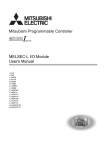
1
L Series Programmable Logic Controllers
PERFORMANCE
Programmable Logic Controllers
L Series
series
E XPA N DA B I L I T Y
L Series CPU Modules......................................................................................................................133
Power Supplies.................................................................................................................................135
Digital I/O Expansion........................................................................................................................135
Connectors, Cables and Terminal Blocks..........................................................................................138
Analog I/O Modules..........................................................................................................................138
A/D Converter Module......................................................................................................................139
Intelligent Function Modules............................................................................................................141
Networks..........................................................................................................................................146
Accessories......................................................................................................................................148
Stock Product: Stock product is product MEAU makes every effort to have on hand for immediate shipment. There may be instances
when we are out of stock due to unexpected large requirements. All stock product will be indicated in this book by an “S” in the Stocked
Item columns/rows.
Non-Stock Product: Non-stock product is product supplied on an “as-needed” basis. Standard lead times of 12 - 16 weeks apply,
product is non-returnable and non-cancelable. Product listed as non-stock may change to stock product subject to increases in sales
and usage. All non-stock product will be indicated in this book by a dash “-” in the Stocked Item columns/rows.
Mitsubishi Electric Automation
|
Programmable Logic Controllers L Series 131
n PROGRAMMABLE LOGIC CONTROLLERS L SERIES
L Series System Configuration
Display unit
(optional)
SD memory card *1
(optional)
END cover
C E F
Power supply module
RS-232 adapter
(optional)
CPU module
Branch module
I/O modules or
intelligent function
modules
END cover with
ERR terminal
(optional)
Main block
D
D
D
Extension cable
Dedicated cable with connector
(connector/terminal block converter module)
(optional)
Dedicated cable with connector
(relay terminal module)
(optional)
Connector
Extension block 1
D
Relay terminal module
(optional)
Extension module
Branch module
C E F
D
Connector/terminal block converter module
(optional)
Extension cable
To Extension block 2
A. L Series CPU Modules................................................................................................................................... 133
B. Power Supplies.............................................................................................................................................. 135
C. Digital I/O Expansion..................................................................................................................................... 135
D. Connectors, Cables and Terminal Blocks...................................................................................................... 138
E. Analog I/O Modules....................................................................................................................................... 138
F. Intelligent Function Modules.......................................................................................................................... 141
G. Accessories................................................................................................................................................... 148
132
A. L Series CPU Modules
The L Series is a powerful but compact modular controller with many features built-in to the CPU
itself. The rack-free design promotes high system flexibility with minimum form factor. Built-in
Mini-B USB and Ethernet allow for easy communication, along with a built-in SD/SDHC memory slot
for data logging and memory storage, and built-in digital I/O for simple high-speed counting and
positioning functions. The high-performance version CPU also includes a built-in CC-Link interface
for Master/Local Station networking. This highly flexible architecture makes the L Series ideal for
both stand-alone and networked machines.
Key Features:
●● Flexible rack-free modular design
●● All-in-one CPU with built-in Ethernet, and positioning I/O functions
●● Up to 260K Step memory
●● As low as 9.5ns instruction processing
●● 24 points of built-in I/O
●●
●●
●●
●●
Built-in data logging capabilities
Commonly available SD/SDHC memory media
Expansion capabilities for I/O, Analog, Communication,
and Motion/Positioning
Integration into iQ Works and GX Works2 next generation software
CPU Specifications
Model Number
L02CPU(-P)
L06CPU(-P)
L26CPU(-P)
L26CPU-(P)BT
Stocked Item
S
S
S
S
Certification
UL-cUL-CE
UL-cUL-CE
UL-cUL-CE
UL-cUL-CE
LD Instruction
40ns
9.5ns
MOV Instruction
80ns
19ns
20k steps
60k steps
260k steps
Program Memory (Drive 0)
80 kB
240 kB
1040 kB
Standard RAM (Drive 3)
128 kB
768 kB
768 kB
Standard RAM (Drive 4)
512 kB
1024 kB
2048 kB
Program Memory
64 programs
124 programs
252 programs
Standard RAM
4 files (file register file, local device file, sampling trace file, and module error collection file)
Standard ROM
128 files
Processing Speed
Program Capacity
Memory Capacity
Maximum Number
of Files
Memory Card Type
Max. Number
of Intelligent
Function Module
Parameter
Settings
5VDC Internal
Current
Consumption
256 files
256 files
SD/SDHC
Initial Setting
2048
4096
4096
Refresh
1024
2048
2048
With Display Module
1.00A
1.06A
1.06A
1.43A
Without Display Module
0.94A
1.00A
1.00A
1.37A
No
Yes
Max. I/O Device Points
8192 points (X/Y0 to X/Y1FFF)
Max. Physical I/O Points
1024 points
(X/Y0 to X/Y3FF)
4096 points (X/Y0 to X/YFFF)
Built-in CC-Link
No
No
Weight (kg)
0.37
0.47
Dimensions (W x H x D) mm
70 x 90 x 95
98.5 x 90 x 95
CPU Built-In Input Specifications
Standard Input
Number of Input Points
Rated Input Voltage
Rated Input Current
Minimum Input Response Speed
Input Response Time Setting
Number of Input Points
Rated Input Voltage
High-Speed Input
Rated Input Current
Minimum Input Response Speed
Input Response Time Setting
10 points
24VDC (+20%/-15%, ripple ratio within 5%)
4.1mA TYP. (at 24VDC)
100μs
0.1ms/1ms/5ms/10ms/20ms/70ms
6 points
24V input: 24VDC (+20%/-15%, ripple ratio within 5%)
Differential input: EIA Standard RS-422-A differential type line driver level
24V input: 6.0mA TYP. (at 24VDC)
Differential input: EIA Standard RS-422-A differential type line driver level
10μs
0.01ms/0.1ms/0.2ms/0.4ms/0.6ms/1ms
CPU Built-In Output Specifications
Model Number
Output Type
Number of Output Points
Rated Load Voltage
OFF-ON
Response Time
ON-OFF
L02CPU/L06CPU
L26CPU/L26CPU-BT
Sink Transistor
8 points
5 to 24VDC 0.1A
1μs or less (rated load, resistive load)
1μs or less (rated load, resistive load)
Mitsubishi Electric Automation
L02CPU-P/L06CPU-P
Source Transistor
|
L26CPU-P/L26CPU-P
Programmable Logic Controllers L Series 133
n PROGRAMMABLE LOGIC CONTROLLERS L SERIES
CPU Built-In I/O - Positioning Function Specifications
Number of Control Axes
Control Unit
Positioning Control
PTP Control (*1 )
Positioning Control
Speed-Position
Method
Switching Control
PTP Control (*1 )
Positioning Control
Speed-Position
Range
Switching Control
Speed Command
Acceleration/Deceleration System
Selection
Acceleration/Deceleration Time
Starting Time (1-Axis Linear Control)
Command Pulse
Output
External Input
Pulse Output Method
Maximum Output Speed
Maximum Connection Distance from
Drive Unit
Zero Signal
Speed-Position Switching Signal
Near-Point Dog Signal
Upper and Lower Limit Signal
Drive Unit READY Signal
Minimum Input Response Time
External Output
Deviation Counter Clear Signal
OFF-ON
Response Time
ON-OFF
2 axes
Pulse
INC system, ABS system
INC system
-2147483648 to 2147483647 pulse
0 to 2147483647 pulse
0 to 200kpulse/s
Automatic trapezoidal acceleration/deceleration and S-pattern acceleration/deceleration
0 to 32767ms
Trapezoidal acceleration/deceleration (1-axis start): 30μs/axis
S-pattern acceleration/deceleration (1-axis start): 35μs/axis
Open collector output (5 to 24VDC), sink or source logic
200kpulse/s
2m
24VDC 6mA Equivalent with differential driver 20mA
DC24V 4.1mA
Zero signal: 10μs Speed-position switching signal, near-point dog signal: 100μs
Upper and lower limit signal, drive unit READY signal: 2ms
ADY signal: 2ms External output; Deviation counter clear signal, sink or source logic
1μs or less (rated load, resistive load)
Note:
1. The abbreviation for Point To Point, referring to position control.
CPU Built-In I/O - High Speed Counter Specifications
Number of Channels
Phase
Count Input Signal
Counter
Coincidence Output
External Input
External Output
PWM Output
Pulse Width
Measurement
134
Signal Level
24V Input
Differential Input
Maximum Counting Speed
Counting Range
Type
Minimum Count
Phase 1
Pulse Width (Duty
Phase 2
Ratio 50%)
Minimum Phase Differential for
2-Phase Input
Comparison Range
Comparison Result
24V Input
Phase Z (Preset)
Differential Input
Function Start
Latch
Minimum Input Response Time
Comparison Output
Output Voltage/Current
Output Response OFF-ON
Time
ON-OFF
Output Frequency Range
Minimum ON Width
Duty Ratio
Measurement Item
Measurement Resolution
Measurement Points
2ch
1-phase input (multiple of 1/2), CW/CCW, 2-phase input (multiple of 1/2/4)
24VDC 6mA
EIA Standard RS-422-A differential type line driver level
(Equivalent with AM26LS31 (manufactured by Texas Instruments Japan Limited))
200kpulse/s (1-phase multiple of 2, 2-phase multiple of 4)
Binary with 32-bit code (-2147483648 to 2147483647)
UP/DOWN preset counter (+ ring counter function)
5μs
10μs
5μs
Binary with 32-bit code (-2147483648 to 2147483647)
Set value < Count value; Set value = Count value; Set value > Count value
Open collector; 24VDC 6mA
EIA Standard RS-422-A differential type line driver level
(Equivalent with AM26LS31 (manufactured by Texas Instruments Japan Limited))
24VDC 4.1mA
Phase Z: 10μs Function start, latch: 100μs
2 points/ch
5 to 24VDC 0.1A
1μs or less (rated load, resistive load)
DC to 200kHz
1μs
ON time can be set in increments of 0.1μs.
Pulse width (ON width: 200μs or more, OFF width: 200μs or more)
5μs
1 point/ch
CPU Built-In Ethernet Port Specifications
Data Transfer Speed
Communication Mode
Transmission Method
Transmission Maximum Distance Between
Specification Hub and Node
Maximum Number 10BASE-T
of Connectable
100BASE-TX
Nodes
TCP/IP
Number of
Connections UDP/IP
Cable to Use For 10BASE-T Connection
(*2)
For 100BASE-TX Connection
100/10Mbps
Full-duplex/Half-duplex
Base band
100m
Maximum of cascading hub connections
Maximum of 2 cascading hub connections
Total of 16 for socket communications, MELSOFT connections, and MC protocol (*1). One for FTP
Cables compliant to Ethernet standards, category 3 or higher (STP/UTP cables) (*3)
Cables compliant to Ethernet standards, category 5 or higher (STP cables)
Notes:
1. Only 3E frames may be used.
2. Straight through cable. Also, CPU is connected directly with a GOT, a cross cable may be used.
3. The use of STP (Shielded Twisted Pair) cables is recommended in noisy environments.
B. Power Supplies
The L Series has three Power Supply Units selectable according to AC/DC power requirements.
Power Supply Module Specifications
Model Number
L61P (*1)
L63P
L63SP
Stocked Item
S
S
S
Certification
UL • cUL • CE
Input Power Supply
100 to 240 VAC (-15% to +10%)
24 VDC (-35% to +30%)
24 VDC (-35% to +30%)
AC Supply Frequency
50/60Hz (-5% to +5%)
-
-
AC Supply Voltage Distortion Factor
Within 5%
-
-
Maximum Input Apparent Power
130 VA
-
-
Maximum Input Power
-
45W
45W
Inrush Current
≤8ms @ 20A
≤1ms @ 100A (for 24 VDC input)
100A within 1ms (24 VDC input)
Rated Output Current (5VDC)
5A
Allowable Momentary Power Failure Time
10ms
10ms (24 DC input)
Within 10ms (24 VDC input)
Weight (kg)
0.32
0.29
0.19
Dimensions (W x H x D) mm
45 x 90 x 95
29 x 90 x 95
Note:
1. AC Power Supply included in CPU sets; L02CPU-SET, L06CPU-SET, L26CPU-SET, and L26CPU-BT-SET
C. Digital I/O Expansion
Aside from the built-in I/O, the L Series has several I/O expansion options for Relay and
Transistor.
Digital Input Module Specifications (AC / DC Input Module)
Model Number
Stocked Item
Certification
Number of Input Points
Rated Input Voltage
Rated Input Current
Response Time
OFF-ON
ON-OFF
Common Terminal Arrangement
LX10
S
UL • cUL • CE
16 points
100 to 120VAC (+10%/
-15%), 50/60Hz (±3Hz)
LX28
S
8 points
100 to 240VAC (+10%/
-15%), 50/60Hz (±3Hz)
16.4mA (200VAC, 60Hz),
8.2mA (100VAC, 60Hz),
13.7mA (200VAC, 50Hz)
6.8mA (100VAC, 50Hz)
8.2mA (100VAC, 60Hz),
6.8mA (100VAC, 50Hz)
15ms or less (100VAC
15ms or less (100VAC
50Hz, 60Hz)10ms or less
50Hz, 60Hz)
(200VAC 50Hz, 60Hz)
20ms or less (100VAC
20ms or less (100/200VAC
50Hz, 60Hz)
50Hz, 60Hz)
16 points/common
8 points/common
(common terminal: TB17) (common terminal: TB17)
LX40C6
S
LX41C4
S
LX42C4
S
16 points
32 points
64 points
24VDC (+20/-15%, ripple ratio within 5%)
6.0mA TYP.
(at 24VDC input)
4.0mA TYP.
(at 24VDC input)
1ms/5ms/10ms/20ms/70ms (Initial setting is 10ms.)
16 points, 1 common
32 points, 1 common
Weight (kg)
16 points (I/O assignment: 32 points (I/O assignment:
16 input points)
32 input points)
18-point screw terminal block (M3 × 6 screw)
18-point terminal block
40-pin connector
100mA
90mA (TYP. all points ON) 80mA (TYP. all points ON) 90mA (TYP. all points ON)
(TYP. all points ON)
0.17
0.15
0.15
0.11
Dimensions (W x H x D) mm
28.5 x 90 x 117
Number of Occupied I/O Points
External Connections
5VDC Internal Current Consumption
4.0mA TYP.
(at 24VDC input)
16 points (I/O assignment: input 16 points)
32 points, 1 common
64 points (I/O assignment:
64 input point)
40-pin connector x 2
120mA
(TYP. all points ON)
0.12
28.5 x 90 x 95
Mitsubishi Electric Automation
|
Programmable Logic Controllers L Series 135
n PROGRAMMABLE LOGIC CONTROLLERS L SERIES
Digital Output Module Specifications
Model Number
Stocked Item
Certification
Number of Output Points
Maximum Load Voltage
Maximum Load Current
LY10R2 (Relay)
S
UL • cUL • CE
16 points
24VDC / 240VAC
2A/point, 8A/common
16 points/common
16 points (I/O assignment: 16 input points)
18-point terminal block
460mA (TYP. all points ON)
0.21
28.5 x 90 x 117
Surge Suppressor
Fuse
Common Terminal Arrangement
Number of Occupied I/O points
External Connections
5VDC Internal Current Consumption
Weight (kg)
Dimensions (W x H x D) mm
Protection Function
LY20S6 (Triac)
S
264VAC
0.6A/point, 4.8A/common
CR absorber
16 points/common (common terminal: TB17)
16 points (I/O assignment: output 16 points)
18-point screw terminal block (M3 × 6 screw)
300mA (TYP. all points ON)
0.22
Digital Output Module Specifications (Sink Transistor Output Modules)
Model Number
LY40NT5P
LY41NT1P
LY42NT1P
Stocked Item
S
S
S
Certification
UL • cUL • CE
Number of Output Points
16 points
32 points
64 points
Rated Load Voltage
12 to 24VDC (+20%/-15%)
Maximum Load Current
OFF-ON
Response Time
ON-OFF
Voltage
External Supply Power
Current
Common Terminal Arrangement
0.5A/point, 5A common
0.1A / point, 2A / common
0.5ms or less
1ms or less (rated load, resistive load)
12 to 24VDC (+20%/-15%, ripple ratio within 5%)
9mA (at 24VDC)
13mA (at 24VDC)/common
16 points/common
32 points/common
Number of Occupied I/O points
16 points (I/O assignment: 16 output points) 32 points (I/O assignment: 32 output points) 64 points (I/O assignment: 64 output points)
External Connections
18-point terminal block
40-pin connector
40-pin connector x 2
5VDC Internal Current Consumption
100mA (TYP. all points ON)
140mA (TYP. all points ON)
190mA (TYP. all points ON)
Weight (kg)
0.15
0.11
0.12
Dimensions (W x H x D) mm
28.5 x 90 x 117
136
9mA (at 24VDC)/common
32 points/common
Digital Output Module Specifications (Source Transistor Output Modules)
Model Number
Stocked Item
Certification
Number of Output Points
Rated Load Voltage
Maximum Load Current
OFF-ON
Response Time
ON-OFF
Voltage
External Supply Power
Current
Common Terminal Arrangement
Number of Occupied I/O points
External Connections
5VDC Internal Current Consumption
Weight (kg)
Dimensions (W x H x D) mm
LY40PT5P
S
UL • cUL • CE
16 points
10.2 to 28.8VDC
0.5A / point, 5A / common
0.5ms or less
1ms or less (rated load, resistive load)
10.2 to 28.8VDC (ripple ratio within 5%)
17mA (at 24VDC)
16 points/common
16 points
(I/O assignment: 16 output points)
18-point screw terminal block
100mA (TYP. all points ON)
0.15
28.5 x 90 x 117
LY41PT1P
S
LY42PT1P
S
32 points
64 points
0.1A / point, 2A / common
20mA (at 24VDC)
32 points/common
32 points (
I/O assignment: 32 output points)
40-pin connector
140mA (TYP. all points ON)
0.11
20mA (at 24VDC)/common
32 points/common
64 points
(I/O assignment: 64 output points)
40-pin connector
190mA (TYP. all points ON)
0.12
Combination I/O Modules
Model Number
Stocked Item
Certification
Number of Input Points
Rated Input Voltage
Rated Input Current
Number of Output Points
Output Type
Rated Load Voltage
Maximum Load Current
OFF-ON
ON-OFF
OFF-ON
Output Response Time
OFF-ON
Voltage
External Supply Power
Current
Input Common Terminal Arrangement
Output Common Terminal Arrangement
Number of Occupied I/O points
External Connections
5VDC Internal Current Consumption
Weight (kg)
Dimensions (W x H x D) mm
Input Response Time
LH42C4NT1P
S
UL • cUL • CE
32 points
24 VDC (ripple rate 5% or less)
4.0mA TYP (at 24 VDC)
32 points
Sink
10.2 to 28.8 VDC
0.1A/point, 2A / commom
1ms, 5ms, 10ms, 20ms, 70ms, or less
1ms, 5ms, 10ms, 20ms, 70ms, or less
0.5ms or less
1ms or less
12/24 VDC (ripple rate: 5% or less)
9mA (at 24 VDC)/common
32 points / common
32 points / common
32 points
40-pin connector
160 mA (TYP all points ON)
0.12
28.5 x 90 x 95
LH42C4PT1P
S
L6EXB
S
UL • cUL • CE
0.08
0.12
28.5 x 90 x 95
L6EXE
S
Source
20mA (at 24 VDC) / common
150mA (TYP all points ON)
0.12
Branch and Extension Modules
Model Number
Stocked Item
Certification
5VDC Internal Current Consumption
Weight (kg)
Dimensions (W x H x D) mm
0.08
0.13
Mitsubishi Electric Automation
|
Programmable Logic Controllers L Series 137
n PROGRAMMABLE LOGIC CONTROLLERS L SERIES
D. Connectors, Cables and Terminal Blocks
For connector type I/O, all L Series and Q Series modules use the same FCN connector. Connectors, cables and terminal blocks are available for both.
Category
Connectors (For User-Made Cables)
Direct-Wire Cables
Terminal Block Dedicated Cables
Terminal Blocks
Extension Cable
Model Number
Description
Stocked Item
A6CON1
FCN, 40 Pin, Solder Type
S
Applicable Products (*1)
A6CON2
FCN, 40 Pin, Crimp Type
S
A6CON3
FCN, 40 Pin, IDC Type
S
A6CON4
FCN, 40 Pin, Solder Type, LowProfile
-
LCBL40P-2M
2.0m I/O Pigtail Cable, 40 Pin
S
LCBL40P-5M
5.0m I/O Pigtail Cable, 40 Pin
S
LCBL40P-10M
10m I/O Pigtail Cable, 40 Pin
S
FA-SCBL05FMV-M
0.5m Terminal Block Cable
S
FA-SCBL10FMV-M
1.0m Terminal Block Cable
S
FA-SCBL15FMV-M
1.5m Terminal Block Cable
-
FA-SCBL20FMV-M
2.0m Terminal Block Cable
S
AC_TB
Terminal Block Cable. _ = 0.5m,
1.0m, 2.0m, 3.0m, 4.0m, 5.0m,
8.0m, 10.0m length
S
A6TBXY36, A6TBXY54
FA-LTB40P
Terminal Block, 40 Point
S
L02CPU, L26CPU-BT
A6TBXY36
Terminal Block, 32 Point
S
A6TBXY54
Terminal Block, 32 Point, 2-Wire
-
LY41NT1P, LY42NT1P, LY41PT1P,
LY42PT1P, QX41_, QX42_, QY41_,
QY42_, QH_, QX41Y41P
LC06E
0.6m Extension Cable
S
L6EXB
LC10E
1.0m Extension Cable
S
LC30E
3.0m Extension Cable
S
L02CPU, L26CPU-BT, LX_, LY_,
LD75_, LD62_, QX_, QY_, QH42P,
QX41Y41P, Q66DA-G, Q68RD3-G,
QD75_, QD72P3C3
L02CPU, L26CPU-BT, LX_, LY_,
LD75_, LD62_, QX_, QY_, QH42P,
QX41Y41P, Q66DA-G, Q68RD3-G,
QD75_, QD72P3C3
FA-LTB40P
L6EXE
Note:
1. Applicable products are FCN connector type CPUs and Modules.
E. Analog I/O Modules
Analog input and output modules can be added on and configured easily in GX Works2 using built-in utilities.
Model Number
Stocked Item
Certification
Number of Analog I/O Points
Voltage
Analog I/O
Current
Output
Digital Output
When Using Scaling
Function
L60AD4 (Analog Input Module)
S
UL • cUL • CE
4 points (ch)
-10 to 10VDC (Input resistance value 1MΩ)
0 to 20mADC (Input resistance value 250Ω)
-20480 to 20479
Voltage
I/O Characteristics, Resolution
Current
Ambient Temperature
25 ±5°C
Ambient Temperature
0 to 55°C
Conversion Speed
Absolute Maximum Input
Output Short Protection
External Power Supply
I/O Device Points Occupied
External Connections
5VDC Internal Current Consumption
Weight (kg)
Dimensions (W x H x D) mm
-10 to 10VDC (External load resistance value 1kΩ to 1MΩ)
0 to 20mADC (External load resistance value 0Ω to 600Ω)
-32768 to 32767
Analog Input Range
Accuracy
L60DA4 (Analog Output Module)
S
0 to 10V
0 to 5V
1 to 5V
-10 to 10V
Users range
setting
0 to 20mA
4 to 20mA
Users range
setting
Digital Output
Resolution
Value
500μV
0 to 20000
250μV
200μV
500μV
-20000 to
20000
307μV (*1)
0 to 20000
1000nA
800nA
-20000 to
20000
1230nA (*1)
Analog Output Range
0 to 5V
1 to 5V
Voltage -10 to 10V
Users range
setting
0 to 20mA
4 to 20mA
Current
Users range
setting
0 to 20000
-20000 to
20000
Resolution
250μV
200μV
500μV
333μV (*1)
0 to 20000
1000nA
800nA
-20000 to
20000
700nA (*1)
±0.1% (±20 digit)
±0.1% (voltage: ±10mA, current: ±20μA)
±0.2% (±40 digit)
±0.3% (voltage: ±30mV, current: ±60μA)
High speed: 20μs/ch; Medium speed: 80μs/ch; Low speed: 1ms/ch 20μs/ch
Voltage: ±15V, Current: 30mA (*2)
Available
24VDC (+20%/-15%); Ripple, spike within 500mVp-p
Inrush current: 4.3A, 1000μs or less; Current consumption: 0.18A
16 points (I/O assignment: 16 points for Intelligent function module)
18-point terminal block
0.52A
0.16A
0.19
0.20
28.5 x 90 x 117
Notes:
1. Maximum resolution in users range settings.
2. Maximum instantaneous current value that will not cause destruction of the internal components. The maximum constant input current value is 24mA.
138
Digital Value
A/D Converter Module
Model Number
Stocked Item
Certification
Number of Analog I/O Points
Voltage
Analog I/O
Current
Output
Digital Output
When Using Scaling
Function
I/O Characteristics, Resolution (*1)
Reference Accuracy
Accuracy (Accuracy
(*4)
for the Maximum
Value of the Digital
Temperature
Output Value) (*3)
Coefficient (*5)
Conversion Speed
Absolute Maximum Input
Offset/Gain Setting Count (*7)
Insulation Method
Dielectric Withstand Voltage
Insulation Resistance
Number of Occupied I/O Points
Connected Terminal
Applicable Wire Size
Applicable Solderless Terminal
5VDC Internal Current Consumption
Weight (kg)
Dimensions (W x H x D) mm
L60AD4-2GH
S
UL • cUL • CE
4 points (4 channels)
-10 to 10VDC (Input resistance value 1MΩ)
0 to 20mADC (Input resistance value 250Ω)
-32000 to 32000
-32768 to 32767
Analog Input Range
0 to 10V
0 to 5V
1 to 5V
Voltage -10 to 10V
1 to 5V (Extended mode)
User range setting
(bi-polar: voltage)
0 to 20mA
4 to 20mA
Current
4 to 20mA (Extended mode)
User range setting
(uni-polar: current)
Digital Output Value
-32000 to 32000
-8000 to 32000
Maximum Resolution
312.5μV
156μV
125μV
312.5μV
125μV
-32000 to 32000
200μV (*2)
0 to 32000
-8000 to 32000
625nA
500nA
500nA
0 to 32000
400nA (*2)
0 to 32000
Within ±0.05% (±16 digit)
±40.1ppm/°C or lower
40μ/2 channels
Voltage: ±15V, Current: 30mA (*6)
Up to 100000 counts
Between I/O terminals and programmable controller power supply: photocoupler isolation;
Between analog input channels: dual channel transformer insulation
Between I/O terminals and programmable controller power supply: 500VAC for 1 minute;
Between analog input channels: 1000VAC for 1 minute
Between I/O terminals and programmable controller power supply: 500VDC 10MΩ or higher
16 points (I/O assignment: 16 points for intelligent)
18-point terminal block
0.3 to 0.75mm²
R1.25-3 (solderless terminals with sleeve are not usable)
0.76A
0.20
28.5 x 90 x 117
Notes:
1. For details on the I/O conversion characteristic, refer the I/O Conversion Characteristic of A/D Conversion in Users Manual.
2. Maximum resolution in the user range setting.
3. Except when receiving noise influence.
4. Accuracy under the ambient temperature when the offset/gain setting is performed.
5. Accuracy when the temperature changes 1°C EX: Accuracy when the temperature changes from 25°C to 30°C 0.05% + 0.00401%/°C (temperature coefficient) × 5°C (temperature change) = 0.070%
6. A momentary input current value which does not cause damage to internal resistors of the module. The maximum input current value for constant application is 24mA.
7. If the number of offset/gain settings exceeds 100000 times, an error occurs. The error code (170) is stored in Latest error code (Un\G19), Error flag (XF) turns on, then the ERR. LED turns on.
Mitsubishi Electric Automation
|
Programmable Logic Controllers L Series 139
n PROGRAMMABLE LOGIC CONTROLLERS L SERIES
Combination Analog Module
Model Number
Stocked Item
Certification
Number of Analog Output Points
Number of Analog Input Points
Input
Digital Input
With Scaling Function
Voltage
Analog Output
Current
Voltage
Analog Input
Current
Output
DIgital Output
With Scaling Function
I/O Characteristics, Resolution (*1)
L60AD2DA2
S
UL • cUL • CE
2 points (2 channels)
2 points (2 channels)
-16384 to 16383
-32768 to 32767
-10 to 10VDC (external load resistance 1kΩ to 1MΩ)
0 to 20mADC (External load resistance 0Ω to 600Ω)
-10 to 10 VDC (input resistance 1MΩ)
0 to 20mADC (input resistance 250Ω)
-16384 to 16383
-32768 to 32767
Analog Output Range
0 to 5V
1 to 5V
Voltage -10 to 10V
User Range Setting
(Bi-Polar: Voltage)
0 to 20mA
Current
4 to 20mA
User Range Setting
Digital Input Value
Analog Input Range
0 to 10V
0 to 5V
1 to 5V
Voltage
-10 to 10V
1 to 5V (Extended mode)
User Range Setting (Voltage)
0 to 20mA
4 to 20mA
Current
4 to 20mA (Extended mode)
User Range Setting (Current)
Digital Output Value
0 to 16000
Analog Output Range
Voltage
Current
Accuracy (Accuracy for the Maximum Value of
the Analog Output Value) (*3)
Analog Input Range
Voltage
Current
Conversion Speed
Output Short Protection
Offset/Gain Setting Count (Flash Memory
Write Count) (*5)
Insulation Method
Dielectric Withstand Voltage
Insulation Resistance
Number of Occupied I/O Points
Connected Terminal
Applicable Wire Size
Applicable Solderless Terminal
External Power Supply
Internal Current Consumption (5VDC)
Weight (kg)
Dimensions (W x H x D) mm
0 to 5V
1 to 5V
-10 to 10V
0 to 20mA
4 to 20mA
0 to 10V
-10 to 10V
0 to 5V
1 to 5V
1 to 5V (Extended mode)
0 to 20mA
4 to 20mA
4 to 20 mA (Extended mode)
-16000 to 16000
Resolution
416μV
333μV
625μV
-12000 to 12000
319μV (*2)
0 to 12000
0 to 12000
-12000 to 12000
-3000 to 13500
-12000 to 12000
Resolution
625µV
416µV
333µV
625µV
333µV
321µV
1666nA
1333nA
1333nA
1287nA (*2)
Ambient Temperature
25 ±5°
0 to 55°
Within ±0.2% (±10mV)
Within ±0.4% (±20mV)
Within ±0.2% (±20mV)
Within ±0.4% (±40mV)
Within ±0.2% (±40µA)
Within ±0.4% (±80µA)
0 to 12000
-16000 to 16000
-3000 to 13500
-1200 to 12000
0 to 12000
Ambient Temperature
25±5º C
0~55º C
±0.2% (±32 digit)
± 0.3% (±48 digit)
± 0.2% (± 24 digit)
± 0.3% (± 36 digit)
80μ/channel (*4)
Protected
Up to 100000 counts
Between I/O terminals and programmable controller power supply: photocoupler isolation; Between I/O channels: no isolation
Between the external power supply and analog I/O channels: transformer isolation
Between I/O terminals and programmable controller power supply: 500VAC for 1 minute;
Between the external pwer supply and analog I/O: 500VAC for 1 minute
Between I/O terminals and programmable controller power supply: 500VDC 10MΩ or higher
16 points (I/O assignment: 16 points for intelligent)
18-point terminal block
0.3 to 0.75mm²
R1.25-3 (solderless terminals with sleeve are not usable)
24VDC +20%, -15%; Ripple, spike 500mVp-p or lower; Inrush current 3.5A, 1000µ or shorter; Current consumption 0.12A
0.17A
0.22
28.5 x 90 x 117
Notes:
1. For details on the I/O conversion characteristic, refer to the I/O Conversion Characteristic of A/D Conversion in Users Manual.
2. Maximum resolution in the user range setting.
3. Except when receiving noise influence.
4. For details on the conversion speed, refer to the enable/disable settings and conversion speed of A/D and D/A in the Users Manual.
5. If the number of offset/gain settings exceeds 100000 times, an error (error code 170) occurs.
140
166nA
1333nA
696nA (*2)
F. Intelligent Function Modules
Temperature I/O Modules
Model Number
L60TCTT4
L60TCRT4
L60TCTT4BW
L60TCRT4BW
Stocked Item
S
S
S
S
Control Output
Transistor output
Number of Temperature Input Points
4 channels/module
Type of Usable Temperature Sensors, the Temperature
Measurement Range, the Resolution, and the Effect From
Wiring Resistance of 1Ω
Thermocouple
Resistive thermal device
Thermocouple
Resistive thermal device
Indication
Accuracy
Accuracy
Cold Junction
Temperature
Compensation
Accuracy:
(Ambient
Temperature:
0 to 55°C)
Ambient Temperature:
25 ±5°C
Full scale × (±0.3%)
Ambient Temperature:
0 to 55°C
Full scale × (±0.7%)
Temperature Process
Value (PV): -100° C or
More
Within ±1.0°C
Temperature Process
Value (PV): -150 to
-100°C
Within ±2.0°C
Temperature Process
Value (PV): -200 to
-150°C
Within ±3.0°C
Within ±1.0°C
-
250ms/4 channels, 500ms/4 channels
Control Output Cycle
0.5 to 100.0s
Input Impedance
1MΩ
Input Filter
0 to 100s (0: Input filter OFF)
Sensor Correction Value Setting
-50.00 to 50.00%
Operation at Sensor Input Disconnection
Upscale processing
Temperature Control Method
PID ON/OFF pulse or two-position control
PID Constants Setting
Can be set by auto tuning
Proportional Band (P)
0.0 to 1000.0% (0: Two-position control)
Integral Time (I)
0 to 3600s (set 0 for P control and PD control)
Derivative Time (D)
0 to 3600s (set 0 for P control and PI control)
Set Value (SV) Setting Range
Within the temperature range set in the thermocouple/platinum resistance thermometer to be used
Dead Band Setting Range
Transistor Output
0.1 to 10.0%
Output Signal
ON/OFF pulse
Rated Load Voltage
10 to 30VDC
Max. Load Current
0.1A/point, 0.4A/common
Max. Inrush Current
0.4A 10ms
Leakage Current at OFF
0.1mA or less
Max. Voltage Drop at ON
1.0VDC (TYP) at 0.1A 2.5VDC (MAX) at 0.1A
Response Time
OFF–ON: 2ms or less, ON–OFF: 2ms or less
Number of Accesses to Non-Volatile Memory
Heater Disconnection Detection
Specifications
-
Within ±3.0°C
Sampling Cycle
PID Constants Range
Within ±2.0°C
Max. 1012 times
Current Sensor
Input Accuracy
See L Series User’s Manual
-
Full scale × (±1.0%)
Number of Alert Delay
3 to 255
Number of Occupied I/O Points
16 points (I/O assignment: 16 intelligent points)
Number of Occupied Module
1
External Connection
18-point terminal block
Internal Current Consumption
0.30A
Weight (kg)
0.18
0.33
Dimensions (W x H x D) mm
28.5 x 90 x 117
57.0 x 9 x 117
2
Two 18-point terminal blocks
0.31A
Mitsubishi Electric Automation
0.33A
|
0.35A
Programmable Logic Controllers L Series 141
n PROGRAMMABLE LOGIC CONTROLLERS L SERIES
LD77MH4
RUN
ERR.
P
U
L
S
E
R
AX
LD77MH16
RUN AX 1 2 3 4 5 6 7 8
1
2
3
4
9 10 11 121314 1516
ERR.
CN1
P
U
L
S
E
R
CN1
Simple Motion Modules
Model Number
LD77MH4
LD77MH16
Stocked Item
S
S
Number of Control Axes
4
16
Operation Cycle (ms)
0.88
0.88/1.77
Control System
PTP (Point To Point) control, path control (both linear and arc can be set), speed control, speed-position switching
control, position-speed switching control, Speed-torque control
Control Unit
mm, inch, degree, PLS
Positioning Data
600 data/axis. (Can be set with GX Works2 or sequence program)
Backup
Parameters, positioning data, and block start data can be saved on flash ROM (battery-less backup)
Positioning System
PTP control: Incremental system/absolute system; Speed-position switching control: Incremental system/absolute
system (*1); Position-speed switching control: Incremental system; Path control: Incremental system/absolute system
Applicable Connector for External Input Signal
SSCNET III Cable
LD77MHIOCON
MR-J3BUS_M [m (ft)] (*2)
LD77MH MR-J3(W)-_B/MR-J3(W)-_B MR-J3(W)-_B; Standard cord for inside panel; 0.15 (0.49), 0.3 (0.98),
0.5 (1.64), 1 (3.28), 3 (9.84)
MR-J3BUS_M-A [m (ft)] (*2)
LD77MH MR-J3(W)-_B/MR-J3(W)-_ MR-J3(W)-_B; Standard cable for outside panel; 5 (16.40), 10 (32.81),
20 (65.62)
MR-J3BUS_M-B [m (ft)] (*2,*3)
LD77MH MR-J3(W)-_B/MR-J3(W)-_B MR-J3(W)-_B; Long distance cable; 30 (98.43 ), 40 (131.23), 50 (164.04)
5VDC Internal Current Consumption (A)
0.55
Flash ROM Write Count
Max. 100000 times
Number of Occupied I/O Points (Points)
32 (I/O assignment: Intelligent function module 32 points)
Number of Applicable Modules
Up to 5 modules
Outline Dimensions mm (inch) W x H x D
45.0 x 90.0 x 95.0 (1.77 x 3.54 x 3.74)
Weight (kg)
0.22
External Command Signal - Switching Signal
DI signal (External start or speed-position switching can be selected by parameter.)
0.70
Notes:
1. In speed-position switching control (ABS mode), the control unit available is “degree” only.
2. _ = Cable length: (015: 0.15m (0.49ft.), 03: 0.3m (0.98ft.), 05: 0.5m (1.64ft.), 1: 1m (3.28ft.), 3: 3m (9.84ft.), 5: 5m (16.40ft.), 10: 10m (32.81ft.), 20: 20m (65.62ft.), 30: 30m (98.43ft.), 40: 40m (131.23ft.),
50: 50m (164.04ft.) )
3. For the cable of less than 30[m](98.43[ft.]), contact your nearest Mitsubishi sales representative.
142
SSCNET III Head Module
Model Number
Stocked Item
Certification
Maximum Link Points Per RWr, RX
Network
RWw, RY
Maximum Link Points Per RWr, RX
Station
RWw, RY
Communication Speed
Maximum Connectable
Communication
Stations Per Network (*1) Cycle:
Connection Cable
Maximum Station-to-Station Distance
Connection Method
Transmission System
Encoding Method
Transmission Format
Synchronization Method
Communication Cycle
Error Control System
Head Module
X
Number of I/O Points (*2)
Y
X
Y
SB
SW
Number of Device Points
SM
SD
W
Uoo\Goo
Number of Writes to the Parameter Memory
Clock Function (For Displaying the Date and
Time of an Error)
Allowable Momentary Power Failure Time
Internal Current Consumption (5VDC) A
Laser Classification (JIS C 6802, IEC 60825-1)
Weight (kg)
Dimensions (W x H x D) mm
LJ72MS15
S
UL • cUL • CE
256 bytes in total
256 bytes in total
64 bytes in total
64 bytes in total
150Mbps
888μs: 4 stations
444μs: 2 stations
222μs: 1 station
SSCNET III cable (optical fiber cable)
POF type: 20m; H-PCF type: 50m
Daisy chain connection (Regenerative relay system with a servo amplifier)
Full-duplex communication (because of the separation of the channels for sending and receiving)
8B10B + scramble
Original to SSCNET III/H
Synchronization of the control cycle and communication cycle that synchronize with the data transmission of the Motion controller
222μs/444μs/888μs
CRC
4096 points, 512 bytes (Number of points accessible to the actual module)
4096 points, 512 bytes (Number of points accessible to the actual module)
8192 points, 1KB (Number of usable points on programs); (RX0 is assigned from X0)
8192 points, 1KB (Number of usable points on programs); (RY0 is assigned from Y0)
8192 points, 1KB
8192 points, 16KB
2048 points, 256 bytes
2048 points, 4KB
8192 points, 16KB; (RWw0 is assigned from W0, RWr0 is assigned from W1000)
Devices that directly access the buffer memory of intelligent function modules
Up to 100000 times
Year, month, date, hour, minute, and second (automatic leap year detection) When connected to a network, the clock synchronizes
periodically with the clock in the Motion controller via the network. (Initial value: 2000/1/1 00:00:00) After the clock information has
been acquired from the Motion controller, when the head module is powered off then on, the clock resumes from the time when the
power was last turned off. (The clock pauses during power off.) Therefore, the data and time of an error that occurred during initial
processing may be different from the actual one.
Depends on the power supply module used
0.55
Class 1
0.20
50 x 90 x 95
Notes:
1. This number includes only head modules. Servo amplifiers are not included.
2. This is the maximum number of points that can be assigned to the actual module in “PLC Parameter” - “I/O Assignment” of GX Works2.
Mitsubishi Electric Automation
|
Programmable Logic Controllers L Series 143
n PROGRAMMABLE LOGIC CONTROLLERS L SERIES
Positioning Modules
Open collector and differential line driver pulse positioning modules can be added on and configured in
GX Works2 using built-in utilities.
Model Number
Stocked Item
Certification
Number of Control Axes
LD75P1/LD75D1 (*1)
S
UL • cUL • CE
1 axis
Interpolation Function
None
Control System
Control Unit
Positioning Data
Backup
PTP Control (*1)
Speed-Position
Positioning Switching Control
Control
Position-Speed
System
Switching Control
Path Control
In Absolute System
In Incremental
System
Positioning
Control
Positioning
Control
In speed-Position
Range
Switching Control
(INC Mode)/PositionSpeed Switching
Control
In Speed-Position
Switching Control
(ABS Mode) (*2)
Speed Command
Acceleration/Deceleration System
Selection
Acceleration/Deceleration Time
Sudden Stop Deceleration Time
Starting Time (*3)
External Wiring Connection System
Applicable Wire Size
Applicable Connector For External Device
Max. Output Pulse
Max. Connection Distance Between Servos
Internal Current Consumption (5VDC)
Flash ROM Write Count
No. of Occupied I/O Points
Weight (kg)
Dimensions (W x D x H) mm
LD75P2/LD75D2 (*1)
S
LD75P4/LD75D4 (*1)
S
2 axes
4 axes
2-axis linear interpolation
2-, 3-, or 4-axis linear interpolation
2-axis circular interpolation
2-axis circular interpolation
PTP (Point To Point) control, path control (both linear and arc can be set), speed control, speed position switching control,
position-speed switching control
mm, inch, degree, pulse
600 data/axis (Can be set with GX Works2 or program.)
Parameters, positioning data, and block start data can be saved on flash ROM (battery-less backup)
Incremental system/absolute system
Incremental system/absolute system (*2)
Incremental system
Incremental system/absolute system
–214748364.8 to 214748364.7 (μm)
–21474.83648 to 21474.83647 (inch)
0 to 359.99999 (degree)
–2147483648 to 2147483647 (pulse)
–214748364.8 to 214748364.7 (μm)
–21474.83648 to 21474.83647 (inch)
–21474.83648 to 21474.83647 (degree)
–2147483648 to 2147483647 (pulse)
0 to 214748364.7 (μm)
0 to 21474.83647 (inch)
0 to 21474.83647 (degree)
0 to 2147483647 (pulse)
0 to 359.99999 (degree)
0.01 to 20000000.00 (mm/min)
0.001 to 2000000.000 (inch/min)
0.001 to 2000000.000 (degree/min)
1 to 4000000 (pulse/s)
Trapezoidal acceleration/deceleration, S-curve acceleration/deceleration
1 to 8388608 (ms) Four patterns can be set for each of acceleration time and deceleration time
1 to 8388608 (ms)
1-axis linear control
1-axis speed control
2-axis linear interpolation control (Composite speed)
2-axis linear interpolation control (Reference axis speed)
2-axis circular interpolation control
2-axis speed control
3-axis linear interpolation control (Composite speed)
3-axis linear interpolation control (Reference axis speed)
3-axis speed control
4-axis linear interpolation control
4-axis speed control
1.5ms
1.5ms
1.5ms
1.5ms
2.0ms
1.5ms
1.7ms
1.7ms
1.7ms
1.8ms
1.8ms
Factors in starting time extension. The following times will be added to the starting time in the described conditions:
• S-curve acceleration/ deceleration is selected: 0.1ms; Other axis is in operation: 0.5ms; During continuous positioning control:
0.3ms; During continuous path control: 0.3ms
40-pin connector
0.3mm² (22AWG) (for A6CON1 or A6CON4), 0.088 to 0.24mm² (28 to 24AWG) (for A6CON2)
A6CON1, A6CON2, A6CON4 (sold separately)
LD75P1, LD75P2, LD75P4: 200kpulse/s; LD75D1, LD75D2, LD75D4: 4Mpulse/s
LD75P1, LD75P2, LD75P4: 2m; LD75D1, LD75D2, LD75D4: 10m
LD75P1: 0.44A; LD75D1: 0.51A
LD75P2: 0.48A; LD75D2: 0.62A
LD75P4: 0.55A; LD75D4: 0.76A
Max. 100000 times
32 points (I/O assignment: intelligent 32 points)
0.18
45.0 x 95.0 x 90.0
Notes:
1. LD75P represents the open collector output system, and LD75D represents the differential driver output system.
2. In speed-position switching control (ABS mode), the control unit available is “degree” only. (For details, refer to Section 9.2.17 “Speedposition switching control (ABS mode)”.
3. Using the “Pre-reading start function”, the virtual start time can be shortened. (For details, refer to Section 12.7.7 “Pre-reading start function”.
144
High Speed Counting Modules
High-speed counter modules can be added on and configured in GX Works2 using built-in utilities.
Model Number
Stocked Item
Certifications
Number of Channels
Counting Speed Switch Setting
Phase
Count Input
Signal
Signal Level
Maximum Counting Speed
Counting Range
Type
Counter
LD62 (DC Input)
LD62D (Differential Input)
S
S
UL • cUL • CE
2ch
10kpulse/s, 100kpulse/s, 200kpulse/s
10kpulse/s, 100kpulse/s, 200kpulse/s, 500kpulse/s
1-phase input (multiple of 1/2), CW/CCW, 2-phase input (multiple of 1/2/4)
EIA Standard RS-422-A differential type line driver level
5/12/24VDC 2 to 5mA
(Equivalent with AM26LS31)
200kpulse/s
500kpulse/s
Binary with 32-bit code (-2147483648 to 2147483647)
UP/DOWN preset counter (+ ring counter function)
Minimum Count Pulse Width
(Duty Ratio 50%)
10kpulse/s
100kpulse/s
200kpulse/s
50μs
5μs
2.5μs
10kpulse/s
100kpulse/s
200kpulse/s
500kpulse/s
50μs
5μs
2.5μs
1μs
Minimum Phase Differential for
2-Phase Input
10kpulse/s
100kpulse/s
200kpulse/s
25μs
2.5μs
1.25μs
10kpulse/s
100kpulse/s
200kpulse/s
500kpulse/s
25μs
2.5μs
1.25μs
0.5μs
Comparison Comparison Range
Output
Comparison Result
Preset
Function Start
External
Input
OFF-ON
Minimum Input
Response Time
ON-OFF
Comparison Output
Output Voltage/Current
External
Output
Output Response OFF-ON
Time
ON-OFF
I/O Device Points Occupied
External Connections
5VDC Internal Current Consumption (A)
Weight (kg)
Dimensions (W x D x H) mm
Binary with 32-bit code (-2147483648 to 2147483647)
Set value < Count value; Set value = Count value; Set value > Count value
5/12/24VDC 2 to 5mA (Differential type line drivers conform5/12/24VDC 2 to 5mA
ing to EIA standard RS-422-A are also applicable.)
Function start: 0.5ms
Function start: 1ms
2 points/channel
12 to 24VDC 0.5A
0.1ms or less (rated load, resistive load)
16 points (I/O assignment: 16 points for intelligent function module)
40-pin connector
0.31
0.36
0.13
28.5 x 90 x 95
Serial Communication Modules
Serial communication modules can be added on and configured in GX Works2 using pre-defined or user-defined protocols.
Model Number
Stocked Item
Certification
ch1
ch2
Line
MC Protocol
Communication
Pre-Defined Protocol
System
Nonprocedural Protocol
Bidirectional Protocol
Synchronization Method
Interface
Transmission Speed
MC Protocol
Access Cycle
Error Detection
Pre-Defined Protocol
Nonprocedural Protocol
Bidirectional Protocol
Parity Check
Sum Check Code
Transmission Control
LJ71C24
S
UL • cUL • CE
RS-232-compliance (D-Sub 9P female)
RS-422/485-compliance (2-piece terminal block)
Full duplex/half duplex
Half duplex
LJ71C24-R2
S
RS-232-compliance (D-Sub 9P female)
RS-232-compliance (D-Sub 9P female)
Full duplex/half duplex
Start-stop synchronization method
50bps/300bps/600bps/1200bps/2400bps/4800bps/9600bps/14.4kbps/ 19.2kbps/28.8kbps/38.4kbps/57.6kbps/115.2kbps/230.4kbps;
Transmission speed 230.4kbps is only available for channel 1. Total transmission speed of two interfaces is available up to 230.4kbps.
Total transmission speed of two interfaces is available up to 115.2kbps when the communication data monitoring function is used.
Processes one request during installed C24 CPU module END processing. (Number of scans that must be processed/number
of link scans depends on the contents of the request.)
Sends or receives data when requested with the dedicated instruction (CPRTCL).
Sends data each time a send request is issued. Can receive at any time.
All protocols and when ODD/EVEN is selected by parameter.
MC protocol/bidirectional protocol selected by parameter. For the pre-defined protocol, whether or not a sum check code is
needed depends on the selected protocol. Nonprocedural protocol selected by user frame.
DTR/DSR (ER/DR) Control
RS/CS Control
CD Signal Control
DC1/DC3 (Xon/Xoff) Control DC2/DC4 Control
RS-232
Enabled
Enabled
Enabled
Enabled
RS-422/485
Disabled
Disabled
Disabled
Disabled
• DTR/DSR signal control and DC code control are selected by the user.
Transmission
RS-232
Distance (Overall
RS-422/485
Distance)
I/O Device Points Occupied
5VDC Internal Current Consumption (A)
Weight (kg)
Dimensions (W x D x H) mm
Maximum 15m (overall distance)
Maximum 1200m (overall distance)
-
32 points (I/O assignment: 32 points for intelligent function module)
0.39
0.26
0.17
0.14
28.5 x 90 x 118
28.5 x 90 x 99
Mitsubishi Electric Automation
|
Programmable Logic Controllers L Series 145
n PROGRAMMABLE LOGIC CONTROLLERS L SERIES
G. Networks
Ethernet Module
LJ71E71-100
Model Number
100BASE-TX
Stocked Item
Certification
Transmission
Specifications
Sending/
Receiving
Data Storage
Memory
10BASE-T
S
UL • cUL • CE
Data Transmission Speed
100Mbps
Interface
RJ45 (AUTO MDI/MDI-X)
Communication Mode
Full-duplex / Half-duplex
Transmission Method
Base band
Maximum Segment Length
100m (length between a hub and a node)
Maximum Number of Cascade
Connections
Cascade connection
(maximum of 2 levels)
Number of Simultaneous Open
Connections
16 connections (Connections usable on a program)
Fixed Buffer
1k word x 16
Random Access Buffer 6k Words
E-Mail
10Mbps
Half-duplex
Cascade connection
(maximum of 4 levels
6k words x 1
Attachment
6k words x 1
Main Text
960k words x 1
Number of Occupied I/O Points
32 points (I/O assignment: Intelligent 32 points)
Internal Current Consumption (5VDC)
0.60A
Weight (kg)
0.18
External Dimensions (W x H x D) mm
28.5 x 95 x 90
CC-Link IE Field Master/Slave
CC-Link IE Field brings 1 Gigabit speed for cyclic, acyclic and transient data transmission to RJ45 and Cat 5e cabling
infrastructure. Create mixtures of line and star topology, and maintain control over up to 120 controller or remote I/O
stations simultaneously on the same network.
Model Number
Stocked Item
Certification
Network Common Memory
Transient Transmission Capacity
Communication Speed
Connection Cable
Maximum Station-toStation Distance
Ethernet
Total Distance
Number of Cascade
Connections
Transmission Path
Number of Connected Master Station
Stations in One
Local Station
Network
Maximum Number of Networks
Communication Method
Number of Occupied I/O Points
Internal Current Consumption (5VDC) (A)
Weight (kg)
Dimensions (W x H x D) mm
LJ71GF11-T2
S
UL • cUL • CE
32k bytes
2048 bytes
1Gbps
An Ethernet cable that meets the 1000BASE-T standard (Category 5e or higher, shielded RJ45)
100m max. (Compliant with ANSI/TIA/EIA-568-B (Category 5e))
Line topology: 12000m (when connected to 1 master station and 120 slave stations)
Star topology: Depends on the system configuration
Up to 20
Star, Line, Mixed Star & Line, and Ring
1 station
120 stations (Local station or Remote I/O) (*1)
239
Token passing method
32 points (I/O assignment: Intelligent 32 points)
0.89
0.27
45 x 90 x 95
Note:
1. For CC-Link IE Field Remote I/O stations, refer to the LJ72GF15-T2 CC-Link IE Field Slave Head station.
CC-Link IE Field Slave Head Station
In place of an L Series CPU, CC-Link IE Field Slave Head Stations can be used to provide remote control over Digital I/O, Analog,
Motion, High-Speed Counter, Serial Communication, and CC-Link Master/Local Station modules via CC-Link IE Field.
Model Number
Stocked Item
Certification
Transmission Speed
Network Topology
Communication Method
Maximum Number of Mountable Modules
Communication Port
RAS Function
Connection Cable
Dimensions (W x H x D) mm
LJ72GF15-T2 (*1)
S
UL • cUL • CE
1Gbps
Star, Line, Mixed Star & Line, and Ring
Deterministic (token passing)
10 (120 when using extension and branch modules)
CC-Link IE field network port x 2, USB port (Mini-B terminal) x 1
Network event logging, unit error logging, testing, monitoring, and error history preservation function
Ethernet cable (category 5 or higher)
50 x 90 x 95
Note:
1. CC-Link IE Field network requires CC-Link IE Field Master module.
146
CC-Link Master/Local Station
Additional CC-Link Master/Local Stations can be added on and configured in GX Works2.
Model Number
Stocked Item
Certification
Transmission Speed
Maximum Overall Cable Distance (Maximum
Transmission Distance)
Maximum Number of Connected Stations
(Master Station)
Number of Occupied Stations (Local Station)
Remote I/O (RX, RY)
Maximum Number
of Link Points Per
Remote Register (RWw)
System (*1)
Remote Register (RWr)
Remote I/O (RX, RY)
Number of Link
Points Per Station
Remote Register (RWw)
(*1)
Remote Register (RWr)
Transmission Path
RAS Function
Connection Cable
I/O Device Points Occupied
5VDC Internal Current Consumption
Weight (kg)
Dimensions (W x H x D) mm
LJ61BT11
S
UL • cUL • CE
156kbps/625kbps/2.5Mbps/5Mbps/10Mbps
1.2 km (without repeater, varies according to the transmission speed.)
64
1 to 4 stations (The number of stations can be switched using the GX Works2 parameter setting.)
2048 points
256 points (master station remote device station/local station/intelligent device station/standby master station)
256 points (remote device station/local station/intelligent device station/standby master station master station)
32 points (local station is 30 points)
4 points (master station remote device station/local station/intelligent device station/standby master station)
4 points (remote device station/local station/intelligent device station/standby master station master station)
Bus (RS-485)
Automatic return function; Slave station cut-off function; Error detection via link special relay/register
CC-Link dedicated cables compatible with Ver.1.10
32 points (I/O assignment: 32 points for intelligent function module)
0.46A
0.15
28.5 x 90 x 118
Note:
1. Indicates the number of link points for Remote net Ver.1 mode.
IO Link Master
Model Number
ME1IOL6-L
Stocked Item
-
Number of Ports
6
Port Configuration
IO-Link Mode
Digital
Input
SIO Mode
Digital
Output
IO-Link, Digital output (SIO mode), Digital input (SIO mode), Disabled
Rated Voltage
24 VDC
Rated Output Current (C/Q)
15 mA
Rated Sensor/Actuator Supply Current (L+)
200 mA
Input Type
Sink
Rated Voltage
24 VDC
Internal Pull-Down Current (C/Q)
5 mA
Input Filter (HW and SW)
200 μs
Rated Voltage
24 VDC
Rated Output Current (C/Q)
200 mA Max. current per port (sum of C and L+): 215 mA
Rated Sensor/Actuator Supply Current (L+)
Output Type
Push-pull
Communication Line (C/Q)
Port Disabled
Sensor/Actuator Supply Line Switched OFF (L+)
Switched OFF
Protection
Functions
Communication Line (C/Q)
Insulation
Method
Between the I/O Terminals and PLC Power Supply
Photocoupler isolation
Between Channels
No isolation
Sensor/Actuator Supply Line (L+)
Over-current, over-load and short-circuit
Dielectric Withstand Voltage
Between I/O terminals and programmable controller power supply:
500 V ACrms for 1 minute
Insulation Resistance
Between I/O terminals and programmable controller power supply:
500 VDC 10 MΩ or more
Number of I/O Occupied Points
32 points (I/O assignment: Intelligent 32 points)
External Wiring Connection System
18-points terminal block
Cable Specification
Cable Type
Unshielded cable
Maximum Length
20 m
Applicable Wire Size
0.3 to 0.75mm²
Overall Loop Resistance
6Ω
Effective Line Capacitance
3 nF
Applicable Solderless Terminals
External Supply Power
R1.25-3 (Solderless terminals with sleeves cannot be used)
Voltage
24 VDC (+20%, -15%); ripple, spike within 500mVP-P In order to keep the specified
IO-Link output voltage levels (L+ line) the external supply voltage must be higher than
22 VDC
Current (A)
The sum current on the L- lines must not exceed 1.7
Inrush Current
8 A within 230 μs
Internal Current Consumption (5 VDC) (A)
0.06
Online Module Change
Not supported
Weight (kg)
0.18
Mitsubishi Electric Automation
|
Programmable Logic Controllers L Series 147
n PROGRAMMABLE LOGIC CONTROLLERS L SERIES
CC-Link/LT Master Module
Model Number
Stocked Item
Certification
Transmission Speed
Network Topology
Communication Method
Number of Connectable Modules
Number of Occupied I/O Points
5VDC Internal Current Consumption
Weight (kg)
Dimensions (W x H x D) mm
LJ61CL12
UL • cUL • CE
156kbps/625kbps/2.5Mbps
T-branch
Deterministic (CRC)
64
16 points (I/O assignment: 1024points for intelligent function module)
0.16A
0.12
28.5 x 90 x 95
H. Accessories
Display Module Specifications
Use the Display Module for on-site maintenance and troubleshooting, directly from the PLC without a computer or software. Monitor
devices, force devices and adjust intelligent function module parameters, all while using User Messages prompted by the program.
Model Number
Stocked Item
Number of Display Characters
Language Selection
Backlight Display
Weight (kg)
Dimensions (W x H x D) mm
L6DSPU (*1)
S
16 characters x 4 lines
English and Japanese
Green and red
0.03
45 x 50 x 17.3
Note:
1. Display unit included in CPU sets, L02CPU-SET and L26CPU-BT-SET.
RS-232 Adapter Specifications
Model Number
Stocked Item
Maximum Data Transmission Speed
5VDC Internal Current Consumption
Weight (kg)
Dimensions (W x H x D) mm
L6ADP-R2
S
115.2kbps
0.02A
0.10
28.5 x 90 x 95
End Cover and End Cover with Error Terminal
Model Number
Stocked Item
Rated Switching Voltage, Current
Minimum Switching Load
L6EC
S
-
Response Time
-
Life
-
Surge Suppressor
Fuse
External Connection System
-
Applicable Wire Size
-
Internal Current Consumption
Weight (kg)
Dimensions (W x H x D) mm
0.04A
0.06
13 x 90 x 95
L6EC-ET
S
24VDC, 0.5A
5VDC, 1mA
OFF to ON: 10ms or less;
ON to OFF: 12ms or less
Mechanical: 20 million or more Electrical: 100
thousand or more for rated switching voltage
and current
None
None
Spring clamp terminal block
0.3 to 2.0mm² (AWG22 to 14)
(Stranded wire/single wire)
0.06A
0.11
28.5 x 90 x 95
Note: L Series CPU modules and the CC-Link IE Field Slave Head Station are supplied with a standard End Cover included.
Backup Batteries
Uses standard Q Series backup batteries. See Programmable Automation Controllers section for more details.
Memory Cards
Mitsubishi provides industrial grade SD memory cards for the L Series. Commercially available SD/SDHC cards
supported up to 32GB.
Model Number
L1MEM-2GBSD
L1MEM-4GBSD
148
Memory Card
2GB
4GB
Stocked Item
S
S