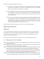
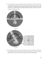
1
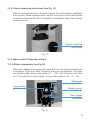
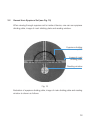
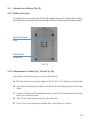
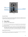
Notification
Dear Users,
Thank you for your purchase of LM 240 Lensmeter. Please take time to read our
user’s manual carefully before use.
This guarantees you to make full use of this unit and prolongs the operation life of
this unit.
Precautions
If you have detected abnormal heat, smoke, noise or smell, immediately stop using
the product.
In the event of an abnormality, turn off the power and disconnect the power plug from
the power socket. Continuing to use the product may result in electric shock or fire.
Observe the instructions given below regarding the power cable:
•
•
•
•
•
•
Be sure to use the supplied or specified power cable.
Do not modify, forcibly bend, kink or pull the power cable.
When disconnecting the power cable from the AC outlet, be sure to hold the cable
by the plug.
Pulling the cable may cause wire breakage or shot circuit, resulting in fire or electric
shock.
Do not connect or disconnect the plug of the power cable to/from the AC outlet
using wet hands.
Doing so may result in electric shock.
Do not touch the product with wet hands while the power cable is connected
to the AC outlet.
Doing so may result in electric shock.
If the product will not be used for a long period, disconnect the power cable
from the power source. Leaving the cable connected to the power socket for
a prolonged period will consume electricity and may result in heating.
Content
1.
Function Introduction .....................................................................................4
2.
Working Principle Device ................................................................................4
3.
Name of Parts ...............................................................................................5
4.
Operation ....................................................................................................16
5.
Maintenance ................................................................................................21
6.
Common Trouble Shooting ...........................................................................23
7.
Specifications ..............................................................................................24
1. Function Introduction
This lensmeter is divided into 2 models, standard model and strengthened model
with prism compensator.
This product is applicable to measurement testing departments, spectacles manufacturers,
retail dealers of spectacles, hospital’s department of ophthalmology and optical element
factories for conducting measurement of spherical lens diopter, cylindrical lens diopter,
cyIindrical lens axis of astigmatism, prism diopter, prism basal angle and cornea contact
lens diopter. In the following description, all chapters or content attached with “*” in
the front are special for strengthened model device with prism compensator.
2. Working Principle Device
Fig. 1 Diagram of Optical Principle of Device
1. Light source
4. Measuring object lens
7. Half 5-edge prism
10.Reading dividing plate
13.Front lens
*16. Prism compensator
2. Color filter piece
5. Diaphragm
8. Eyepiece dividing plate
11. Zero line dividing plate
14. Corner cube prism
3. Mark dividing plate
6. Telescope objective lens
9. Eyepiece set
12. Reflector
15.Rear lens
This device consists of a coaxial optical system. The light emitted from light source
1 (illuminating lamp) passes through color filter piece 2 and lights up mark dividing
plate 3. Then mark dividing plate 3, through measuring object lens 4 and telescope
4
objective 6, and after turning direction through half 5-edge prism 7, is imaged at
eyepiece dividing plate 8. At the same time, the lighted reading dividing plate 10
and zero line dividing plate 11, through front lens 13 and rear lens 15, are also imaged
at eyepiece dividing plate 8. Then, through eyepiece set 9, it is possible for human eyes
to observe clear images of mark dividing plate 3, eyepiece dividing plate 8, reading
dividing plate 10 and zero line dividing plate 11. In operation, place the spectacle lens
at diaphragm 5 (measurement bearing seat). Turn diopter measuring hand-wheel and
astigmatism axis measuring hand-wheel to have a clear image of mark dividing plate 3.
Now, the scale value on the reading dividing plate 10 linked with mark dividing plate 3
is just the diopter reading of the said lens.
3. Name of Parts
First, please take a little time to have a look at picture and illustration on following 11
pages and get familiar with your device.
3.1
Viewed from front side
1. Top cover
2. Eyepiece system
*10. Prism
compensator
6. Printing
mechanism
3. Lens pressing
mechanism
7. Lens pushing
mechanism
4. Measurement
bearing seat
5. Astigmatism axis
measuring,
hand-wheel
8. Diopter
measuring
hand-wheel
9. Mains switch
Fig. 2
5
3.1.1 Top cover (Fig.3)
It is an arch-shape cover plate that can be dismantled, which offers a window
for professional personnel to maintain the device.
Top cover
Fig. 3
Important Matters
For non-professional personnel, please do not open the top cover by yourself, and
do not move internal parts either.
Warning
When moving the device, it is strictly forbidden to hold the top cover so as to avoid
damage to the device (Fig.4) Correct way of moving the device: Support the body
of device with one hand and hold its bottom with other hand.
Fig. 4
6
3.1.2 Eyepiece system (Fig. 5)
The eyepiece system is a screw-type focusing unit with focusing range of + 5D,
which can be adapted to different eyesight of human.
Eyepiece lens
Scale of eyepiece
focusing range
Fig. 5
3.1.3 Lens pressing mechanism (Fig.6)
In this mechanism, 3 plastic pressing feet with spring are used to press lens,
where, lens with any shape of surface can be firmly pressed without damage
to lens surface. In use, lift the lens-pressing handle so that the lens pressing
mechanism is lowered to press the lens. After use, lift the lens-pressing handle
to hang up the lens pressing mechanism.
Lens pressing
handle
Lens pressing
feet (3 pieces)
Fig. 6
7
3.1.4 Measurement bearing seat (see Fig.7)
It is a white nylon part that is able to firmly support lens with any shape of surface
without damage to lens surface. Below it there is measuring eyepiece with 3
lock screws beside it. When the device is not used, it shall be covered with a
dust cap made of black rubber to protect measuring eyepiece from dirtying
(see Fig.8). When using device for measurement, take off the dust cap.
Measurement
bearing seat
Lock screw
(3 pieces)
Fig. 7
Dust cap
Fig. 8
3.1.5 Astigmatism axis measuring hand-wheel (see Fig.9)
It is used to measure and locate astigmaism axis angle of cylindrical lens and
basal angle of prism. Its scale is identical to graduated disc of eyepiece dividing
plate, whose scale range is 0 ~ 180° and scale spacing 5°.
8
Pointer of
astigmatism axis
measurement
Scale of
astigmatism
axis angle
measurement
Hand-wheel of
astigmatism axis
measurement
Fig.9
3.1.6 Printing mechanism (see Fig.10)
This mechanism consists of a point-making pen supporter, a point-making
handle, 3 similar point-making pens connected in a line, and an inkpad box.
Here, the pen in the middle is used to mark lens center, the connected point
line printed by 3 pens is used to calibrate astigmatism axis angle of lens and
basal angle of prism lens, and inkpad box is used to store printing ink.
When printing is required, turn the point-making handle, then ink is easily and
quickly printed on the lens.
Point-making
handle
Point-making
pen (3 pieces)
Point-making
pen supporter
Inkpad box
Fig. 10
9
3.1.7 Lens pushing mechanism (see Fig.11 andFig.12)
This mechanism consists of lens pushing handle, lens pushing plate, lens pushing
pointer and lens pushing measuring scale (scale range of measuring scale is
26 cm ~ 84 cm), it is used to position lens and measure diameter of lens.
When using it, turn downward the lens-pushing handle, then the lens pushing
plate is pushed out forward. After use, turn upward the lens-pushing handle,
then the lens pushing plate draws back. When measurement is needed, first
press lens with lens pressing mechanism, then lightly move lens so as to align
the center of the lens, and fix it by lens pushing mechanism. Now it is possible
to read size of the measured lens and conduct other measurement.
Lens pushing handle
Lens pushing plate
Fig. 11
Lens pushing
pointer
Lens pushing
measuring
scale
Fig. 12
10
3.1.8 Diopter measuring hand-wheel (see Fig. 13)
With one on the left and one on the right of device, they can be turned comfortably
and smoothly. When measurement is needed, turn anyone of the hand-wheels
to achieve a clear focusing, then it is possible to read diopter value of lens through
reading window.
Diopter measuring
hand-wheel
Fig. 13
3.1.9 Mains switch Please refer to Fig.2.
*3.1.10 Prism compensator (see Fig.14)
When prism diopter to be measured is higher than 5∆, use of prism compensator
is necessary. There are 2 lines of scale on the prism compensator: the upper
line denotes angle, whose scale range is 0° ~ 180°, with minimum scale value
of 5°; the lower line is prism diopter, whose scale range is 15∆ ~ 0 ~ 15∆.
Basal angle
graduation
Lens pushing
pointer
Reading pointer
Prism degree
graduation
Fig. 14
11
3.2
Viewed from Eyepiece Set (see Fig. 15)
When viewing through eyepiece set to inside of device, one can see eyepiece
dividing plate, image of mark dividing plate and reading window.
Eyepiece dividing
plate
Image of mark
dividing plate
Reading window
Fig. 15
Illustration of eyepiece dividing plate, image of mark dividing plate and reading
window is shown as follows.
12
3.2.1 Eyepiece dividing plate (see Fig. 16)
Prism degree measuring scale and graduated disc are marked on the eyepiece
dividing plate. Integer prism degree can be read directly from the measuring scale,
and decimal fraction prism degree is reed by estimation of measuring scale.
Scale range of graduated disc is 0° ~ 180° with scale spacing of 1°.
Graduated disc
Prism degree
measuring
scale
Fig. 16
13
3.2.2 Image of mark dividing plate (see Fig. 15)
Image of mark dividing plate is composed of 3 horizontal long green lines
(cylindrical marking lines), 2 vertical long green lines (spherical marking lines)*
9 small round points in the center and a ring consisting of 12 small round points.
9 small round
points
Spherical
marking line
Cylindrical
marking line
Ring consisting
of 12 small
round points.
Fig. 17
3.2.3 Viewed from Bottom (Fig. 18)
In the view field of eyepiece set, reading window is located at lower part of
eyepiece dividing plate. Scale range of reading dividing plate is ±25D At 0 ~ ±5D,
scale spacing is 0.125D; At ±5D ~ ±25D, scale spacing is 0.25D.
Reading dividing plate
Zero line
Fig. 18
14
3.3
Viewed from Bottom (Fig.19)
3.3.1 Bottom structure
It consists of a cover plate with 9 heat elimination holes and 4 rubber feet, where,
the rubber feet are connected to base seat with M4 hexagonal round head screws.
Heat elimination
hole
Rubber feet
(4 pieces)
Fig. 19
3.3.2 Replacement of lamp (Fig. 19 and Fig. 20)
Procedure of replacing lamp is shown as follows:
A. Pull out power source plug, keep it cool for 10 to 15 minutes to avoid scald
B. Lay down backwards the device so that it is smoothly placed on working
table.
C. Loosen 4 screws with hexagonal wrench, take off the rubber feet and then
take out the cover plate.
D. Take off the old lamp and put on the new one
E. Put on the cover plate and rubber feet, and tighten 4 screws.
15
Lamp
Lamp seat
Wiring terminal
Fig. 20
Important Matters
Please replace it with a new lamp whose model is similar to the original one so as
to prevent center of light source from deviating from optical axis of device that has
an effect on normal measurement of device.
4. Operation
4.1
Preparation Before Measurement
4.1.1 Take off dust cap and put device on working table (the working teble shall
have a proper height to the extent that the measuring person feels comfortable).
4.1.2 Switch on power.
4.1.3 Adjustment of eyepiece vision: To achieve an accurate and reliable measurement
result, adjustment of eyepiece vision shall be conducted before measurement.
The method: Observe black digit on the eyepiece dividing plate in the eyepiece
view field while turning the eyepiece cap until the black digit becomes the clearest.
Matters Needing Attention
It is advisable to turn eyepiece cap in one-way direction because it can eliminate
influence brought about by the effect of eye adjustment.
16
4.1.4 Zero position adjustment of device:
A. Turn diopter measurement hand-wheel to adjust graduated value in reading
window to zero position. At this time, the green line on the mark dividing
plate in the eyepiece view field is the clearest.
B. Turn astigmatism axis measuring hand-wheel to adjust graduated value to
zero position. At this time, the long green lines on the mark dividing plate
in the eyepiece view field are in the horizontal and vertical directions of view
field, respectively.
*C. Turn prism compensator measuring hand-wheel to adjust graduated value
to zero position. At this lime, the green line and round points on the mark
dividing plate in eyepiece view field are in the central position of the view
field. After above-staled procedure is completed, the view field observed
through eyepiece shall be shown as Fig. 15
4.1.5 Check if printing mechanism has ink. If no, ink shall be added.
Matters Needing Attention
Adding ink:
Turn over backwards the device on the working table. Dip in ink with brush pen
and smear it on ink box so that the ink box is just wet. Do not add too much ink
to avoid overflow of ink to dirty the device. Ink may be also applied directly to
points of 3 point-making pens.
After above-stated procedure is finished, you may conduct testing of lens.
4.2
Measurement of Lens Diameter
4.2.1 Put the lens to be measured on the measurement-bearing seat, with concave
facing downwards.
4.2.2 Release lens-pressing mechanism so that the lens to be measured can be
pressed by feet of lens pressuring mechanism.
4.2.3 Turn diopter measuring hand-wheel and observe through the eyepiece so that
the green lines and round points on the mark dividing plate are clearest.
Then move the measured lens so that the green line center of mark dividing
plate coincides with the black line center of eyepiece dividing plate. At this time,
the view field observed through eyepiece shall be shown as Fig. 15.
4.2.4 Turn downwards the lens-pushing handle so that the lens pushing plate just
contacts the edge of lens to be measured. At this time, the reading indicated
17
by lens pushing measuring scale is just the lens diameter.
Matters Needing Attention
This device is only able to directly measure spherical diameter and sphero-cylindrical
diameter, and unable to measure diameter of lens with prism.
4.3
Measurement of Spherical Lens Diopter
4.3.1 Put the lens to be measured on the measurement-bearing seat, with concave
facing downwards (sec Fig.6). The lower side of lens (i.e. two spectacle rings)
to be measured mounted on the spectacles frame shall lean against lens
pushing plate.
4.3.2 Release lens-pressing mechanism so that the lens to be measured can be
pressed by feet of lens pressuring mechanism.
4.3.3 Turn diopter measuring hand-wheel and observe through the eyepiece so that
the green lines and round points on the mark dividing plate are clearest (see
fig. 15). As this time, reading indicated by zero line of reading window is just
the spherical diopier of the lens.
4.4
Measurement of Sphero-Cylindrical Lens
Sphero-cylindrical lens means astigmatism lens whose exiternal surface is usually
spherical and internal surface is cylindrical or convex (i.e. internal astigmatism).
The refractive power on each section of its internal surface is different, in which,
there are weakest and strongest refractive powers on 2 mutually vertical sections.
Matters Needing Attention
When measuring this kind of lens with this device, the spherical marking lines of mark
dividing plate (i.e. 2 long green lines) unit cylindrical marking lines (i.e. 3 long green
lines) cannot be dear simultaneously. Accordingly measurement should be carried
out in separate step.
Measurement is carried out as follows:
Repeat Operation procedures 5.3.1 and 5.3.2 of 5.3 Measurement of Spherical Lens
Diopter. Then operate it in accordance with following procedure.
3. Turn diopter measurement hand-wheel so that the ring of mark dividing plate
(composed of 12 small green points) is imaged as clear ring-shape short
cylindrical lines (see Fig. 21).
18
4. Turn astigmatism axis measuring hand-wheel again so that the spherical
marking line (2 long lines) are in the same direction of short ring lines. In the
meantime, fine-adjustment of diopter measuring hand-wheel is conducted
to achieve the clearest spherical marking line (sec Fig.22). At this time, record
a diopter Numerical value.
Fig. 21
Fig. 22
5. Turn diopier measuring hand-wheel again so that the cylindrical marking line
(3 long lines) are the clearest and in the same direction of short ring lines
(see Fig.23). At this time, record a diopter numerical value again.
19
Fig. 23
6. The difference value of these 2 measurements is just the astigmatism degree
of the lens.
Matters Needing Attention
Diopter of sphero-cylindrical lens may be written in many ways. Its spherical diopter
may be expressed as low magnitude or high magnitude, and cylindrical diopter may
be expressed as positive number or negative number, which can be realized simply
by conversion of magnitude.
Important Matters
This operation instruction supposes that spherical diopter is expressed as low magnitude.
Measuring procedure is shown as follows:
1. Measurement of spherical diopter; clear focusing of spherical marking line.
Pay attention please: At this time, 2 clear images are attainable. Turn diopter
measurement hand-wheel while turning astigmatism axis measuring handwheel to have a clearest spherical marking line, and record a diopter numerical
value. Then turn astigmatism axis measuring hand-wheel by 90º, and again
focus a clear spherical marking line, and record a diopter numerical value.
Now compare these 2 reading values, taking one with smaller absolute value
(i.e. low magnitude) as spherical diopter of this lens.
2. After spherical diopier is fixed, turn diopier measurement hand-wheel again
to focus a clear cylindrical marking line. Record the diopier numerical value
at this time (high magnitude).
20
3. Difference of these 2 leadings is the astigmatism degree of this lens, and its axis
angle can be read directly from astigmatism axis measurement hand-wheel.
Example:
Measurement of +1DS - 3.5 DC X 30°
1. Turn diopter measurement hand-wheel while turning astigmatism axis
measurement hand-wheel simultaneously so that clear spherical marking line
is focused. At this time, the measured data, are: diopier + 1D, axis angle 30°.
Then turn again the astigmatism axis measurement hand-wheel by 90° to
focus again the clear spherical marking line. Data measured at this time are:
diopter — 2,5D, axis angle 120°. Take +1D as spherical diopter.
2. Turn diopter measurement hand-wheel while turning astigmatism axis
measurement hand-wheel simultaneously to have clearest spherical marking
line at +1D. It is the first time reading. Turn the diopier measurement handwheel again so that a clear cylindrical marking line is focused. Now diopter
is — 2.5D, which is the second time reading.
3. (—2.5D) - ( +1D)= - 3.5D, namely, astigmatism degree is -3.5D.
4. Astigmatism axis angle of this lens is read directly from astigmatism axis
measurement hand-wheel, whose value is 30°, as shown in Figs. 21, 22 and 23.
Important Matters
+ 1DS - 3.5 DC X 30° can be converted into - 2.5DS + 3.5 DC X 120°. It can be
also measured using this device, which will not be described here again.
4.5
Measurement of optical center of 2 assembled lens
Put spectacles on the device. First choose anyone of lens, turn diopter
measurement hand-wheel so that clearest focusing is obtained and green lines
are located in the optical axis center. Make a central printing mark on this lens
by the use of printer. Repeat the operation, and make central printing mark on
the other lens. Now simply measure distance between central printing marks
of these 2 lens with vernier caliper.
5. Maintenance
5.1
The device has been precisely adjusted before delivery from manufacturing
plant. Please do not dismantle it at random so as not to influence precision of
indication value.
21
5.2
The device shall be used in a dry and well-ventilated indoor place to prevent
the optical parts from becoming mildewed after being affected with damp.
5.3
After using the device, cleaning shall be well done and it shall be covered with
lens dust cap and outer case.
5.4
Strong shaking or impact shall be avoided to preventing parts from damage
and looseness so as not to influence precision of measurement.
5.5
Keep the device clean, and touching surface of optical parts with hand is strictly
forbidden. If dust and stains occur, absorbent cotton dipped with mixture liquid
of ethanol and ether shall be used to clean it.
22
6. Common Trouble Shooting
No.
Trouble
Reason
Solution
It is not electrified
Make it electrified
Replace lamp
1
2
3
4
5
6
Lamp is not lighted
Eyepiece dividing
plate cannot be
seen dearly when
eyepiece visual
degree is adjusted
Lamp is out of order
Person who receives
testing has too deep
myopia degree or has
astigmatism
Put on spectacles
Same as No. 1
Green marking
image can not be
seen
Lamp is not lighted
Green marking
image can not be
seen clearly
Dust exists on optical lens Clean it with absorbent
cotton dipped with
cleaning liquid
Lock screw is loosened
Take off eyepiece
protection cap, adjust 3
screws and lock them
Deviation of the
center of green
mark image
Dust cap is not
taken off
Take off the dust cap
Limit screw is loosened
Adjust Limit screw
and lock it
Connecting screw is
loosened
Adjust connecting
screw and lock it
Displacement of
printing mechanism
23
7. Specifications
Range of diopter measurement
0 ~ ±25 D
Minimum scale value
At 0 ~ ±5 D, it is 0.125D
At + 5D ~ ±25 D, it is 0.25D
Cylindrical lens axis of astigmatism
0 ~ 180°
Minimum scale value
1°
Prism diopter Standard model
0 ~ 5∆
Minimum scale value
1∆
*Strengthened model
0 ~ 20∆
*Minimum scale value
1∆
Prism basal angle
0 ~ 180°
Minimum scale value
1°
Adjustable range of eyepiece
±5D
Measured size of lens
Φ16mm ~ Φ80mm
Overall dimensions of device
226 mm (L) X 150 mm (W) X 390 mm (H)
Weight Standard model
4.2kg
*Strengthened model
Illuminating lamp
4.3kg
220V / 110V 15W
24
LUXVISION is not responsible or liable for indirect, special or consequential damages arising out of or in
connection with the use or performance of the product or damages with respect to any economic loss,
loss of property, loss of revenues or profits, loss of enjoyment or use, costs of removal or installation or
other consequential damages of whatsoever nature. Some states do not allow the exclusion or limitation
of incidental or consequential damages. Accordingly, the above limitation may not apply to you.
Every effort has been made to ensure the accuracy of this manual. However, LUXVISION, makes no
warranties with respect to the documentation and disclaims any implied warranties of merchantability
and fitness for a particular purpose. LUXVISION, Inc. shall not be liable for any errors or for incidental or
consequential damages in connection with the furnishing, performance, or use of this manual or the examples
herein. The information in this document is subject to change without notice.
25