1
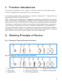
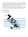
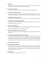
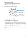
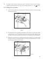
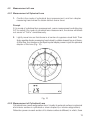
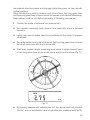
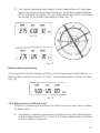
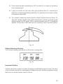
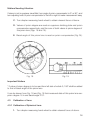
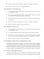
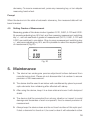
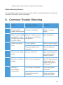
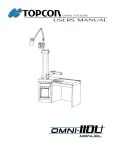
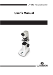
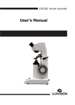
USER’S MANUAL LENSMETER
LM 300
Notification
Dear Users,
Thank you for your purchase of LM 300 Lensmeter. Please take time to read our
user’s manual carefully before use.
This guarantees you to make full use of this unit and prolongs the operation life of
this unit.
Precautions
If you have detected abnormal heat, smoke, noise or smell, immediately stop using
the product.
In the event of an abnormality, turn off the power and disconnect the power plug from
the power socket. Continuing to use the product may result in electric shock or fire.
Observe the instructions given below regarding the power cable:
•
•
•
•
•
•
Be sure to use the supplied or specified power cable.
Do not modify, forcibly bend, kink or pull the power cable.
When disconnecting the power cable from the AC outlet, be sure to hold the cable
by the plug.
Pulling the cable may cause wire breakage or shot circuit, resulting in fire or
electric shock.
Do not connect or disconnect the plug of the power cable to/from the AC outlet
using wet hands.
Doing so may result in electric shock.
Do not touch the product with wet hands while the power cable is connected
to the AC outlet.
Doing so may result in electric shock.
If the product will not be used for a long period, disconnect the power cable from
the power source. Leaving the cable connected to the power socket for a prolonged
period will consume electricity and may result in heating.
Content
1.
Function Introduction .....................................................................................4
2.
Working Principle Device ................................................................................4
3.
Functions ......................................................................................................5
4.
Operation ......................................................................................................8
5.
Maintenance ................................................................................................18
6.
Common Trouble Shooting ...........................................................................19
7.
Specifications ..............................................................................................20
1. Function Introduction
This device is divided into two models, A and B, in which A is standard model
and B is strengthened model with prism compensator.
In the following description, all sections or content marked with “*” before them are
specialized content of model B device.
Optic, machine and microelectronic integrated technologies are adopted in this device,
where, yellow liquid crystal display is available to achieve stable and precise measuring
result, proven to be an ideal device for having one’s eyesight tested for spectacles.
This device is applicable to all level measurement testing departments, spectacles
manufacturers, spectacles retail stores, hospital’s department of ophthalmology
and optical elements factories for conducting measurement of spherical lens diopter
of spectacles or lens, diopter of cylindrical lens, astigmatism axis angle of cylindrical
lens, diopter of bifocal lens, prism degree and prism basal angle.
2. Working Principle of Device
Fig. 1 Drawing of Optical Principle for Model A
Fig. 2 Drawing of Optical Principle for Model B
1. Light source
4. Diaphragm
7. Eyepiece Set
2. Mark Dividing Plate
5. Telescopic Objective
*8. Prism Compensator
3. Measurement Objective
6. Eyepiece Dividing Plate
4
This device consists of a coaxal optic system. Light sent forth from 1-Light Source
(LED) lights up 2-Mark Dividing Plate. After passing though 3-Measurement Objective
and 5-Telescopic Objective, 2-Mark Dividing Plate is imaged at position of 6-Eyepiece
Dividing Plate. At this time, through 7-Eyepiece Set, the distinct reticule images of
2-Mark Dividing Plate and 6-Eyepiece Dividing Plate can be seen.
During operation, put spectacle lens at the place of 4-Diaphragm (measurement
bearing scat), and turn diopter measuring hand-wheel and astigmatism turning handwheel so that distinct image of 2-Mark Dividing Plate is obtained. Now, the number
showing on the liquid crystal display screen is just the diopter value of this lens.
3. Functions
3.1
Main View (Fig3)
1
2
10
3
11
5
4
7
12
6
13
8
14
9
Fig. 3
5
1. Eyepiece
Eyepiece part is a screw type focusing unit with focusing range of ±5D,
adaptable to different eye-sights of human eyes.
*2. Prism Compensator
It is used to measure prism lens with prism degree bigger than 5∆.
3. Lens Pressing Mechanism
3 plastic pressing feet equipped with spring are used to press lens, able to
stably press lens with any shape of surface, with no damage to lens surface.
4. Measurement Bearing Seal
It can hold lens with any shape of surface with no damage to lens surface.
5. Astigmatism Turning Hand-Wheel
It is used to measure and locate astigmatism axis angle of cylindrical lens
and basal angle of prism lens.
6. Lens Pushing Board
When lens on the lens frame is conducted, lower part of lens frame (i.e. two
lens rings) shall contact the lens pushing board.
7. Diameter Indication Measuring Scale
When lens pushing board contacts edge of lens, it is possible to read lens
diameter.
8. Inclining Angle Adjusting Handle of Device
It is able to enable measurement user to adjust inclining angle of the device
easily, who can work with a comfortable posture. By rotating backwards
the adjusting handle, measurement user may tilt me device to a proper angle
according to specific status of work table, then simply lock up the handle.
9. Power Supply Socket
10. Dot-Making Mechanism
This mechanism consists of 3 identical dot-making pens connected into
a line, where, one in the middle is used to mark lens center, and connected
line of marking dots of 3 pens is used to mark astigmatism axis angle of lens
and basal angle of prism lens.
11. InkpadBox
It is used to store inkpad or ink for print.
6
12. Lens Pushing Hand Lever
It is used to move lens pushing board back and forth.
13. Diopter Measuring Hand-wheel
3.2
Drone and Eyepiece Dividing Plate (Fig.4)
15
16
Round-dot drone
Cross-line drone
Fig. 4
14. Liquid Crystal Display Screen
It displays diopter value of the measured lens.
15. Eyepiece Dividing Plate
Prism degree measuring scale and calibrated dial are marked on it. Prism
degree is marked with space of 1∆, where, integral prism degree is read
directly on the measuring scale, and decimal prism degree is read by
estimation from measuring scale. Calibrated dial 0 ~ 180° is marked with
space of 1°, and 180º ~ 360° with space of 5°.
16. Drone
Distinct image of mark dividing plate involves round-dot drone and cross-line
drone.
7
3.3
Liquid Crystal Display Screen (Fig 5)
Fig. 5
17. Reset Key RST
Pressing this key, it returns from other mode of measurement to the mode
ready to Operate.
18. Measurement Switching Key +/
When cylindrical lens is measured, pressing this key will realize switching of
light intensity of cylindrical lens degree. Pressing it once more, it returns to
the original state of display. It can be also used to set grade of measurement.
19. Measurement Switching Key S/C
Every time one presses this key, mode of measuring spherical lens or
cylindrical lens will be changed. Start-up of this machine defaults mode of
being ready to operate.
20. Adjustment Key ADJ
It is used to set grade of measurement.
4. Operation
4.1
Before Measurement
4.1.1 Preparation
1. Place the device on a working table with proper height to the extent that
the adjusted inclined angle of the device will result in comfortable measurement
for the user.
2. Put power supply wire into socket, and the device comes into mode of being
8
ready to operate (Fig.6). Turn diopter measuring hand-wheel. When digitals
appearon the display screen, it indicates the device is put in mode of spherical
lens measurement.
Important Prompt
Be sure to install measurement bearing seat correctly, otherwise it will result in imprecise
measurement.
Fig. 6
3. Adjustment of ocular visibility. To obtain precise and reliable measuring result,
ocular visibility shall be adjusted before measurement. The method is:
observe black reticule digitals of eyepiece dividing plate 6 in eyepiece visual
field. At the same time, the better way is to turn eyepiece cover in one way
(one-way rotation can eliminate influence caused by action of eye adjustment)
until the black reticule digitals become clearest.
4. Adjusting zero position of the device. Turn diopter measurement hand-wheel
to focus drone to clearest state. At this time, the display degree of spherical
lens is 0.00.
*5. If a prism compensator is provided, make sure that display of prism
compensator is “0” before measurement. (Fig.7)
Fig. 7
Matters Needing Attention
*1.
If diopter of testee’s eye is deep or it has astigmatism, measurement shall be
carried out only after he (she) wears spectacles for correcting visual acuity.
9
*2.
To obtain most precise measuring result, the better way is to turn diopter
measuring hand-wheel in one-way, with rotating direction of: - 25D
+25D.
4.1.2 Putting Lens in Position
1. Lens shall be placed on measurement bearing seat with concave facing
downwards (Fig.8).
Fig. 8
2. Lift upwards the lens pressing mechanism, then lower it to press lens; when
measurement is over, lift upwards the lens pressing mechanism again to the
top end so that lens pressing mechanism is hung tightly and automatically.
3. When lens on the frame is measured, lower part of frame (i.e. two lens rings)
should contact lens pushing board: turn lens pushing hand lever to push
out the lens pushing board (Fig.9).
Fig. 9
10
4.2
Measurement of Lens
4.2.1 Measurement of Spherical Lens
1. Confirm the mode of cylindrical lens measurement, and turn diopter
measuring hand-wheel to obtain distinct drone focus.
Prompt
If it is mode of cylindrical lens measurement, press measurement switching key
S/C to switch it to mode of cylindrical lens measurement, the device will sends
out sound of “DuDu” simultaneously.
2. Lightly move lens so that drone is at center of eyepiece visual field. Then
finely regulate diopter measuring hand wheel to obtain clearest focus of drone.
At this time, the number on the liquid crystal display screen is just the spherical
diopter of this lens (Fig. 10).
Fig. 10
4.2.2 Measurement of Cylindrical Lens
Cylindrical lens means astigmatism lens. Usually its external surface is spherical
and interior surface is cylindrical or drum-shaped (i.e. interior astigmatism).
Refractive power on each section of its interior surface is different, in which, there
11
are weakest refractive power and strongest refractive power on two mutually
vertical sections.
When this device is used to measure such kind of lens, two long green lines
and three long green lines of drone cannot be focused to be clear simultaneously.
Measurement shall be conducted according to following procedures:
1. Confirm the mode of spherical lens mesurement.
2. Turn diopter measuring hand-wheel so that round dot drone is focused
distinctly.
3. Lightly move lens to enable drone to be positioned at the center of eyepiece
visual field.
4. Turn astigmatism turning hand-wheel so that two long green lines of round
dot drone and cross-line drone are parallel.
5. Then finely regulate diopter measuring hand-wheel to obtain clearest focus
of two long green lines of round dot drone and cross-line drone (Fig.11).
Fig. 11
6. By pressing measurement switching key S/C, the device sends out sound of
“Du Du”, and it is switched to mode of cylindrical lens measurement (Fig.12).
12
7. Turn diopter measuring hand-wheel to obtain clearest focus of 3 long green
lines of round dot drone and cross-line drone. At this time, spherical diopter
(SPH), astigmatism degree (CYL) and astigmatism axis (AXIS) of this lens
are shown on the liquid crystal display screen (Fig. 13).
Fig. 12
Fig. 13
Matters Needing Attention
If it is required to do light degree switching, press measurement switching key +/,
then the device sends out sound of “DuDu”, and switched value is shown whereat
(Fig. 14).
Fig. 14
4.2.3 Measurement of Bifocal Lens
Function of measuring bifocal lens is to check how much near vision is added
to distant vision.
1. According to measuring procedures of spherical lens and cylindrical lens
in above stated Sections 5.2.1 and 5.2.2, measure distant vision of bifocal
lens (i.e. diopter of big lens).
13
2. Press measurement switching key S/C to switch it to mode of cylindrical
lens measurement.
3. Lightly move lens so that near vision part of bifocal lens (i.e. small lens) is
placed on measurement bearing seat (Fig. 15), and drone is moved to center
of eyepiece visual field.
4. Turn diopter measuring hand-wheel to obtain clearest focus of drone. At
this time, diopter degree value of this bifocal lens is shown on liquid crystal
display screen (Fig,16), where, SPH is spherical diopter, and CYL is additional
diopter. At this time, AXIS data have no meaning, which can be ignored.
Fig. 15
Matters Needing Attention
*Lift up lens pressing mechanism a little when moving lens.
Fig. 16
Important Matters
If drone cannot be moved to center of eyepiece visual field because of prism function
of lens, please use prism compensator to adjust drone to center of eyepiece visual
field so as to achieve better result of focus.
14
4.2.4 Measurement of Prism Lens
Measuring prism degree of prism lens consists of 2 ranges: 0 ~ 5 degrees and
5 ~ 20 degrees of prism.
1. In the range of 0 ~ 5 degrees of prism, the value is read directly on the
eyepiece dividing plate.
A. Place prism lens on the measurement bearing seat and turn diopter measuring
hand-wheel to make drone focus distinct.
B. Turn astigmatism turning hand-wheel so that the middle one of 3 long green
lines of cross-line drone passes through center of eyepiece dividing plate.
C. Prism degree and value of basal angle of prism lens are read on the eyepiece
dividing plate (Fig. 17).
Fig. 17 (2∆ basal angle 30°)
*2. In the range of 5 ~ 20 degrees of prism, prism compensator should be used.
A. Turn diopter measuring hand-wheel to obtain distinct focus of drone.
B. Turn adjusting knob of prism compensator so that drone is adjusted to a
proper position of eyepiece visual field.
15
Matters Needing Attention
If drone is not in eyepiece visual field, turn angle of prism compensator to 0° or 90°, and
turn adjusting knob of prism compensator to the left or right to make measurement easy.
C. Turn diopter measuring hand-wheel to obtain clearest focus of drone.
D. Values of prism degree are read on eyepiece dividing plate and prism
compensator respectively, and the sum of both values is prism degree of
this prism lens (Figs. 18 and 19).
E. Basal angle of this prism lens is read on prism compensator (Fig.19).
Fig. 18
Fig. 19
Important Matters
* If value of prism degree is to be read from left side of reticle 0, 180º shall be added
to that of basal angle of the prism lens.
It can be known from Fig. 18 and Fig. 19 that measured data of this prism lens are:
prism degree 16 ∆ and basal angle 210°.
4.3
Calibration of Lens
4.3.1 Calibration of Spherical Lens
1. Turn diopter measuring hand wheel to obtain clearest focus of drone.
16
2. Lightly move lens so that drone is at center of eyepiece visual field.
3. Make 3-dot mark using dot-making mechanism.
4.3.2 Calibration of Cylindrical Lens
1. Turn astigmatism turning hand-wheel to show required angle on the liquid
crystal display screen.
2. Turn diopter measuring hand wheel to obtain distinct focus of round dot
drone when SPH (spherical degree) is a big value.
3. Turn lens so that 3 long green lines of round dot drone and cross-line drone
are parallel.
4. Lightly move lens so that drone is at center of eyepiece visual field.
5. Make 3-dot mark using dot making mechanism.
4.3.3 Calibration of Prism Lens
1. Turn astigmatism turing hand-wheel to show required angle on the liquid
crystal display screen.
2. Turn diopter measuring hand wheel to obtain distinct focus of drone.
3. Move lens or use prism compensator so that the middle one of 3 long green
lines of cross-line drone passes through center of eyepiece visual field.
4. Make 3-dot mark using dot making mechanism.
4.3.4 Calibration of Optic Center of Assembled Two Lens
Put spectacles on the device. Choose any one of lens, and turn diopter measuring
hand wheel to enable focus of drone to be clearest and at center of eyepiece
visual field. Make central print-mark on this lens using dot making mechanism.
Repeat the operation to make central print mark on another lens. By the use
of vernier caliper, measure space between central print marks of two lenses.
4.4
Function of Automatic Dormancy
This device stops working for some 3 minutes. The auto-stop function: The lamp
at this time is not lighted, and device comes into a State of low consumption
17
dormancy. To resume measurement, press any measuring key, or turn diopter
measuring hand-wheel.
Prompt
When the device is in the state of automatic dormancy, the measured data will not
been liminated.
4.5
Setting Grades of Measurement
Measuring grades of this device involve 4 grades: 0.01D, 0.06D, 0.12D and 0.25D.
By pressing adjusting key ADJ first, and then pressing measurement switching
key +/-, one can see these 4 grades of measurement (0.01D, 0.06D, 0.12D and
0.25D) are switched in circulation. Stop to press measurement switching key
+/-, and press adjusting key ADJ, and it is possible to select the required grade
of measurement (Fig.20).
Fig. 20
5. Maintenance
1. The device has undergone precise adjustment before delivered from
manufacturing plant. Please do not disassemble it at random to ensure
precision of the measurement.
2. The device shall be used in an indoor well-conditioned dry place to prevent
optic elements from mildewing after affected with damp.
3. After using the device, keep it in a clean state and cover it with dustproof
shield.
4. The device shall be prevented from strong vibration or impact to avoid
damage and looseness of each component, thus to ensure precision of
measurement.
5. Always keep the device clean and do not touch surface of this optic part.
If dust or besmirch is found on it, be sure to clean it with absorbent cotton
18
dipped with mixed solution of ethanol and aether.
Matters Needing Attention
For cleaning the device, do not use organic solution such as paint thinner, otherwise
surface of the device will be damaged.
6. Common Trouble Shooting
No.
Failure
Reasons of Failure
Solutions
Liquid crystal
screen is not lighted
When ocular visibility
is adjusted, ocular
dividing plate cannot
he seen clearly
Lamp is not lighted
Switch on power
supply
Degree of testee’s eyes is
too deep or he (she) has
astigmatism
Wear spectacles
3
Drone can not be
seen
Lamp is lighted
Switch on power supply
Dustproof shield is not
removed
Take off dustproof
shield
4
Drone is not clearly
seen
Dust on optic lens
Excursion of drone
center
Lock screw is loosened
Clean it with absorbent
cottondipped with
cleaning solution
Take off measurement
bearing seat, and
adjust and tighten 3
lock screws
1
2
5
6
Shifting of
dot-making
mechanism
Limit screw is loosened
Adjust and tighten
limit screw
Connecting screw is
loosened
Adjust and tighten
connecting screw
19
7. Specifications
Range of diopter measurement
Spherical lens
-25D ~ +25D
Cylindrical lens
-9.99D ~ +9.99D
Space of readings
0.01D, 0.06D, 0.12D, 0.25D
Astigmatism axis angle of cylindrical lens
0 ~ 180° space of readings: 1°
Prism degree
Model A 0 ~ 5 ∆ space of readings: 1 ∆;
* Model B 0 ~ 20 ∆ space of readings: 1 ∆
Prism basal angle
0 ~ 180° space of readings: 1°
180° ~ 360° space of readings: 5°
Range of ocular visibility adjustment
-5D ~ +5D
Size of measured lens
Φ16mm - Φ80mm
Overall dimensions
320 mm (L) X 150 mm (W) X 450 mm (H)
Weight
Model A 4,9kg
* Model B 5 kg
Lamp of illumination
Φ5 super-lighting LED
Voltage
DC 6V/300mA
Power
1.5W
Temperature
-10º C ~ +50º C (in operation)
-20º C ~ +60° C (in storage/during transport)
Humidity
30 ~ 75% (in operation)
10 ~ 85%(in storage/during transport)
20
LUXVISION is not responsible or liable for indirect, special or consequential damages arising out of or in
connection with the use or performance of the product or damages with respect to any economic loss,
loss of property, loss of revenues or profits, loss of enjoyment or use, costs of removal or installation or
other consequential damages of whatsoever nature. Some states do not allow the exclusion or limitation
of incidental or consequential damages. Accordingly, the above limitation may not apply to you.
Every effort has been made to ensure the accuracy of this manual. However, LUXVISION, makes no
warranties with respect to the documentation and disclaims any implied warranties of merchantability
and fitness for a particular purpose. LUXVISION, Inc. shall not be liable for any errors or for incidental or
consequential damages in connection with the furnishing, performance, or use of this manual or the examples
herein. The information in this document is subject to change without notice.
21