1
Data sheet DS/WM–EN Rev. U
WaterMaster
Electromagnetic flowmeter
Measurement made easy
The perfect fit for all water
industry applications
One solution for all your needs
— designed for use in all water and waste water applications,
from sewage plants to distribution networks
State-of-the-art technology
— revolutionary data storage enables transmitter interchange
and commissioning without the need for re-configuration
— self-calibrating transmitter with ultra-low temperature
coefficient for highest accuracy
Versatile and simple configuration
— 'Through-the-Glass' (TTG) configuration eliminating the
need to remove the cover
— smart key based functionality
— 'Easy Setup' function
VeriMaster in situ verification software option
— enables the customer to perform in situ verification of the
flowmeter system
Unparalleled service ability
— fault-finding Help texts on the display
— minimized downtime with replaceable electronics cartridges
MID and OIML R49 approved with R49 self-checking
— Type-approved to accuracy Class 1 and Class 2 for any pipe
orientation and bidirectional flows
— Type P-approved continuous self-checking of the sensor
and transmitter to ensure the highest accuracy and long
term performance
Innovative sensors for all applications
— optimized full-bore series for optimum turndown / low
pressure drop, irrigation applications
— full-bore series for general-purpose water metering
applications
— reduced-bore series for high turn down applications, for
example, leakage
— buriable sensors eliminating the need for costly chamber
construction
HART, PROFIBUS DP and MODBUS
— Full system and PLC integration
WaterMaster
Electromagnetic flowmeter
The Company
Flow performance
ABB is an established world force in the design and
manufacture of instrumentation for industrial process control,
flow measurement, gas and liquid analysis and environmental
applications.
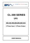
Utilizing its advanced filtering methods, the WaterMaster
improves accuracy even under difficult conditions. WaterMaster
has an operating flow range with ±0.4 % accuracy as standard
(±0.2 % optional) in both forward and reverse flow directions.
As a world leader in process automation technology our
worldwide
presence,
comprehensive
service
and
application-oriented know-how make ABB a leading supplier of
flow measurement products.
Easy and quick commissioning
Introduction
Setting the standard for the Water Industry
The WaterMaster range, available in sizes 10 to 2400 mm
(3/8 to 96 in.), is designed specifically for use on the many
diverse applications encountered in the Water and Waste-water
industry. The modular design concept offers flexibility,
cost-saving operation and reliability while providing a long
service life and exceptionally low maintenance.
Integration into ABB asset management systems and use of the
self-monitoring and diagnostic functions increase the plant
availability and reduce downtimes.
VeriMaster – the verification tool
An easy-to-use utility, available through the infra red service port,
it uses the advanced self-calibration and diagnostic capability of
WaterMaster, coupled with fingerprinting technology, to
determine the accuracy status of the WaterMaster flowmeter to
within ±1 % of its original factory calibration. VeriMaster also
supports printing of calibration verification records for regulatory
compliance.
'Fit-and-Flow' data storage inside WaterMaster eliminates the
need to match sensor and transmitter in the field. On initial
installation, the self-configuration sequence automatically
replicates into the transmitter all calibration factors, meter size
and serial numbers, as well as customer site-specific settings,
eliminating the potential for error.
Intuitive, convenient navigation
The 'Easy Setup' function reliably guides unpracticed users
through the menu step by step. The smart key based
functionality makes handling a breeze – it's just like using a cell
phone. During configuration, the permissible range of each
parameter is indicated on the display and invalid entries are
rejected.
Universal transmitter – powerful and flexible
The backlit display can be rotated easily without the need for
tools. The contrast is adjustable and the display
fully-configurable. The character size, number of lines and
display resolution (number of decimal points) can be set as
required. In multiplex mode, several different display options can
be pre-configured and invoked one after the other.
The smart modular design of the transmitter unit enables easy
disassembly without the need to unscrew cables or unplug
connectors. HART is used as the standard communications
protocol. Optionally, the transmitter is available with PROFIBUS
DP or MODBUS communication.
Assured quality
WaterMaster is designed and manufactured in accordance with
international quality procedures (ISO 9001) and all flowmeters
are calibrated on nationally-traceable calibration rigs to provide
the end-user with complete assurance of both quality and
performance of the flowmeter.
Diagnostic functions
Using its diagnostic functions, the flowmeter monitors both its
own operability and the process. Limit values for the diagnostic
parameters can be set locally. When these limits are exceeded,
an alarm is tripped. In the event of an error,
diagnostic-dependent help text appears on the display and this
considerably simplifies and accelerates the troubleshooting
procedure.
In accordance with NAMUR NE107, alarms and warnings are
classified with the status of 'Maintenance Required', 'Check
Function', 'Failure' and 'Out of Specification'.
2 DS/WM–EN Rev. U
WaterMaster
Electromagnetic flowmeter
WaterMaster – always the first choice
Overview of the WaterMaster
WaterMaster sets the standard for the water industry. The
specification, features and user benefits offered by this range are
based on ABB's worldwide experience in this industry and they
are all targeted specifically to the industry's requirements.
A wide range of features and user benefits are built into
WaterMaster as standard:
Submersible and buriable
WaterMaster sensors have a rugged, robust construction to
ensure a long, maintenance-free life under the arduous
conditions experienced in the Water and Waste Industry. The
sensors are, as standard, inherently submersible (IP68, NEMA
6P), thus ensuring suitability for installation in chambers and
metering pits that are susceptible to flooding.
A unique feature of the WaterMaster sensors is that sizes DN40
to DN2400 (11/2 to 96 in. NB) are buriable; installation simply
involves excavating to the underground pipe, fitting the sensor,
cabling back to the transmitter and then backfilling the hole.
bi-directional flow
unique self-calibrating transmitter (patented) for the
ultimate in stability and repeatability
OIML-type continuous self-checking, with alarms,
ensures both sensor and transmitter accuracy
true electrode and coil impedance measurement
comprehensive simulation mode
universal switch-mode power supply
(options are available for AC and DC supplies)
comprehensive self-diagnostics compliant with
NAMUR NE107
programmable multiple-alarm capability
bus options: HART (4 to 20 mA), PROFIBUS DP (RS485),
MODBUS (RS485)
3 configurable pulse / frequency and alarm outputs
advanced infrared service port supports remote HMI,
HART, cyclic data out and parameter download
VeriMaster in situ verification software available as option
read-only switch and ultra-secure service password for
total security
The WaterMaster family
DS/WM–EN Rev. U 3
WaterMaster
Electromagnetic flowmeter
OIML / MID approved
Superior control through advanced sensor design
WaterMaster has been type tested and Internationally approved
to the highest accuracy class 1 and 2 for cold and hot potable
water meters – OIML R49-1 (Organisation Internationale de
Métrologie Légale). For full details, OIML R49 is available to
download from www.oiml.org. Its requirements are very similar
to other International standards, such as EN14154 and
ISO4064.
The innovative, patented octagonal sensor design improves flow
profile and reduces up- and down-stream piping requirements
for the most commonly used sizes of 40 to 200 mm (11/2 to
8 in.). This optimized full bore meter provides impressive results
in the most difficult of installation requirements.
WaterMaster has been assessed by type approval at the
National Measurement Office (NMO) to OIML R49 and passed
to the very highest accuracy designations for sizes DN40 to
DN200 (11/2 to 8 in. NB).
The approval is for:
Class 1 and Class 2 accuracy (calibration option)
Environmental class T50 for water temperatures of
0.1 to 50 °C (32.18 to 122 °F)
Electromagnetic Environment E2 (10 V/m)
Any pipe orientation
5 Diameters upstream pipe
0 Diameters downstream pipe
Pressure Loss Class <0.25 bar (3.62 psi)
Integral or remote transmitter (<200 m [<656 ft.] cable)
DN40 to DN200 (11/2 to 8 in. NB), bi-directional flow
A major advance in WaterMaster is the self-checking capabilities
that meet and exceed the R49 requirements and is the first
electromagnetic flowmeter to be approved to OIML Type P
permanent self checking during normal operation (not just at
startup) and alarm indication for:
transmitter and sensor status, with an accuracy alarm
program ROM and RAM status
double, independent storage of totalizer values, in both
the sensor and transmitter non-volatile memories
display test
The OIML R49-1 certificate of conformity is available from:
http://www.abb.com/product/seitp330/b42ec2377d3293cd
c12573de003db93b.aspx
WaterMaster is also approved under the EU Measuring
Instruments Directive (MID) 2004/22/EC, that covers putting into
use water flowmeters for certain applications. MID WaterMaster
is secured against tamping and is available as an option, along
with fingerprinting for ABB VeriMaster in situ verification product,
with certificate printout to ±1 % accuracy.
WaterMaster certificates of EC type-examination of a measuring
instrument are available from:
http://www.abb.com/product/seitp330/b42ec2377d3293cd
c12573de003db93b.aspx
4 DS/WM–EN Rev. U
WaterMaster sensors are also available in reduced-bore
geometries giving the ultimate in low-flow performance with a
very high turn-down range.
The unique design of the reduced-bore sensor conditions the
flow profile in the measuring section so that distortions in the
flow profile, either upstream or downstream, are flattened. The
result is excellent in situ flowmeter performance, even with very
bad hydraulic installation conditions.
WaterMaster
Electromagnetic flowmeter
Specification
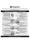
WaterMaster specification to OIML R49 Class 1
DN100 (4 in. NB)
WaterMaster Class 1
Specification
Error (%)
Typical Meter
Performance
±0.2 % ±0.9 mm/s
whichever is the greater
Around Q2 the
performance is
±0.7 mm/s
OIML R49 Class 1
Accuracy Limits
0.1 (0.44)
1.0 (4.4)
10 (44)
100 (440)
1000 (4402)
Flowrate m3/h (GPM)
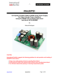
WaterMaster specification to OIML R49 Class 2
DN100 (4 in. NB)
Error (%)
WaterMaster Class 2
Specification
Typical Meter
Performance
±0.4 % ±0.9 mm/s
whichever is the greater
±0.4 %
OIML R49 Class 2
Accuracy Limits
Q3
0.1 (0.44)
1.0 (4.4)
10 (44)
100 (440)
1000 (4402)
Flowrate m3/h (GPM)
Although OIML R49 does not define the flow accuracy below Q1, WaterMaster continues to measure flow at lower flow rates down to
a cutoff velocity of ±5 mm/s (±0.2 in./s). The accuracy between cutoff and Q1 is typically ±0.9 mm/s (±0.04. in./s).
DS/WM–EN Rev. U 5
WaterMaster
Electromagnetic flowmeter
WaterMaster optimized full-bore meter (FEV) / full-bore meters (FEF, FEW) flow performance – m3/h
Standard Calibration – 0.4 % Class 2
High Accuracy Calibration – 0.2 % Class 1
DN
Q4
Q3
Q0.4%
Q2
Q1
Q0.2%
Q2
Q1
10
3.1
2.5
0.167
0.013
0.008
0.31
0.02
0.012
15
7.88
6.3
0.42
0.032
0.02
0.79
0.05
0.03
20
12.5
10
0.67
0.05
0.032
1.25
0.08
0.05
25
20
16
1.1
0.08
0.05
2
0.13
0.08
0.13
32
31.25
25
1.67
0.13
0.08
3
0.20
40*
50
40
4.2
0.2
0.13
6
0.32
0.2
50*
79
63
4.2
0.32
0.20
7.9
0.5
0.32
65*
125
100
6.7
0.5
0.32
12.5
0.8
0.5
80*
200
160
10.7
0.81
0.51
16
1.3
0.8
100*
313
250
16.7
1.3
0.79
25
2
1.25
125*
313
250
16.7
1.3
0.79
25
2
1.25
150*
788
630
42
3.2
2.0
63
5
3.2
200*
1,250
1,000
67
5.1
3.2
100
8
5
250
2,000
1,600
107
8.1
5.1
160
13
8
300
3,125
2,500
167
12.7
7.9
250
20
12.5
350
5,000
4,000
267
20.3
12.7
400
32
20
400
5,000
4,000
267
20.3
12.7
400
32
20
450
7,875
6,300
420
32
20
630
50
32
500
7,875
6,300
420
32
20
630
50
32
600
12,500
10,000
667
51
32
1000
80
50
700
20,000
16,000
1600
102
64
1600
160
100
750
20,000
16,000
1600
102
64
1600
160
100
30 in (760)
20,000
16,000
1600
102
64
1600
160
100
800
20,000
16,000
1600
102
64
1600
160
100
900
31,250
25,000
2500
160
100
2500
250
156
1000
31,250
25,000
2500
160
100
2500
250
156
42 in
31,250
25,000
2500
160
100
2500
250
156
1100
31,250
25,000
2500
160
100
2500
250
156
1200
50,000
40,000
4000
256
160
4000
400
250
1350
78,750
63,000
6300
403
252
6300
630
394
1400
78,750
63,000
6300
403
252
6300
630
394
1500
78,750
63,000
6300
403
252
6300
630
394
60 in (1500)
78,750
63,000
6300
403
252
6300
630
394
1600
78,750
63,000
6300
403
252
6300
630
394
1650
78,750
63,000
6300
403
252
6300
630
394
1800
125,000
100,000
10000
640
400
10000
1000
625
1950
125,000
100,000
10000
640
400
10000
1000
625
2000
125,000
100,000
10000
640
400
10000
1000
625
2200
200,000
160,000
16000
1024
640
16000
1600
1000
2400
200,000
160,000
16000
1024
640
16000
1600
1000
* OIML R49 Certificate of Conformance to Class 1 and Class 2, with OIML R49 and MID versions available.
Note. OIML R49–1 allow Class 1 only for meters with Q3 100 m3/h. Meters outside this range have been tested and conform
to Class 1.
6 DS/WM–EN Rev. U
WaterMaster
Electromagnetic flowmeter
WaterMaster optimized full-bore meter (FEV) / full-bore meters (FEF, FEW) flow performance – gal/min
Standard Calibration 0.4 % Class 2
NPS/NB (DN)
High Accuracy Calibration 0.2 % Class 1
Q4
Q3
Q0.4%
Q2
Q1
Q0.2%
Q2
Q1
3
13.8
11
0.73
0.06
0.035
1.38
0.09
0.053
1
34.7
27.7
1.85
0.14
0.09
3.48
0.22
0.14
3
/4 (20)
55
44
2.94
0.22
0.14
5.5
0.35
0.22
1 (25)
88
70.4
4.7
0.35
0.22
8.8
0.57
0.35
1 1/4 (32)
137.6
110
7.3
0.57
0.35
13.2
0.88
0.57
1 1/2 (40)
220
176
18.5
0.89
0.56
26.4
1.41
0.88
2 (50)
347
277
18.5
1.41
0.88
34.7
2.22
1.39
2 1/2 (65)
550
440
29.4
2.24
1.40
55.0
3.52
2.20
3 (80)
881
704
47.0
3.58
2.24
70.4
5.64
3.52
4 (100)
1,376
1,101
73.4
5.59
3.49
110
8.81
5.50
5 (125)
1,376
1,101
73.4
5.59
3.49
110
8.81
5.50
6 (150)
3,467
2,774
185
14.1
8.81
277
22.2
13.9
8 (200)
5,504
4,403
294
22.4
14.0
440
35.2
22.0
10 (250)
8,806
7,045
470
35.8
22.4
704
56.4
35.2
12 (300)
13,759
11,007
734
55.9
34.9
1,101
88.1
55.0
14 (350)
22,014
17,611
1,174
89.5
55.9
1,761
141
88.1
16 (400)
22,014
17,611
1,174
89.5
55.9
1,761
141
88.1
18 (450)
34,673
27,738
1,849
141
88.1
2,774
222
139
20 (500)
34,673
27,738
1,849
141
88.1
2,774
222
139
24 (600)
55,036
44,029
2,935
224
140
4,403
352
220
27/28* (700)
88,057
70,446
7,045
451
282
7,045
704
440
29 (750)
88,057
70,446
7,045
451
282
7,045
704
440
30 (760)
88,057
70,446
7,045
451
282
7,045
704
440
32 (800)
88,057
70,446
7,045
451
282
7,045
704
440
36 (900)
137,590
110,072
11,007
704
440
11,007
1,100
688
39/40* (1000)
137,590
110,072
11,007
704
440
11,007
1,100
688
42 (1050)
137,590
110,072
11,007
704
440
11,007
1,100
688
44 (1100)
137,590
110,072
11,007
704
440
11,007
1,100
688
48 (1200)
220,143
176,115
17,611
1,127
704
17,611
1,761
1,101
52 (1350)
346,726
277,381
27,738
1,775
1,110
27,738
2,773
1,733
54 (1400)
346,726
277,381
27,738
1,775
1,110
27,738
2,773
1,733
60 (1500)
346,726
277,381
27,738
1,775
1,110
27,738
2,773
1,733
66 (1600)
346,726
277,381
27,738
1,775
1,110
27,738
2,773
1,733
68 (1650)
346,726
277,381
27,738
1,775
1,110
27,738
2,773
1,733
77 (1800)
550,358
440,287
44,029
2,818
1,761
44,029
4,403
2,752
77 (1950)
550,358
440,287
44,029
2,818
1,761
44,029
4,403
2,752
78 (2000)
550,358
440,287
44,029
2,818
1,761
44,029
4,403
2,752
78 (2000)
550,358
440,287
44,029
2,818
1,761
44,029
4,403
2,752
84 (2200)
880,573
704,459
70,446
4,509
2,818
70,446
7,045
4,403
96 (2400)
880,573
704,459
70,446
4,509
2,818
70,446
7,045
4,403
/8 (10)
/2 (15)
*Size is dependent on flange specification
WaterMaster reduced-bore meter (FER) flow performance – m3/h (gal/min)
Class 2 specification
Size
Q4
Q3
Q0.4 %
Q2
Class 1 specification
Q1
m3 / h (Ugal / min) m3 / h (Ugal / min) m3 / h (Ugal / min) m3 / h (Ugal / min) m3 / h (Ugal / min)
R
Q0.2 %
Q2
Q1
m3 / h (Ugal / min) m3 / h (Ugal / min) m3 / h (Ugal / min)
R
mm
in.
40
11/2
31 (138)
25 (110)
0.83 (1.05)
0.063 (0.28)
0.04 (0.18)
630
1.7 (7.48)
0.1 (0.44)
0.063 (0.28)
400
50
2
50 (220)
40 (176)
1.0 (4.40)
0.1 (0.44)
0.063 (0.28)
630
2.0 (8.8)
0.16 (0.7)
0.1 (0.44)
400
65
21/2
79 (347)
63 (277)
1.6 (7.04)
0.16 (0.7)
0.1 (0.44)
630
3.2 (10.56)
0.25 (1.1)
0.16 (0.7)
400
80
3
125 (550)
100 (440)
2.0 (8.80)
0.25 (1.1)
0.16 (0.7)
630
4.0 (17.6)
0.4 (1.76)
0.25 (1.1)
400
100
4
200 (880)
160 (704)
3.2 (10.56)
0.41 (1.8)
0.25 (1.1)
630
6.4 (28)
0.64 (2.8)
0.4 (1.76)
400
125
5
200 (880)
160 (704)
3.2 (10.56)
0.41 (1.8)
0.25 (1.1)
630
6.4 (28)
0.64 (2.8)
0.4 (1.76)
400
150
6
500 (2200)
400 (1760)
8.0 (35.20)
1.0 (4.4)
0.63 (2.77)
630
16 (70.4)
1.6 (7)
1.0 (4.4)
400
200
8
788 (3470)
630 (2770)
13.0 (57.2)
1.6 (7.04)
1.0 (4.4)
630
25 (110)
2.5 (11)
1.6 (7)
400
250
10
1250 (5500)
1000 (4400)
20 (88)
2.5 (11.01)
1.6 (7)
630
40 (176)
4.0 (17.6)
2.5 (11)
400
300
12
2000 (8810)
1600 (7045)
32 (140.8)
4.1 (18.05)
2.5 (11)
630
64 (281.6)
6.4 (28)
4.0 (17.6)
200
350
14
2000 (8810)
1600 (7045)
32 (140.8)
6.4 (28.18)
4.0 (17.6)
400
64 (281.6)
12.8 (56)
8.0 (35.2)
200
375
15
2000 (8810)
1600 (7045)
32 (140.8)
6.4 (28.18)
4.0 (17.6)
400
64 (281.6)
12.8 (56)
8.0 (35.2)
200
400
16
3125 (13760)
2500 (11007)
50 (220)
10 (44)
6.3 (27.7)
400
100 (440)
20 (88)
12.5 (55)
200
450
18
3125 (13760)
2500 (11007)
50 (220)
10 (44)
6.3 (27.7)
400
100 (440)
20 (88)
12.5 (55)
200
500
20
5000 (22014)
4000 (17610)
80 (352)
16 (70.45)
10 (44)
400
160 (70.4)
32 (141)
20 (88)
200
600
24
7875 (34670)
6300 (27740)
126 (554.4)
25.2 (110.9)
15.8 (70)
400
252 (1108)
50.4 (222)
31.5 (138.7)
200
DS/WM–EN Rev. U 7
WaterMaster
Electromagnetic flowmeter
Specification – sensor
Physical specification
Wetted parts
Functional specification
Electrode material
Stainless steel 316 L / 316 Ti
Pressure limitations
As per flange rating – non approved
PN16 for OIML R49, MID Approved
Super-austenitic steel
Pressure equipment directive 97/23/EC
This product is applicable in networks for the supply, distribution and
discharge of water and associated equipment and is therefore
exempt.
Temperature limitations
Hastelloy® C-22 and Hastelloy C4
(other electrode materials available on request)
Potential equalizing rings
Minimum of 1 recommended
Lining material / potable water approvals
Ambient temperature
Remote transmitter –20 to 70 °C (–4 to 158 °F)
Integral transmitter
Potable Water Approvals
–20 to 60 °C (–4 to 140 °F)
Process temperature See table below.
0.1 to 50 °C (32.2 to 122 °F) – OIML R49 T50
Approved
Code
Size Range
Liner
WRAS
FEW1
DN10 – 32
(3/8 – 11/4 in. NB)
PTFE
4
FEW3
DN10 – 600
(3/8 – 24 in. NB)
PTFE
FEW3
DN40 – 2400
Elastomer
(11/2 – 96 in. NB)
FEW3
DN40 – 2400
(11/2 – 96 in. NB)
Hard
rubber
4
FEV
DN40 – 200
(11/2 – 8 in. NB)
Polypropylene
4
FEF
DN250 – 600
(10 – 24 in. NB)
Elastomer
4
FEF
DN250 – 600
(10 – 24 in. NB)
Hard
rubber
4
FER
DN40 – 600
Elastomer
(11/2 – 24 in. NB)
Medium temperature °C (°F)
Code
FEF, FEW3
FEW1
FEW3
Lining
Flange material
Minimum
Maximum
Carbon steel
–10 (14)
90 (194)
Stainless steel
–10 (14)
90 (194)
Hard rubber
Carbon steel
–10 (14)
130 (266)
Stainless steel
–25 (–13)
130 (266)
Carbon steel
–10 (14)
130 (266)
Stainless steel
–10 (14)
130 (266)
Carbon steel
–5 (23)
80 (176)
PTFE
PTFE
FEW3
Elastomer
FEF, FER
Elastomer
FEV
Polypropylene
Stainless steel
–5 (23)
80 (176)
–6 (21)
70 (158)
–6 (21)
70 (158)
Carbon steel
IP rating
IP68 (NEMA 6) to 7 m (20 ft.) depth
Note. Not sizes DN10 to DN32 (3/8 – 11/4 in. NB)
IP67 (NEMA 4X) – DN10 to DN32 (3/8 – 11/4 in. NB)
Buriable (sensor only)
FEV, FEF and FEW – DN450 to 2400 (18 to 96 in. NB)
to 5 m (16 ft.) depth
Conductivity
>5µS cm–1
Transmitter mounting
Integral (not FEF) or remote
Electrical connections
20 mm glands
1
/2 in. NPT
20 mm armored glands
Sensor cable
ABB WaterMaster cable available in two forms –
standard and armored
Maximum length 200 m (660 ft.)
8 DS/WM–EN Rev. U
WRAS
ACS DVGW
60°C
NSF
4
AZ/
NZS
4020
4
4
NSF approved
material
4
4
NSF-61
4
4
4
NSF-61
4
4
NSF approved
material
4
4
4
4
4
4
*Size is dependent on flange specification
Lining protection plates
Not required
Installation conditions (recommended)
FEW / FEF
FEV
FER
Straight pipe requirements
Upstream
Downstream
5 x DN
2 x DN
5x DN
0 x DN
0 x DN
0 x DN
Pressure loss
Negligible at Q3
All full bore meters
<0.25 bar (<3.62 psi) at Q3 FEV (DN40 to 200 [11/2 to 8 in. NB])
<0.63 bar (<9.13 psi) at Q3 FER (DN40 to 600 [11/2 to 24in. NB])
WaterMaster
Electromagnetic flowmeter
Non-wetted parts
Flange material
Carbon steel
DN20 to DN2400 (3/4 to 96 in. NB)
Stainless steel
SG iron
DN10 to DN2400 (3/8 to 96 in. NB)
FEV – DN40 to DN150 [1 1/2 to 6 in. NB)
FER – DN40 to DN150 [1 1/2 to 6 in. NB)
Housing material
Carbon steel
FEV – DN40 to 200 (11/2 to 8 in. NB)
Plastic
Aluminium
FEW – DN450 to 2400 (18 to 96 in. NB)
FEF – DN250 to 600 (10 to 24 in. NB)
FEW – DN10 to 400 (3/8 to 16 in. NB)
Terminal box material
Polycarbonate
Cable gland material
Plastic, brass
Paint specification
Paint coat 70 µm thick RAL 9002 (light grey)
DS/WM–EN Rev. U 9
WaterMaster
Electromagnetic flowmeter
Specification – transmitter
Functional specification
Power supply
Mains
Low voltage
DC
85 to 265 V AC @ <7 VA
24 V AC +10 % /–30 % @ <7 VA
24 V ±30 % @ <0.4 A
Supply voltage fluctuations within the specified range have no
effect on accuracy
Digital Outputs (3)
Rating 30 V @ 220 mA, open collector, galvanically isolated *
Maximum output frequency 5250 Hz
1 off dedicated to Alarm / Logic, programmable function
2 off configurable to either Pulse / Frequency or Alarm/Logic function
Current output – HART FEX100 variant
4 to 20 mA or 4 to 12/20 mA, galvanically isolated *
Maximum loop resistance 750
HART protocol Version 5.7 (HART registered)
Signal levels compliant with NAMUR NE 43 (3.8 to 20.5 mA)
Low alarm 3.6 mA, High alarm 21.8 mA
Additional accuracy
±0.1 % of reading
Temperature coefficient: typically <±20 ppm/°C
RS485 Communications – PROFIBUS FEX100-DP variant
Registered name: FEX100-DP
RS485 (9.6kbps to 1.5Mbps), galvanically isolated
DPV0, DPV1
PA Profile 3.01
Environmental protection
Humidity: 0 to 100 %
Rating: IP67 (NEMA 4X) to 1m (3.3 ft.) depth
Tamper-proof security
Write access prevented by internal switch combined with
external security seals for MID applications
Languages
English, French, German, Italian, Spanish, Polish
Infrared service port
USB adapter (accessory), USB 1.1. and 2.0 compatible
Driver software for Windows 2000, XP, 7 (32-bit) and Vista
Housing material
Powder-coated aluminium with glass window
Paint specification
Paint coat 70 µm thick RAL 9002 (light grey)
Transmitter vibration testing
Vibration level: 7 m/s2
Frequency range: 20 to 150 Hz
No. of sweeps in 3 orthogonal planes: 20
Undetectable shift in transmitter span or zero performance
Hazardous approvals (HART variant only)
FM & FMc Class 1 Div 2
(FM listing NI / 1 / 2 / ABCD / T4, S / II, III / 2 / FG /T4,
Ta=60C; Type 4X, IP67 – for transmitter and integral mounting
Ta=70C, Type 6P, IP68 – for remote sensor type,
IP67 on DN10 to 32 [3/8 to 11/4 in.NB])
(FMc listing NI / 1 / 2 / ABCD / T4, DIP / II, III / 2 / FG /T4,
Ta=60C; Type 4X, IP67 – for transmitter and integral mounting
Ta=70C, Type 6P, IP68 – for remote sensor type, IP67 on
DN10 to 32 [3/8 to 11/4 in.NB])
Standard idents: 9700, 9740, 9741
FET, FEV, FEW and FEF DN700 to 2200 (27/28* to 84 in. NB) only
FEX100-DP specific ident: 3431
*Size is dependent on flange specification
3 Concurrent MS2 master connections
RS485 Communications – MODBUS FEX100-MB variant
MODBUS RTU protocol
RS485 (9.6kbps to 115.2kbps), galvanically isolated
Electrical connections
20 mm glands 1/2 in. NPT, 20 mm armored glands
Temperature limitations
Ambient temperature –20 to 60 °C (–4 to 140 °F)
Temperature
Typically <±10 ppm/°C @ Vel 0.5 mls
coefficient
ATEX* Zone 2, 21 & 22
II 3 G Ex nA IIC T5 Gc
II 2 D Ex tb IIIC T100°C Db
TA = –20°C to +60°C (integral transmitter)
TA = –20°C to +70°C (remote sensor)
IECEx* Zone 2, 21 & 22
Ex tb IIIC T100°C Db
Ex nA IIC T5 Gc
TA = –20°C to +60°C (integral transmitter)
TA = –20°C to +70°C (remote sensor)
*FEW, FEV, FET and FEF 700 (27/28 in. NB) only
Declaration of Conformance
Copies of CE certification will be available on request.
WaterMaster has OIML R49 Certificate of Conformity to accuracy
class 1 and 2 (FEV DN40 to 200 [11/2 to 8 in.NB]). Copies of accuracy
certification are available on request.
WaterMaster (FEV DN40 to 200 [11/2 to 8 in.NB]) has been type
examined under directive MID 2004/22/EC, Annex MI-001. Copies of
this certificate are available on request.
* When installed, do not leave galvanically isolated circuits (pulse and
current) floating.
10 DS/WM–EN Rev. U
WaterMaster
Electromagnetic flowmeter
Transmitter connections
Transmitter terminal connections overview
This section is intended to give an overview of installation of a flowmeter. For Installation requirements, technical information and
Health and safety precautions – refer to the User Guide OI/FET100–EN.
Test Points for
Output Connections
AC / DC Power
Supply Terminal
Sensor
Cable Terminal
Output
Connections Terminal
Backplane
Internal Earth
(Alternative PE)
Internal Earth
(Alternative PE)
External Earth
Power Cable
Output Connections
Output Connections
Sensor Cable
Cable gland / conduit entry (Remote transmitter shown)
Sensor cable terminal connections and recommended cable lengths
Cut cables to 60 mm (2.35 in.)
Cut cables to 70 mm (2.75 in.)
M1
Brown
M2
Red
D1/TFE
Orange
D2
Yellow
3
Green
(Sleeve)
S2
Blue
(Screen)
E2
E1
Blue
Violet
(*Signal) (*Signal)
S1
Violet
Screen)
SCR
Screen
**Drain Wire (Twisted
with screen from
D1/TFE – Orange
and D2 – Yellow)
See above for cable preparation
requirements before connecting cable
*Inner wire
**For cathodically-protected systems (or if the transmitter enclosure does not have an earth
screw) connect the drain wire to terminal SCR.
Sensor cable connections at transmitter terminal block – remote transmitter
DS/WM–EN Rev. U 11
WaterMaster
Electromagnetic flowmeter
Power supply connections
AC power supply
Power Supply Indicator LED
*AC Fuse F1 250 mA Type T
(see table below for suppliers)
Internal Earth
Screws**
**Can be used as a
Protective Earth (PE)
if required by
national standards
Brown
Blue
Green / Yellow
AC power via a suitable
isolator and fuse
*Fuse Supplier
ABB
Fuse Part Number
B20411
Bussmann
BK/ETF 250 mA
Wickmann
19372 K250mA
External Earth Screw
2
>4 mm (<10 AWG) Copper Wire
Transmitter Label
AC power supply connections
DC (and low voltage AC) power supply
Power Supply Indicator LED
*DC Fuse F2 2 A Type T
(see table below for suppliers)
Internal Earth
Screws
Red
Black
Green / Yellow
External Earth
>4 mm2 (<10 AWG) Copper Wire
*Fuse Supplier
ABB
Fuse Part Number
B20412
Bussmann
BK/ETF2A
Wickmann
19372 K2A
DC (or Low Voltage AC) power
via suitable Isolator and fuse
Transmitter Label (DC)
DC (and low voltage AC) power supply connections
12 DS/WM–EN Rev. U
WaterMaster
Electromagnetic flowmeter
Configuration DIP switches
Three configuration DIP switches are mounted on the
transmitter backplane board.
These are factory-set as follows:
Remote transmitter – all OFF
Transmitter module identification
Note. The communications bus type is HART FEX100 if not
specified on the transmitter module label. An example of the
PROFIBUS FEX100-DP variant transmitter module label is
shown below.
Integral transmitter – SW3 ON
For MID-compliant flowmeters the read-only / MID protection
switch is set to 'ON' to ensure the meter is secure from
tampering.
For HART software versions prior to 01.02.XX, this switch (set
after commissioning) prevents login via the keypad or bus at any
security level.
From HART software version 01.03.XX onwards and for all
PROFIBUS software versions, on MID meters, all
metrological-related parameters are locked and inaccessible at
the Service level. Standard and Advanced user level parameters
can still be modified via the HMI or bus.
PROFIBUS FEX-100P Label
Configuration
DIP Switches
OFF
ON
SW3 SW2 SW1
Red Label on DC
(and Low Voltage AC)
Converter Module
DIP Switch Functions
SW1 – Read-only / MID Protection
SW2 – (Future Product)
SW3 – Internal Sensor Memory
Black Label on AC Converter Module
Configuration DIP switches
Transmitter module identification
DS/WM–EN Rev. U 13
WaterMaster
Electromagnetic flowmeter
Output connections
Frequency outputs
Alarm outputs
PLC or Datalogger
XX XX XX XX 42 41 51 61
52
62
Terminal connection IDs are
HART- / PROFIBUS- / MODBUSvariant dependent
COM DO3
COM DO1 DO2
Alarm 1
PLC / Datalogger connections
Note. Digital outputs DO1 and DO2 are polarity sensitive.
The common (negative) connection for these outputs is
designated 'COM'.
Bell
DC Supply
COM
+
XX XX XX XX 42 41 51 61
52
62
–
Terminal connection IDs are
HART- / PROFIBUS-variant
dependent
DO1 DO2 DO3
and / or
Horn
Alarm 2
Forward Flow Output (DO1)
Counter / Totalizer
DC
Supply
1 2 34 56
–
+
Note.
XX XX XX XX 42 41 51 61
52
62
COM
DO1
and / or
DO2
1 2 34 56
Reverse Flow
Output (DO2)
Counter / Totalizer
Normal alarm / logic output is from DO3 (terminal 61).
DO1 (41) and DO2 (51) can also be configured as
alarms if required but are then NOT available as
frequency / pulse
outputs
as
shown
in
Electromechanical
connections
and
Telemetry / Electronic
counters
connections,
opposite.
Bell and horn shown for example only. Any suitable
alarm device may be used (for example, lamp, siren,
buzzer etc.).
Electromechanical connections
Forward Flow Output (DO1)
Counter / Totalizer
COM
DO1
DO2
+
Alarm 1
and / or
DC Supply
Timer Switch
–
1 2 34 56
+
Reverse Flow
Output (DO2)
Counter / Totalizer
+
XX XX XX XX 42 41 51 61
52
62
1 2 34 56
XX XX XX XX 42 41 51 61
52
62
COM
DO1
DO2
–
–
R
Alarm 2
Relay
and / or
Telemetry / Electronic counters connections
Note. Relay and timer switch shown for example only.
14 DS/WM–EN Rev. U
WaterMaster
Electromagnetic flowmeter
PLC interface
Current output (4 to 20 ma) – HART (FEX100) variant
24 V
PLC
+
Typically
1k
1W
XX XX XX XX 42 41 51 61
52
62
Fwd +
DC Supply
DO1
Rev +
DO2
–
COM
+
–
Refer to IM/WMP for HART-Protocol
communication details
Current output (4 to 20 mA) – HART (FEX100) variant
RS485 communications – PROFIBUS (FEX100-DP) and
MODBUS (FEX100-MB) variants
+
Com
XX XX XX XX 42 41 51 61
52
62
DC Supply
PROFIBUS / MODBUS RS485
A1 / B1 – In
A2 / B2 – Out
–
COM
DO1
DO2
Screen Clamp
PLC
Fwd –
Rev –
Com
Test point access
Note.
WaterMaster digital outputs are NPN optocoupled
transistors used as switches.
Note. A typical DVM probe can access (fit) the PCB's test
holes.
Maximum allowed voltage at collector is 30 V DC
Maximum
220 mA.
allowed
current
across
transistor
is
4 to 20 mA
IC+*
IC–*
Not Used
31 32
XX
41
42
51
61
VR
Frequency
O/P1
Outputs
COM
O/P2
O/P3 Alarm Output
Not Used
*These 2 test points are connected on the HART FEX100
backplane only (they are present on the PROFIBUS
FEX100-DP / MODBUS FEX100-MB backplane but not
connected)
DS/WM–EN Rev. U 15
WaterMaster
Electromagnetic flowmeter
Digital communication
The transmitter
communication.
has
the
PROFIBUS DP protocol
following
options
for
digital
HART protocol
The unit is registered with HART Communication Foundation.
PROFIBUS is a manufacturer-independent, open Fieldbus
standard for a wide range of applications in manufacturing,
process and building automation. Manufacturer independence
and openness are ensured by the international standard EN
50170.
PROFIBUS DP ID no.
0x3431
Alternative standard ID
no.
0x9701 or 0x9741
Configuration
Directly on the device
Software Asset Vision Basic
(+PROFIBUS DP-DTM)
Transmission signal
Accuracy to IEC 61158-2
Cable
Shielded, twisted cable (accurate to IEC
61158-2, types A or B)
Multidrop Connection
Single
Connection
HART Connections
at Terminal Block
4 mA Current Output
(Multidrop Connection)
4 to 20 mA Current Output
(Single Connection) –
see User Guide IM/WMP
250 Minimum Load
HART FSK-Modem
or Handheld Terminal
PC connection
(USB or RS232)
Sensor
All devices are connected in a bus structure ('line') as shown in
below. Up to 32 stations (master or slaves) can be linked to
create one 'segment', although it is recommended not to install
more than 16 devices on a single segment. Each end of a
segment must be terminated by an active bus terminating
resistor. Both bus terminators must always be powered to
ensure fault-free operation, therefore it is strongly recommended
that they are connected to a back-up power supply. The use of
bus amplifiers (repeaters) and segment couplers can be used to
extend the network.
HART protocol
Configuration
Directly on the Device
Software Asset Vision Basic (+ HART -DTM)
Transmission
Install a HART modem (FSK [Frequency Shift
Keyed]-Modem) for HART-Communication when
connecting to a PC. The HART-Modem converts the
analog 4 to 20 mA signal into a digital output signal
(Bell Standard 202) and connects to the PC using a
USB (or RS232C) connector
Operational
Level
Operate
Engineer
Master
Level
Control
PROFIBUS-DP
Max. signal
amplitude
1.2 mA
Current output load
Min. 250, max. = 560
Cable
AWG 24 twisted
Max. cable length
1500 m (4921 ft.)
Baud rate
1.200 baud
System integration
WaterMaster can be integrated into control systems and
configuration devices using any Frame application, such as ABB
AssetVision or similar third-party applications. ABB Device Type
Managers (DTMs) for WaterMaster provide a unified structure for
accessing device parameters, configuring and operating the
devices and diagnosing problems. FDT (Field Device Tool)
technology standardizes the communication and configuration
interface between all field devices and host systems.
16 DS/WM–EN Rev. U
WaterMaster
FEX100-DP
Slave
Level
DP /
PA Link
PROFIBUS-PA
WaterMaster
Electromagnetic flowmeter
System integration
Cable Properties
The GSD file for WaterMasters specifies the device-specific
Ident No. 3431. It conforms to the PROFIBUS standard,
providing a clear and comprehensive description of each
instrument in a precisely defined format.
The end-to-end length of the trunk cable must be limited. The
maximum length depends on the Baud rate, the cable (gauge,
capacitance or characteristic impedance), the number of loads
on the daisy chain and the network configuration (2-wire or
4-wire).
This enables the system configuration tool to use the information
automatically when configuring a PROFIBUS bus system.
The ABB GSD file (Ident No. 3431) is divided into 2 sections:
General specifications
Identification of the device, together with hardware and
software versions, baud rates supported and the possible
time intervals for monitoring times.
DP slave-related specifications
Information about the user parameter block for
device-specific configuration and modules containing
details of the input and output data that can be
exchanged cyclically with a PROFIBUS master.
The WaterMaster GSD file (ABB_3431.gsd) is available for
download from the ABB website at: www.abb.com/fieldbus
(follow the link for PROFIBUS DP field devices).
MODBUS protocol
MODBUS is an open standard that is owned and administered
by an independent group of device manufacturers called the
Modbus Organization (www.modbus.org).
Using the MODBUS protocol, devices from different
manufacturers exchange information on the same
communications bus without the need for special interface
equipment. WaterMaster FEX100-MB follows the specification
for Modbus Over Serial Line V1.02, using 2-wire TIA/EIA-485
(RS485) physical layer.
For 9600 Baud rate and AWG26 (or wider) gauge, the maximum
length is 1000 m (3280 ft.). Where 4-wire cabling is used as a
2-wire cabling system the maximum length must be divided by
2. The tap cables must be short, never more than 20 m (65.6
ft.). If a multi-port tap is used with n derivations, each one must
have a maximum length of 40 m (131 ft.) divided by n.
The maximum serial data transmission line length for RS485
systems is 1200 m (3937 ft.). The lengths of cable that can be
used are determined by the cable type, typically:
Up to 6 m (19.7 ft.) – standard screened or twisted pair
cable.
Up to 300 m (984 ft.) – twin twisted pair with overall foil
screen and an integral drain wire – for example, Belden
9502 or equivalent.
Up to 1200 m (3937 ft.) – twin twisted pair with separate
foil screens and integral drain wires – for example, Belden
9729 or equivalent.
Category 5 cables may be used for RS485-MODBUS to a
maximum length of 600 m (1968 ft.). For the balanced pairs
used in an RS485-system, a characteristic impedance with
value higher than 100 is preferred especially for 19200 and
higher Baud rates.
Master
5
D
Line
Terminator
R
Pull
Pull
Up
D0
Balanced Pair
Line
D1
Common
D
R
Slave 1
D
Pull
Down
R
Slave n
Up to 31 slaves
For example, WaterMaster FEX100–MOD
DS/WM–EN Rev. U 17
WaterMaster
Electromagnetic flowmeter
Installation requirements
Mounting
This section is intended to give an overview of installation of a
flowmeter. For Installation requirements, technical information
and Health and Safety precautions refer to User Guide
OI/FEF/FEV/FEW–EN.
The installation conditions shown below must be observed to
achieve the best operational results.
The sensor tube must always be completely full.
Unpacking the flowmeter
Care must be taken when lifting the flowmeter to use the lifting
hooks provided or sling under the body of the meter. Never lift
using the terminal connection box of the sensor cable as this will
cause damage and invalidate warranty.
Sling Angle <90°
The flow direction must correspond to the identification plate.
The device measures the flowrate in both directions. Forward
flow is the factory setting.
The devices must be installed without mechanical tension
(torsion, bending). If required support the pipeline.
Supports
Grounding
The flowmeter sensor must be cross-bonded to the upstream
and downstream pipes and fluid. For technical reasons, this
potential should be identical to the potential of the metering
fluid. For plastic or insulated lined pipelines, the fluid is grounded
by installing a minimum of 1 earthing rings. When there are stray
potentials present in the pipeline, an earthing ring is
recommended on both ends of the meter sensor.
The flange seals must be made from a compatible material for
the fluid and fluid temperatures if required.
70 / 130 °C
(158 / 266 °F)
Max.
Fluid contact rings
– 20 °C
(– 4 °F)
Min.
Seals must not extend into the flow area since possible
turbulence could influence the device accuracy.
Fit Gaskets
Gaskets Same Size as Pipe
18 DS/WM–EN Rev. U
WaterMaster
Electromagnetic flowmeter
The pipeline may not exert any unallowable forces and torques
on the device, such as vibration.
Electrode axis
Electrode axis should be horizontal if at all possible or no more
than 45° from horizontal.
45 ° Max.
The flowmeter must not be submitted to any localized heat
during installation; take care to remember this is a measuring
instrument.
Upstream and Downstream pipe sections
The metering principle is tolerant of the flow profile.
Wherever possible do not install fittings (for example,
manifolds, valves) directly in front of the flowmeter sensor.
Butterfly valves should be installed so that the valve plate
does not extend into the flowmeter sensor.
The flowmeter must not be exposed to direct sunlight or provide
for appropriate sun protection where necessary.
Valves or other turn-off components should be installed in
the Downstream pipe section.
Experience has shown that, in most installations, straight
upstream sections 3 x DN long and straight downstream
sections 2 x DN long are normally sufficient. We would
recommend conditions of 5 x DN straight upstream and 2 x DN
straight downstream where possible.
For reduced-bore meters (FER), these straight pipe sections are
often not necessary.
The cable to the flowmeter should be installed neatly or within a
conduit, both loose or conduit should have a u shape below the
terminal connection box height to allow any water run off to
avoid any capillary action into the flowmeter sensor.
5 x DN (FEW, FEF)
2 x DN (FEW, FEF)
0 x DN (FER)
0 x DN (FER)
5 x DN (FEV)
0 x DN (FEV)
DS/WM–EN Rev. U 19
WaterMaster
Electromagnetic flowmeter
Transmitter dimensions
Integral transmitter
Remote transmitter
Dimensions in mm (in.)
98 (3.8)
202 (8.0)
R3.2 (0.12)
179 (7.0)
200 (7.9)
98 (3.8)
118 (4.6)
71 (2.8)
Sensor dimensions
FEW – DN10 to 125 (3/8 to 5 in. NB)
Dimensions in mm (in.)
77.8 (3.06)
Ø104
(4.1)
E F
78
(3.1)
210
(7.91)
89
(3.5)
98 (3.86)
104.5 (4.11)
G
D
C
A
L
DN10 to 125 (3/8 to 5 in. NB) (FEW)
20 DS/WM–EN Rev. U
205 (8.0)
Dimensions in mm (in.)
WaterMaster
Electromagnetic flowmeter
Dimensions in mm (in.)
Approx. weight in kg (lb)
DN
Process connection type
D
L
F
C
E
G
A
Integral
Remote
DN10
(3/8 in.)
JIS10K
90 (3.54)
200 (7.87)
268 (10.55)
82 (3.23)
193 (7.6)
148 (5.83)
113 (4.45)
6 (13)
4 (9)
PN10 to 40
90 (3.54)
ASME B16.5 CL150
90 (3.54)
8 (18)
6 (13)
ASME B16.5 CL300
96 (3.78)
PN10 to 40
95 (3.74)
DN15
(1/2 in.)
JIS5K
80 (3.15)
JIS10K
95 (3.74)
ASME B16.5 CL300
95 (3.74)
ASME B16.5 CL150
90 (3.54)
PN10 to 40
105 (4.13)
JIS5K
85 (3.35)
JIS10K
100 (3.94)
ASME B16.5 CL300
115 (4.53)
DN20
(3/4 in.)
ASME B16.5 CL150
98 (3.86)
PN10 to 40
115 (4.53)
JIS5K
95 (3.74)
JIS10K
125 (4.88)
ASME B16.5 CL300
125 (4.88)
DN25
(1 in.)
ASME B16.5 CL150
108 (4.25)
PN10 to 40
140 (5.51)
JIS5K
115 (4.53)
JIS10K
135 (5.31)
ASME B16.5 CL300
135 (5.31)
DN32
(11/4 in.)
ASME B16.5 CL150
117 (4.61)
PN10 to 40
150 (5.91)
JIS5K
120 (4.72)
DN40
(11/2 in.)
JIS10K
140 (5.51)
ASME B16.5 CL300
155 (6.10)
ASME B16.5 CL150
127 (5.00)
DN50
(2 in.)
PN10 to 40
165 (6.5)
JIS5K
130 (5.12)
JIS10K
155 (6.10)
AS4087 PN16
150 (5.91)
AS4087 PN35
165 (6.50)
ASME B16.5 CL150
152 (5.98)
ASME B16.5 CL300
165 (6.50)
PN10 to 40
185 (7.28)
JIS5K
155 (6.10)
DN65
(21/2 in.)
JIS10K
175 (6.89)
AS4087 PN16
165 (6.50)
AS4087 PN35
185 (7.28)
ASME B16.5 CL150
178 (7.01)
ASME B16.5 CL300
190 (7.48)
PN10 to 40
200 (7.87)
JIS5K
180 (7.09)
DN80
(3 in.)
JIS10K
185 (7.28)
AS4087 PN16
185 (7.28)
AS4087 PN35
205 (8.07)
ASME B16.5 CL150
190 (7.48)
ASME B16.5 CL300
210 (8.28)
PN10 to 16
220 (8.66)
PN25 to 40
DN100
(4 in.)
200 (7.87)
250 (9.84)
268 (10.55)
82 (3.23)
193 (7.6)
148 (5.83)
113 (4.45)
9 (20)
7 (15)
275 (10.83)
92 (3.62)
200 (7.87)
155 (6.10)
113 (4.45)
10 (22)
8 (18)
11 (24)
9 (20)
281 (11.06)
97 (3.82)
206 (8.11)
161 (6.34)
115 (4.53)
12 (26)
10 (22)
292 (11.50)
108 (4.25)
217 (8.54)
172 (6.77)
104 (4.09)
13 (29)
11 (24)
15 (33)
13 (29)
292 (11.5)
108 (4.25)
217 (8.54)
172 (6.77)
104 (4.09)
17 (37)
15 (33)
19 (42)
17 (37)
314 (12.36)
122 (4.8)
239 (9.41)
194 (7.64)
125 (4.92)
19 (42)
17 (37)
235 (9.25)
23 (51)
21 (46)
19 (42)
17 (37)
JIS5K
200 (7.87)
JIS10K
210 (8.27)
AS4087 PN16
215 (8.46)
AS4087 PN35
230 (9.06)
23 (51)
21 (46)
ASME B16.5 CL300
255 (1.04)
30 (66)
28 (62)
ASME B16.5 CL150
229 (9.00)
21 (51)
19 (42)
PN10 to 16
250 (9.84)
PN25 to 40
DN125
(5 in.)
22 (48)
20 (44)
270 (10.63)
29 (64)
27 (59)
22 (48)
20 (44)
35 (77)
33 (73)
JIS5K
235 (9.25)
JIS10K
250 (9.84)
ASME B16.5 CL150
254 (10.00)
ASME B16.5 CL300
280 (11.02)
324 (12.76)
130 (5.12)
249 (9.8)
204 (8.03)
125 (4.92)
3
DN10 to 125 ( /8 to 5 in. NB) (FEW) dimensions / weights
DS/WM–EN Rev. U 21
WaterMaster
Electromagnetic flowmeter
FEW – DN150 to 400 (6 to 16 in. NB)
Dimensions in mm (in.)
104.5
(4.11)
77.8
(3.06)
Ø104
(4.1)
201
(7.91)
98
(3.86)
78
(3.1)
89
(3.5)
G
D
C
A
L
DN150 to 400 (6 to 16 in. NB) (FEW)
22 DS/WM–EN Rev. U
E
F
WaterMaster
Electromagnetic flowmeter
Dimensions in mm (in.)
Approx. weight in kg (lb)
DN
Process connection type
D
L
F
C
E
G
A
Integral
DN150
(6 in.)
PN10 to 16
285 (11.22)
300 (11.81)
371 (14.61)
146 (9.88)
296 (11.65)
251 (9.88)
166 (6.54)
33 (73)
31 (68)
PN25 to 40
300 (11.81)
39 (86)
37 (81)
33 (73)
31 (68)
37 (81)
DN200
(8 in.)
DN250
(10 in.)
DN300
(12 in.)
DN350
(14 in.)
DN400
(16 in.)
Remote
JIS5K
265 (10.43)
JIS10K
280 (11.02)
AS4087 PN16
280 (11.02)
AS4087 PN35
305 (11.81)
39 (86)
ASME B16.5 CL300
320 (12.60)
47 (103)
45 (99)
ASME B16.5 CL150
279 (10.98)
33 (73)
31 (68)
PN10
340 (13.39)
41 (90)
39 (86)
PN16
340 (13.39)
PN25
360 (14.17)
55 (121)
53 (117)
PN40
375 (14.76)
65 (143)
63 (139)
AS4087 PN16
335 (13.19)
41 (90)
39 (86)
AS4087 PN35
370 (14.57)
65 (143)
63 (139)
41 (90)
39 (86)
350 (13.78)
411 (16.18)
170 (6.69)
336 (13.23)
291 (11.46)
200 (7.87)
JIS5K
320 (12.60)
JIS10K
330 (12.99)
ASME B16.5 CL300
380 (14.96)
72 (158)
70 (154)
ASME B16.5 CL150
345 (13.58)
50 (110)
48 (106)
PN10
395 (15.55)
PN16
450 (17.72)
61 (134)
59 (130)
405 (15.94)
65 (143)
63 (139)
PN25
425 (16.73)
84 (185)
82 (180)
PN40
450 (17.72)
95 (209)
93 (205)
AS4087 PN16
405 (15.94)
65 (143)
63 (139)
AS4087 PN35
430 (16.93)
95 (209)
93 (205)
JIS5K
385 (15.16)
65 (143)
63 (139)
JIS10K
400 (15.75)
ASME B16.5 CL300
445 (17.52)
105 (231)
103 (227)
ASME B16.5 CL150
405 (15.94)
70 (154)
68 (150)
PN10
445 (17.52)
PN16
500 (19.69)
426 (16.77)
449 (17.68)
198 (7.80)
228 (8.98)
351 (13.82)
374 (14.72)
306 (12.05)
329 (12.95)
235 (9.62)
272 (10.71)
74 (163)
72 (158)
460 (18.11)
80 (176)
78 (172)
PN25
485 (19.09)
100 (220)
98 (216)
JIS5K
430 (16.93)
80 (176)
78 (172)
JIS10K
445 (17.52)
AS4087 PN16
455 (17.91)
AS4087 PN35
490 (19.29)
130 (286)
128 (282)
ASME B16.5 CL300
520 (20.47)
150 (330)
148 (326)
ASME B16.5 CL150
485 (19.09)
105 (231)
103 (227)
PN40
515 (20.28)
600 (23.62)
130 (286)
128 (282)
PN10
505 (19.88)
550 (21.65)
PN16
95 (209)
93 (205)
520 (20.47)
110 (242)
108 (238)
145 (319)
143 (315)
PN25
555 (21.85)
JIS5K
480 (18.90)
464 (18.27)
265 (10.43)
389 (15.31)
344 (13.54)
322 (12.68)
95 (209)
93 (205)
JIS10K
490 (19.29)
AS4087 PN16
525 (20.67)
130 (286)
128 (282)
AS4087 PN35
550 (21.65)
185 (407)
183 (403)
ASME B16.5 CL300
585 (23.03)
140 (308)
138 (304)
ASME B16.5 CL150
535 (21.06)
105 (231)
103 (227)
PN40
580 (22.83)
650 (25.59)
195 (429)
193 (425)
PN10
565 (22.24)
600 (23.62)
PN16
580 (22.83)
506 (19.92)
265 (10.43)
431 (16.97)
386 (15.20)
322 (12.68)
103 (227)
101 (222)
126 (277)
124 (273)
PN25
620 (24.41)
170 (374)
168 (370)
JIS5K
540 (21.26)
103 (227)
101 (223)
JIS10K
560 (22.05)
116 (255)
114 (251)
AS4087 PN16
580 (22.83)
154 (339)
152 (335)
AS4087 PN35
610 (24.02)
302 (664)
300 (660)
ASME B16.5 CL300
650 (25.59)
265 (583)
263 (578)
ASME B16.5 CL150
600 (23.62)
175 (385)
173 (381)
PN40
660 (25.98)
258 (568)
256 (564)
650 (25.59)
DN150 to 400 (6 to 5 in. NB) (FEW) dimensions / weights
DS/WM–EN Rev. U 23
WaterMaster
Electromagnetic flowmeter
FEW – DN450 to 2400 (18 to 96 in. NB)
Dimensions in mm (in.)
104.5 98
(4.11) (3.86)
77.8
(3.06)
104
(4.1)
78
(3.1)
201
(7.91)
89
(3.5)
E F
G
D
C
A
L (1.0D)
L (1.3D)
DN450 to 2400 (18 to 96 in. NB) (FEW)
Dimensions in mm (in.)
Approx. weight in kg (lb)
DN
Process connection type
D
L (1.0D)
L (1.3D)
F
C
E
G
A
Integral
Remote
DN450
(18 in.)
PN10
615 (24.21)
N/A
600
(23.62)
514 (20.24)
310 (12.20)
439 (17.28)
394 (15.51)
328 (12.91)
173 (381)
171 (377)
DN500
(20 in.)
DN600
(24 in.)
PN16
640 (25.20)
188 (414)
186 (410)
JIS5K
605 (23.82)
165 (364)
163 (359)
JIS10K
620 (24.41)
177 (390)
175 (386)
AS4087 PN16
640 (25.20)
232 (511)
230 (507)
AS4087 PN35
675 (26.57)
328 (723)
326 (718)
ASME B16.5 CL300
710 (27.95)
368 (811)
366 (807)
ASME B16.5 CL150
635 (25.00)
250 (551)
248 (547)
PN25
670 (26.38)
245 (540)
243 (536)
PN40
685 (26.97)
315 (694)
313 (690)
PN10
670 (26.38)
PN16
715 (28.15)
N/A
686
(27.01)
N/A
600
(23.62)
514 (20.24)
310 (12.20)
439 (17.28)
394 (15.51)
367 (14.45)
190 (418)
188 (413)
240 (528)
238 (524)
190 (418)
188 (413)
JIS5K
655 (25.79)
JIS10K
675 (26.57)
AS4087 PN16
705 (27.76)
290 (638)
288 (634)
AS4087 PN35
735 (28.94)
435 (957)
433 (953)
ASME B16.5 CL150
700 (27.56)
300 (660)
298 (656)
ASME B16.5 CL300
775 (30.51)
N/A
762
490 (1080)
488 (1076)
PN25
730 (28.74)
N/A
700
300 (661)
298 (657)
PN40
755 (29.72)
N/A
762
392 (864)
390 (860)
PN10
780 (30.71)
N/A
284 (626)
282 (622)
PN16
840 (33.07)
800
(31.50)
318 (700)
316 (695)
PN25
845 (33.27)
460 (1012)
458 (1008)
565 (22.24)
361 (14.21)
490 (19.29)
445 (17.52)
469 (18.46)
JIS5K
770 (30.31)
275 (605)
273 (600)
JIS10K
795 (31.30)
306 (673)
304 (668)
AS4087 PN16
825 (32.48)
382 (840)
380 (835)
AS4087 PN35
850 (33.46)
452 (994)
450 (990)
ASME B16.5 CL300
915 (36.02)
550 (1210)
548 (1205)
ASME B16.5 CL150
815 (32.09)
PN40
890 (35.04)
N/A
890
DN450 to 2400 (18 to 96 in. NB) (FEW) dimensions / weights
24 DS/WM–EN Rev. U
425 (935)
423 (930)
600 (1320)
598 (1316)
WaterMaster
Electromagnetic flowmeter
Dimensions in mm (in.)
Approx. weight in kg (lb)
DN
Process connection type
D
L (1.0D)
L (1.3D)
F
C
E
G
A
Integral
Remote
DN700
(28 in.)
JIS 5K
875 (34.45)
700
(27.56)
910
(35.83)
604 (23.77)
403 (15.87)
528 (20.79)
488 (19.21)
444 (17.48)
216 (475)
214 (471)
DN750
(30 in.)
DN800
(32 in.)
DN900
(36 in.)
JIS 10K
905 (35.63)
282 (620)
280 (616)
PN6
860 (33.86)
225 (495)
223 (491)
PN10
895 (35.24)
303 (667)
301 (662)
PN16
910 (35.83)
337 (741)
335 (737)
AWWA C207 CLASS B
927 (36.50)
249 (548)
247 (543)
AWWA C207 CLASS D
927 (36.50)
280 (616)
278 (612)
AS4087 PN16
910 (35.83)
359 (790)
357 (785)
AS2129 TABLE-D
910 (35.83)
263 (579)
261 (574)
AS2129 TABLE-E
910 (35.83)
337 (741)
335 (737)
PN25
960 (37.80)
471 (10.36)
469 (1032)
PN40
995 (39.17)
586 (1289)
584 (1285)
AWWA C207 CLASS E
927 (36.50)
472 (1038)
470 (1034)
AWWA C207 CLASS F
1035 (40.75)
715 (1573)
713 (1569)
AS4087 PN35
935 (36.80)
539 (1186)
537 (1181)
ASME CL150 SERIES A
925 (36.42)
503 (1107)
501 (1102)
ASME CL150 SERIES B
835 (32.87)
323 (711)
321 (706)
ASME CL300 SERIES B
920 (36.22)
631 (1388)
629 (1384)
JIS 5K
945 (37.20)
JIS 10K
970 (38.19)
750
(29.52)
990
(38.98)
630 (24.79)
429 (16.89)
554 (21.81)
514 (20.23)
444 (17.48)
251 (552)
249 (548)
327 (719)
325 (715)
271 (596)
AWWA C207 CLASS B
984 (38.74)
273 (601)
AWWA C207 CLASS D
984 (38.74)
344 (757)
342 (752)
AS4087 PN16
995 (39.17)
467 (1027)
465 (1023)
AS2129 TABLE-D
995 (39.17)
340 (748)
338 (744)
AS2129 TABLE-E
995 (39.17)
454 (999)
452 (994)
AWWA C207 CLASS E
984 (38.74)
496 (1091)
494 (1087)
AWWA C207 CLASS F
1092 (43.99)
790 (1738)
788 (1734)
AS4087 PN35
1015 (39.96)
663 (1459)
661 (1454)
ASME CL150 SERIES A
985 (38.78)
544 (1197)
542 (1192)
ASME CL150 SERIES B
885 (34.84)
320 (704)
318 (700)
ASME CL300 SERIES B
990 (38.98)
748 (1646)
746 (1641)
JIS 5K
995 (39.17)
JIS 10K
1020 (40.16)
800
(31.49)
1040
(40.04)
654 (25.74)
453 (17.83)
578 (22.76)
538 (21.18)
542 (21.34)
280 (616)
278 (612)
364 (801)
362 (796)
292 (642)
PN6
975 (38.39)
294 (647)
PN10
1015 (39.96)
406 (893)
404 (889)
PN16
1025 (40.35)
469 (1032)
467 (1027)
326 (717)
AWWA C207 CLASS B
1060 (41.73)
328 (722)
AWWA C207 CLASS D
1060 (41.73)
408 (898)
406 (893)
AS4087 PN16
1060 (41.73)
530 (1166)
528 (1162)
AS2129 TABLE-D
1060 (41.73)
386 (849)
384 (845)
AS2129 TABLE-E
1060 (41.73)
519 (1142)
517 (1137)
PN25
1085 (42.72)
615 (1353)
613 (1349)
PN40
1140 (44.88)
866 (1905)
864 (1901)
AWWA C207 CLASS E
1060 (41.73)
634 (1395)
632 (1390)
AWWA C207 CLASS F
1150 (45.28)
897 (1973)
895 (1969)
AS4087 PN35
1060 (41.73)
751 (1652)
749 (1648)
ASME CL150 SERIES A
1060 (41.73)
700 (1540)
698 (1536)
ASME CL150 SERIES B
940 (37.01)
406 (893)
404 (889)
ASME CL300 SERIES B
1055 (41.54)
933 (2053)
931 (2048
JIS 5K
1095 (43.11)
JIS 10K
1120 (44.09)
900
(35.43)
1170
(46.06)
705 (27.7()
504 (19.84)
629 (24.76)
589 (23.19)
570 (22.44)
369 812)
367 (807)
445 (979)
443 (975)
PN6
1075 (42.32)
390 (858)
388 (854)
PN10
1115 (43.90)
502 (1104)
500 (1100)
587 (1291)
PN16
1125 (44.29)
589 (1296)
AWWA C207 CLASS B
1168 (45.98)
417 (917)
415 (913)
AWWA C207 CLASS D
1168 (45.98)
493 (1085)
491 (1080)
AWWA C207 CLASS E
1168 (45.98)
827 (1819)
825 (1815)
AWWA C207 CLASS F
1270 (50.00)
1150 (2530)
1148 (2526)
AS4087 PN16
1175 (46.26)
706 (1553)
704 (1549)
AS2129 TABLE-D
1175 (46.26)
514 (1131)
512 (1126)
AS2129 TABLE-E
1175 (46.26)
694 (1527)
692 (1522)
PN25
1185 (46.65)
819 (1802)
817 (1797)
PN40
1250 (49.21)
1158 (2548)
1156 (2543)
AS4087 PN35
1185 (46.65)
1044 (2297)
1042 (2292)
ASME CL150 SERIES A
1170 (46.06)
961 (2114)
959 (2110)
ASME CL150 SERIES B
1055 (41.54)
595 (1309)
593 (1305)
ASME CL300 SERIES B
1170 (46.06)
1147 (2523)
1145 (2519)
DN450 to 2400 (18 to 96 in. NB) (FEW) dimensions / weights (Continued)
DS/WM–EN Rev. U 25
WaterMaster
Electromagnetic flowmeter
Dimensions in mm (in.)
104.5 98
(4.11) (3.86)
77.8
(3.06)
104
(4.1)
78
(3.1)
201
(7.91)
89
(3.5)
E F
G
D
C
A
L (1.0D)
L (1.3D)
…DN450 to 2400 (18 to 96 in. NB) (FEW)
Dimensions in mm (in.)
Approx. weight in kg (lb)
DN
Process connection type
D
L (1.0D)
L (1.3D)
F
C
E
G
A
Integral
Remote
DN1000
(40 in.)
JIS 5K
1195 (47.05)
554 (21.81)
679 (26.73)
639 (25.16)
624 (24.57)
441 (970)
439 (966)
1235 (48.62)
1300
(51.18)
755 (29.71)
JIS 10K
1000
(39.37)
572 (1258)
570 (1254)
PN6
1175 (46.26)
466 (1025)
464 (1021)
PN10
1230 (48.43)
674 (1483)
672 (1478)
PN16
1255 (49.41)
879 (1934)
877 (1929)
AWWA C207 CLASS B
1289 (50.75)
503 (1107)
501 (1102)
AWWA C207 CLASS D
1289 (50.75)
659 (1450)
657 (1445)
AWWA C207 CLASS E
1289 (50.75)
1028 (2262)
1026 (2257)
AWWA C207 CLASS F
1378 (54.25)
1367 (3007)
1365 (3003)
AS4087 PN16
1255 (49.41)
831 (1828)
829 (1824)
AS2129 TABLE-D
1255 (49.41)
610 (1342)
608 (1338)
AS2129 TABLE-E
1255 (49.41)
833 (1833)
831 (1028)
PN25
1320 (51.97)
1207 (2655)
1205 (2651)
DN1050
(42 in.)
DN1100
(44 in.)
PN40
1360 (53.54)
1413 (3109)
1411 (3104)
AS4087 PN35
1275 (50.20)
1244 (2737)
1242 (2732)
ASME CL150 SERIES A
1290 (50.79)
1149 (2528)
1147 (2523)
ASME CL300 SERIES A
1240 (48.82)
1349 (2968)
1347 (2963)
ASME CL150 SERIES B
1175 (46.26)
738 (1624)
736 (1619)
ASME CL300 SERIES B
1275 (50.20)
1487 (3271)
1485 (3267)
AWWA C207 CLASS B
1346 (5299)
AWWA C207 CLASS D
1346 (5299)
1050
(41.33)
1365
(53.74)
808 (31.82)
608 (23.92)
733 (28.84)
693 (27.28)
624 (24.57)
564 (1241)
562 (1236)
669 (1472)
667 (1467)
AWWA C207 CLASS E
1346 (5299)
1143 (2515)
1141 (2510)
AWWA C207 CLASS F
1448 (57.01)
1568 (3450)
1566 (3445)
ASME CL150 SERIES B
1225 (48.23)
809 (1780)
807 (1775)
ASME CL150 SERIES A
1345 (52.95)
1289 (2836)
1287 (2831)
ASME CL300 SERIES A
1290 (50.79)
1527 (3359)
1525 (3355)
ASME CL300 SERIES B
1335 (52.56)
1704 (3749)
1702 (3744)
JIS 5K
1305 (51.38)
510 (1122)
508 (1118)
JIS 10K
1345 (52.95)
689 (1516)
687 (1511)
AWWA C207 CLASS B
1403 (55.24)
615 (1353)
613 (1349)
AWWA C207 CLASS D
1403 (55.24)
807 (1775)
805 (1771)
AWWA C207 CLASS E
1404 (55.26)
1205 (2651)
1203 (2647)
AWWA C207 CLASS F
1505 (59.25)
1719 (3782)
1717 (3777)
1100
(43.30)
1430
(56.30)
…DN450 to 2400 (18 to 96 in. NB) (FEW) dimensions / weights
26 DS/WM–EN Rev. U
WaterMaster
Electromagnetic flowmeter
Dimensions in mm (in.)
Approx. weight in kg (lb)
DN
Process connection type
D
L (1.0D)
L (1.3D)
F
C
E
G
A
Integral
Remote
DN1200
(48 in.)
JIS 5K
1420 (55.91)
659 (25.94)
784 (30.87)
744 (29.29)
802 (31.57)
651 (1432)
649 (1428)
1465 (57.68)
1560
(61.42)
860 (33.85)
JIS 10K
1200
(47.24)
967 (2127)
965 (2123)
PN6
1405 (55.31)
710 (1562)
708 (1558)
PN10
1455 (57.28)
1107 (2435)
1105 (2431)
DN1350
(54 in.)
DN1400
(56 in.)
DN1500
(60 in.)
DN1600
(64 in.)
PN16
1485 (58.46)
1363 (2999)
1361 (2994)
AWWA C207 CLASS B
1511 (59.49)
772 (1698)
770 (1694)
AWWA C207 CLASS D
1511 (59.49)
999 (2198)
997 (2193)
AWWA C207 CLASS E
1511 (59.49)
1458 (3208)
1456 (3203)
AWWA C207 CLASS F
1651 (65.00)
2400 (5280)
2398 (5276)
AS4087 PN16
1490 (58.66)
1253 (2757)
1251 (2752)
AS2129 TABLE-D
1490 (58.66)
1023 (2251)
1021 (2246)
AS2129 TABLE-E
1490 (58.66)
1272 (2798)
1270 (2794)
PN25
1530 (60.24)
1559 (3430)
1557 (3425)
PN40
1575 (62.01)
2133 (4693)
2131 (4688)
AS4087 PN35
1530 (60.24)
2115 (4653)
2113 (4649)
ASME CL150 SERIES A
1510 (59.45)
1707 (3755)
1705 (3751)
ASME CL300 SERIES A
1465 (57.68)
2163 (4759)
2161 (4754)
ASME CL150 SERIES B
1390 (54.72)
1085 (2387)
1083 (2383)
ASME CL300 SERIES B
1510 (59.45)
2352 (5174)
2350 (5170)
AWWA C207 CLASS B
1683 (66.26)
AWWA C207 CLASS D
1683 (66.26)
1820
(71.65)
754 (29.69)
879 (34.61)
839 (33.03)
902 (35.51
981 (2158)
979 (2154)
1213 (2669)
1211 (2664)
1942 (4272)
1940 (4268)
1085 (2387)
1083 (2383)
1731 (3808)
1729 (3804)
1683 (66.26)
1630 (64.17)
PN10
1675 (65.94)
PN16
1685 (66.34)
1770 (3894)
1768 (3890)
ASME CL150 SERIES B
1600 (62.99)
1593 (3505)
1591 (3500)
PN25
1755 (69.09)
2368 (5210)
2366 (5205)
PN40
1795 (70.67)
3086 (6789)
3084 (6785)
ASME CL150 SERIES A
1745 (68.70)
2556 (5623)
2554 (5619)
ASME CL300 SERIES A
1710 (67.32)
3376 (7427)
3374 (7423)
ASME CL300 SERIES B
1765 (69.49)
3758 (8268)
3756 (8263)
JIS 5K
1730 (68.11)
JIS 10K
1795 (70.67)
ASME CL150 SERIES B
AWWA C207 CLASS B
1029 (2264)
1027 (2259)
1504 (3309)
1502 (3304)
1725 (67.91)
2031 (4468)
2029 (4464)
1854 (72.99)
1229 (2704)
1227 (2699)
AWWA C207 CLASS D
1854 (72.99)
1514 (3331)
1512 (3326)
AWWA C207 CLASS E
1854 (72.99)
2544 (5597)
2542 (5592)
ASME CL150 SERIES A
1855 (73.03)
3084 (6785)
3082 (6780)
ASME CL300 SERIES A
1810 (71.26)
3875 (8525)
3873 (8521)
ASME CL300 SERIES B
1880 (74.02
4181 (9198)
4179 (9194)
PN6
1830 (72.05)
1500
(59.05)
PN10
1915 (75.39)
PN25
PN16
3201 (7042)
3199 (7038)
2768 (6090)
2766 (6085)
PN40
2025 (79.72)
4375 (9625)
4373 (9621)
DN1800
(72 in.)
PN6
2045 (80.51)
PN10
2115 (83.27)
PN16
PN25
2340
(92.13)
1181 (46.50)
1502 (3304)
2025 (4455)
2023 (4451)
2130 (83.86)
3657 (8045)
3655 (8041)
2195 (86.42)
4422 (9728)
4420 (9724)
AWWA C207 CLASS B
2197 (86.50)
1773 (3901)
1771 (3896)
AWWA C207 CLASS D
2197 (86.50)
2387 (5251)
2385 (5247)
AWWA C207 CLASS D
2362 (92.99)
DN2000
(80 in.)
PN6
2265 (89.17)
PN10
2325 (91.54)
2309 (5080)
2307 (5075)
3037 (6681)
3035 (6677)
2581 (5678)
2579 (5674)
4254 (9359)
PN16
4252 (9354)
2345 (92.32)
4556
4554
PN25
2425 (95.47)
5896
5894
AWWA C207 CLASS B
2534 (99.76)
2641 (5810)
2639 (5806)
3487 (7671)
3485 (7667)
3363 (7399)
3361 (7394)
AWWA C207 CLASS D
2534 (99.76)
PN6
2475 (97.44)
PN10
2550 (100.39)
PN6
2685 (105.71
PN10
2760 (108.66)
N/A
2535
(99.80)
1090 (42.91)
1215 (47.83)
1175 (46.26)
1180 (46.46)
2600
(102.36)
N/A
2730
(107.48)
N/A
2860
(112.60)
N/A
1291 (50.81)
1100 (43.31)
1504 (3309)
1851 (4072)
N/A
1065 (41.93)
1000 (39.37)
3178 (6992)
2362 (92.99)
1105 (43.50)
1000 (39.37)
1853 (4077)
AWWA C207 CLASS B
980 (38.58)
1040 (40.94)
1000 (39.37)
3180 (6996)
DN1950
(78 in.)
N/A
915 (36.02)
950 (37.4)
910 (35.83)
1930 (75.98)
1116 (43.94)
990 (38.98)
949 (37.36)
1975 (77.76)
2145
(84.45)
865 (34.06)
989 (38.94)
1432 (3150)
2032 (80.00)
1066 (41.96)
864 (34.02)
2523 (5551)
N/A
2080
(81.89)
1065 (41.92)
2525 (5555)
AWWA C207 CLASS D
1600
(62.99)
1950
(76.77)
1434 (3155)
2032 (80.00)
DN2400
(96 in.)
1400
(55.11)
955 (37.59)
PN6
AWWA C207 CLASS B
DN2200
(88 in.)
1755
(69.09)
AWWA C207 CLASS E
DN1650
(66 in.)
DN2100
(84 in.)
1350
(53.15)
3120
(122.83)
1395 (54.91)
1194 (47.01)
1319 (51.93)
1279 (50.35)
1180 (46.46)
1330 (52.36)
1495 (58.85)
1294 (50.94)
1419 (55.87)
1379 (54.29)
1450 (57.09)
5795
5793
4100 (9020)
4098 (9016)
6968
6966
…DN450 to 2400 (18 to 96 in. NB) (FEW) dimensions / weights (Continued)
DS/WM–EN Rev. U 27
WaterMaster
Electromagnetic flowmeter
FEV – DN40 to 200 (11/2 to 8 in. NB)
Dimensions in mm (in.)
77.8
(3.06)
98
(3.86)
Ø104
(4.1)
F
78
(3.1)
201
(7.91)
89
(3.5)
104.5
(4.11)
E
G
X
D
C
X
L
DN40 to 200 (11/2 to 8 in. NB) (FEV)
DN
DN40
(11/2 in.)
DN50
(2 in.)
DN80
(3 in.)
DN100
(4 in.)
DN150
(6 in.)
DN200
(8 in.)
Process connection type
EN1092-1 PN10, 16, 25, 40
ASME B16.5 CLASS 150
AS2129 TABLE D, E, F
EN1092-1 PN10, 16, 25, 40
ASME B16.5 CLASS 150
EN1092-1 PN10, 16, 25, 40
ASME B16.5 CLASS 150
AS4087 PN16, 21
AS2129 TABLE D, E, F
EN1092-1 PN10, 16, 25, 40
ASME B16.5 CLASS 150
AS4087 PN16
EN1092-1 PN10, 16, 25, 40
ASME B16.5 CLASS 150
AS4087 PN16
EN1092-1 PN10, 16
ASME B16.5 CLASS 150
AS2129 TABLE C, D, E, F
AS4087 PN14, 16, 21
D
150 (5.91)
L
200 (7.87)
Dimensions in mm (in.)
F
E
260 (10.24)
185 (7.28)
G
137 (5.39)
X
30 (1.18)
Approx. weight in kg (lb)
Integral
Remote
12.8 (28.16)
11.8 (25.96)
165 (6.50)
200 (7.87)
261 (10.28)
186 (7.32)
138 (5.43)
38 (1.5)
13.75 (30.25)
12.75 (28.05)
200 (7.87)
200 (7.87)
280 (11.04)
205.5 (8.09)
157.5 (6.2)
61 (2.4)
17.2 (37.84)
16.2 (35.64)
225 (8.86)
250 (9.84)
300.5 (11.83)
225.5 (8.88)
177.5 (6.98)
70 (2.76)
19.3 (42.5)
18.3 (40.3)
300 (11.81)
300 (11.81)
333.5 (13.13)
258.5 (10.18)
210.5 (8.29)
103 (4.06)
35.1 (77.2)
34.1 (75)
375 (11.76)
350 (13.78)
358.7 (14.12)
283.7 (11.17)
235.7 (9.28)
150 (5.91)
67 (147.4)
66 (145.2)
WaterMaster integral / remote FEV – DN40 to 200 (11/2 to 8 in.) cast iron sensor dimensions / weights
28 DS/WM–EN Rev. U
WaterMaster
Electromagnetic flowmeter
Dimensions in mm (in.)
Approx. weight in kg (lb)
DN
Process connection type
D
L
F
C
E
G
X
Integral
Remote
DN40
(11/2 in.)
EN1092-1 PN10, PN40
150 (5.91)
200 (7.87)
260 (10.24)
30.4 (1.20)
185 (7.28)
138 (5.43)
30 (1.18)
12 (27)
11 (24)
ASME B16.5 CLASS 150
127 (5.00)
JIS 10K
140 (5.51)
200 (7.87)
270 (10.63)
38.3 (1.51)
195 (7.68)
146 (5.75)
38 (1.50)
13 (29)
12 (27)
200 (7.87)
275 (10.83)
45.2 (1.78)
200 (7.87)
152 (5.98)
48 (1.89)
15 (33)
14 (31)
200 (7.87)
280 (11.02)
51.5 (2.03)
205 (8.07)
156 (6.14)
61 (2.40)
16 (36)
15 (33)
250 (9.84)
320 (12.60)
63.75 (2.51)
245 (9.65)
196.8 (7.75)
70 (2.76)
19 (42)
18 (40)
250 (9.84)
320 (12.60)
63.75 (2.51)
245 (9.65)
197 (7.76)
70 (2.76)
20 (44)
19 (42)
300 (11.81)
340 (13.39)
84.4 (3.32)
265 (10.43)
217 (8.54)
103 (4.06)
32 (70)
31 (68)
350 (13.78)
365 (14.37)
109.8 (4.32)
290 (11.42)
243 (9.57)
150 (5.91)
49 (108)
48 (105)
DN50
(2 in.)
DN65
(21/2 in.)
DN80
(3 in.)
DN100
(4 in.)
DN125
(5 in.)
DN150
(6 in.)
DN200
(8 in.)
AS2129 TABLE F
140 (5.51)
AS2129 TABLE C D E
135 (5.31)
AS4087 PN14
135 (5.31)
EN1092-1 PN10, PN16
165 (6.50)
ASME B16.5 CLASS 150
152.4 (6.00)
JIS 10K
155 (6.10)
AS4087 PN21
165 (6.50)
AS2129 TABLE F
165 (6.50)
AS2129 TABLE C D E
150 (5.91)
AS4087 PN14, PN16
150 (5.91)
AS4087 PN14, PN16
165 (6.50)
AS2129 TABLE C D E
165 (6.50)
EN1092-1 PN10
185 (7.28)
EN1092-1 PN16
185 (7.28)
EN1092-1 PN10, PN16
200 (7.87)
ASME B16.5 CLASS 150
190 (7.48)
JIS 7.5K
211 (8.31)
JIS 10K
185 (7.28)
AS2129 TABLE C D E
185 (7.28)
AS4087 PN14, PN16
185 (7.28)
AS2129 TABLE F
205 (8.07)
AS4087 PN21
205 (8.07)
EN1092-1 PN10, PN16
220 (8.66)
ASME B16.5 CLASS 150
228.6 (9.00)
JIS 7.5K
238 (9.37)
JIS 10K
210 (8.27)
AS2129 TABLE C D
215 (8.46)
AS4087 PN14, PN16
215 (8.46)
AS2129 TABLE E
215 (8.46)
AS4087 PN21
230 (9.06)
AS2129 TABLE F
230 (9.06)
EN1092-1 PN10, PN16
250 (9.84)
ASME B16.5 CLASS 150
254 (10.00)
JIS 10K
250 (9.84)
AS2129 TABLE C D E
255 (10.04)
AS2129 TABLE F
280 (11.02)
EN1092 PN10, PN16
285 (11.22)
ASME B16.5 CLASS 150
279 (10.98)
JIS 7.5k
290 (11.42)
JIS 10K
280 (11.02)
AS2129 TABLE C D
280 (11.02)
AS4087 PN14, PN16
280 (11.02)
AS2129 TABLE E
280 (11.02)
AS2129 TABLE F
305 (12.01)
AS4087 PN21
305 (12.01)
EN1092-1 PN10
340 (13.39)
EN1092-1 PN16
340 (13.39)
ASME B16.5 CLASS 150
345 (13.58)
JIS 7.5K
342 (13.46)
JIS 10K
330 (12.99)
AS2129 TABLE C D
335 (13.19)
AS4087 PN14, PN 16
335 (13.19)
AS2129 TABLE E
335 (13.19)
AS2129 TABLE F
370 (14.57)
AS4087 PN21
370 (14.57)
1
DN40 to 200 (1 /2 to 8 in. NB) (FEV) dimensions / weights
DS/WM–EN Rev. U 29
WaterMaster
Electromagnetic flowmeter
FER – DN40 to 300 (11/2 to 12 in. NB)
Dimensions in mm (in.)
77.8
(3.06)
98
(3.86)
Ø104
(4.1)
F
78
(3.1)
201
(7.91)
89
(3.5)
104.5
(4.11)
E
G
X
D
C
X
L
DN40 to 300 (11/2 to 12 in. NB) (FER)
DN
DN40
(11/2 in.)
DN50
(2 in.)
DN80
(3 in.)
DN100
(4 in.)
DN150
(6 in.)
DN200
(8 in.)
Process connection type
EN1092-1 PN10, 16, 25, 40
ASME B16.5 CLASS 150
AS2129 TABLE D, E, F
EN1092-1 PN10, 16, 25, 40
ASME B16.5 CLASS 150
EN1092-1 PN10, 16, 25, 40
ASME B16.5 CLASS 150
AS4087 PN16, 21
AS2129 TABLE D, E, F
EN1092-1 PN10, 16, 25, 40
ASME B16.5 CLASS 150
AS4087 PN16
EN1092-1 PN10, 16, 25, 40
ASME B16.5 CLASS 150
AS4087 PN16
EN1092-1 PN10, 16
ASME B16.5 CLASS 150
AS2129 TABLE C, D, E, F
AS4087 PN14, 16, 21
D
150 (5.91)
L
200 (7.87)
Dimensions in mm (in.)
F
E
260 (10.24)
185 (7.28)
G
137 (5.39)
X
23.5 (0.93)
165 (6.50)
200 (7.87)
261 (10.28)
186 (7.32)
138 (5.43)
29 (1.14)
14.75 (32.45)
13.75 (30.25)
200 (7.87)
200 (7.87)
280 (11.04)
205.5 (8.09)
157.5 (6.2)
47 (1.85)
21.2 (46.64)
20.2 (44.4)
225 (8.86)
250 (9.84)
300.5 (11.83)
225.5 (8.88)
177.5 (6.98)
64 (2.52)
27.3 (60)
26.3 (58)
300 (11.81)
300 (11.81)
333.5 (13.13)
258.5 (10.18)
210.5 (8.29)
100.2 (3.94)
27.3 (60)
26.3 (58)
375 (11.76)
350 (13.78)
358.7 (14.12)
283.7 (11.17)
235.7 (9.28)
126.7 (5.00)
68 (150)
67 (147.4)
DN40 to 200 (11/2 to 8 in.) (FER) cast iron sensor dimensions / weights
30 DS/WM–EN Rev. U
Approx. weight in kg (lb)
Integral
Remote
13.4 (29.5)
12.4 (27.3)
WaterMaster
Electromagnetic flowmeter
DN
DN40
1
(1 /2 in.)
DN50
(2 in.)
DN65
(21/2 in.)
DN80
(3 in.)
DN100
(4 in.)
DN125
(5 in.)
DN150
(6 in.)
DN200
(8 in.)
DN250
(10 in.)
DN300
(12 in.)
Process connection type
EN1092-1 PN10, 16, 25, 40
ASME B16.5 CLASS 150
JIS 10K
AS2129 TABLE C D E
AS2129 TABLE F
AS4087 PN14
EN1092-1 PN10, 16, 25, 40
ASME B16.5 CLASS 150
JIS 10K
AS4087 PN21
AS2129 TABLE F
AS2129 TABLE C D E
AS4087 PN14, PN16
EN1092-1 PN10, 16, 25, 40
ASME B16.5 CLASS 150
JIS10K
AS2129 TABLE C D E
AS2129 TABLE F
AS4087 PN14, 16
AS4087 PN21
EN1092-1 PN10, 16, 25, 40
ASME B16.5 CLASS 150
JIS 10K
AS2129 TABLE C D E
AS4087 PN14, 16
AS2129 TABLE F
AS4087 PN21
EN1092-1 PN10, 16
EN1092-1 PN25, 40
ASME B16.5 CLASS 150
JIS 7.5K
JIS 10K
AS2129 TABLE C D
AS4087 PN14, 16
AS4087 PN21
EN1092-1 PN10, 16
EN1092-1 PN25, 40
ASME B16.5 CLASS 150
JIS 10K
AS2129 TABLE C D
EN1092 PN10, 16
EN1092 PN25, 40
ASME B16.5 CLASS 150
JIS 7.5k
JIS 10K
AS2129 TABLE C D
AS4087 PN14, 16
AS4087 PN21
EN1092-1 PN10, 16
EN1092-1 PN25, 40
ASME B16.5 CLASS 150
JIS 7.5K
JIS 10K
AS2129 TABLE C D
AS4087 PN14, 16
AS4087 PN21
EN1092-1 PN10
EN1092-1 PN16
EN1092-1 PN25
ASME B16.5 CLASS 150
JIS 7.5K
JIS 10K
AS2129 TABLE C D
AS4087 PN14, 16
AS4087 PN21
EN1092-1 PN10
EN1092-1 PN16
EN1092-1 PN25
ASME B16.5 CLASS 150
JIS 10K
AS2129 TABLE C D
AS4087 PN14, 16
AS4087 PN21
D
150 (5.91)
127 (5.00)
140 (5.51)
135 (5.31)
140 (5.51)
135 (5.31)
165 (6.50)
152.4 (6.00)
155 (6.10)
165 (6.50)
165 (6.50)
150 (5.91)
150 (5.91)
185 (7.28)
178 (7.00)
175 (6.89)
165 (6.50)
185 (7.28)
165 (6.50)
185 (7.28)
200 (7.87)
190 (7.48)
185 (7.28)
185 (7.28)
185 (7.28)
205 (8.07)
205 (8.07)
220 (8.66)
235 (9.25)
228.6 (9.00)
238 (9.37)
210 (8.27)
215 (8.46)
215 (8.46)
230 (9.06)
250 (9.84)
270 (10.63)
254 (10.00)
250 (9.84)
255 (10.04)
285 (11.22)
300 (11.81)
279 (10.98)
290 (11.42)
280 (11.02)
280 (11.02)
280 (11.02)
305 (12.01)
340 (13.39)
360 (14.17)
345 (13.58)
342 (13.46)
330 (12.99)
335 (13.19)
335 (13.19)
370 (14.57)
395 (15.55)
405 (15.94)
425 (16.73)
405 (15.94)
400 (15.75)
400 (15.75)
405 (15.94)
405 (15.94)
430 (16.93)
445 (17.52)
460 (18.11)
485 (19.09)
485 (19.09)
445 (17.52)
455 (17.91)
455 (17.91)
490 (19.29)
L
200 (7.87)
Dimensions in mm (in.)
F
C
E
260 (10.24)
30.4 (1.20)
185 (7.28)
G
138 (5.43)
X
23.5 (0.93)
Approx. weight in kg (lb)
Integral
Remote
13 (29)
11 (24)
200 (7.87)
270 (10.63)
38.3 (1.51)
195 (7.68)
146 (5.75)
29 (1.14)
14 (31)
12 (27)
200 (7.87)
275 (10.83)
45.2 (1.78)
200 (7.87)
152 (5.98)
37 (1.46)
15 (33)
13 (29)
200 (7.87)
280 (11.02)
51.5 (2.03)
205 (8.07)
156 (6.14)
47 (1.85)
20 (44)
18 (40)
250 (9.84)
320 (12.60)
63.75 (2.51)
245 (9.65)
196.8 (7.75)
64 (2.52)
27 (59)
25 (55)
250 (9.84)
320 (12.60)
63.75 (2.51)
245 (9.65)
197 (7.76)
64 (2.52)
27 (59)
25 (55)
300 (11.81)
340 (13.39)
84.4 (3.32)
265 (10.43)
217 (8.54)
100.2 (3.94)
33 (72)
31 (68)
350 (13.78)
365 (14.37)
109.8 (4.32)
290 (11.42)
243 (9.57)
126.7 (4.99)
50 (110)
48 (106)
450 (17.72)
389 (15.31)
136.8 (5.39)
313 (12.33)
268 (10.55)
153.5 (6.04)
77 (169)
75 (165)
500 (19.69)
414 (16.30)
162.2 (6.39)
338.6 (13.33)
294 (1157)
203.5 (8.01)
114 (251)
112 (247)
DN40 to 300 (11/2 to 12 in. NB) (FER) dimensions / weights
DS/WM–EN Rev. U 31
WaterMaster
Electromagnetic flowmeter
FER – DN350 to 600 (14 to 24 in. NB) remote sensor
Dimensions in mm (in.)
Ø104
(4.1)
86 (3.4)
G
D
C
X
A
L
DN350 to 600 (14 to 24 in. NB) (FER) remote sensor
32 DS/WM–EN Rev. U
WaterMaster
Electromagnetic flowmeter
Dimensions in mm (in.)
Approx. weight in kg (lb)
DN
Process connection type
D
L
F
C
E
G
A
X
Remote
DN350 (14 in.)
EN1092-1 PN10
505 (19.88)
550 (21.65)
472 (18.58)
231 (9.09)
402 (15.83)
325 (12.80)
376 (14.80)
340 (13.39)
100 (220)
EN1092-1 PN16
520 (20.47)
EN1092-1 PN25
555 (21.85)
600 (23.62)
502 (19.76)
257.5 (10.14)
432 (17.01)
355 (13.98)
420 (16.54)
390 (15.35)
115 (253)
700 (27.56)
537 (21.14)
285 (11.22)
467 (18.39)
390 (15.35)
480 (18.90)
440 (17.32)
160 (352)
770 (30.31)
557 (21.93)
317.5 (12.50)
487 (19.17)
410 (16.14)
520 (20.47)
490 (19.29)
217 (477)
920 (36.22)
602 (23.70)
345 (13.58)
532 (20.94)
455 (17.91)
610 (24.02)
591 (23.27)
315 (693)
DN400 (16 in.)
DN450 (18 in.)
DN500 (20 in.)
DN600 (24 in.)
EN1092-1 PN40
580 (22.83)
JIS 5K
480 (18.90)
JIS 10K
490 (19.29)
AS2129 TABLE C D E
525 (20.67)
AS2129 TABLE F
550 (21.65)
AS4087 PN14, PN16
525 (20.67)
AS4087 PN21
550 (21.65)
EN1092-1 PN10
565 (22.24)
EN1092-1 PN16
580 (22.83)
EN1092-1 PN25
620 (24.41)
EN1092-1 PN40
660 (25.98)
JIS 5K
540 (21.26)
JIS 10K
560 (22.05)
AS2129 TABLE C D E
580 (22.83)
AS2129 TABLE F
610 (24.02)
AS4087 PN14, PN16
580 (22.83)
AS4087 PN21
610 (24.02)
EN1092-1 PN10
615 (24.21)
EN1092-1 PN16
640 (25.20)
EN1092-1 PN25
670 (26.38)
EN1092-1 PN40
685 (26.97)
JIS 5K
605 (23.82)
JIS 10K
620 (24.41)
AS2129 TABLE C D E
640 (25.20)
AS2129 TABLE F
675 (26.57)
AS4087 PN14, PN16
640 (25.20)
AS4087 PN21
675 (26.57)
EN1092-1 PN10
670 (26.38)
EN1092-1 PN16
715 (28.15)
EN1092-1 PN25
730 (28.74)
EN1092-1 PN40
755 (29.72)
JIS 5K
655 (25.79)
JIS 10K
675 (26.57)
AS2129 TABLE C D E
705 (27.76)
AS2129 TABLE F
735 (28.94)
AS4087 PN14, PN16
705 (27.76)
AS4087 PN21
735 (28.94)
EN1092-1 PN10
780 (30.71)
EN1092-1 PN16
840 (33.07)
EN1092-1 PN25
845 (33.27)
EN1092-1 PN40
890 (35.04)
JIS 5K
770 (30.31)
JIS 10K
795 (31.30)
AS2129 TABLE C D E
825 (32.48)
AS2129 TABLE F
850 (33.46)
AS4087 PN14, PN16
825 (32.48)
AS4087 PN21
850 (33.46)
DN350 to 600 (14 to 24 in. NB) (FER) remote sensor dimensions / weights
DS/WM–EN Rev. U 33
WaterMaster
Electromagnetic flowmeter
FEF – DN250 to 600 (10 to 24 in. NB)
Dimensions in mm (in.)
Ø104
(4.1)
86 (3.4)
G
D
C
X
*Base
A
L
*Dimension C = centre line to base of flowmeter body
DN250 to 600 (10 to 24 in. NB) (FEF)
34 DS/WM–EN Rev. U
WaterMaster
Electromagnetic flowmeter
Dimensions in mm (in.)
DN
Process connection type
D
L
C
G
A
X
Approx. weight in kg (lb)
DN250
(10 in.)
ASME B16.5 CLASS 150
405 (15.94)
450 (17.72)
215 (8.46)
301 (11.85)
300 (11.81)
250 (9.84)
88 (194)
ASME B16.5 CLASS 300
445 (17.52)
490 (19.29)
450 (17.72)
231 (9.09)
317 (12.48)
352 (13.86)
300 (11.81)
128 (282)
257.5 (10.14)
346 (13.62)
376 (14.80)
350 (13.78)
100 (220)
257.5 (10.14)
346 (13.62)
376 (14.80)
350 (13.78)
115 (253)
285 (11.22)
371 (14.61)
420 (16.54)
400 (15.75)
115 (253)
EN1092 -1 PN10
395 (15.55)
EN1092 – 1 PN16
405 (15.94)
EN1092 – 1 PN25
425 (16.73)
EN1092 – 1 PN40
450 (17.72)
JIS 5K
385 (15.16)
JIS 10K
400 (15.75)
AS4087 PN14, PN16
405 (15.94)
490 (19.29)
450 (17.72)
AS2129 TABLE C D
AS2129 TABLE E
AS4087 PN21
430 (16.93)
AS2129 TABLE F
DN300
(12 in.)
DN350
(14 in.)
ASME B16.5 CLASS 150
485 (19.09)
500 (19.69)
ASME B16.5 CLASS 300
520 (20.47)
540 (21.26)
EN1092 – 1 PN10
445 (17.52)
500 (19.69)
EN1092 – 1 PN16
460 (18.11)
500 (19.69)
EN1092 – 1 PN25
485 (19.09)
540 (21.26)
EN1092 – 1 PN40
515 (20.28)
540 (21.26)
JIS 5K
430 (16.93)
500 (19.69)
JIS 10K
445 (17.52)
500 (19.69)
AS4087 PN14, PN16
455 (17.91)
500 (19.69)
AS2129 TABLE TABLE C D
455 (17.91)
500 (19.69)
AS2129 TABLE E
455 (17.91)
500 (19.69)
AS4087 PN21
490 (19.29)
500 (19.69)
AS2129 TABLE F
490 (19.29)
500 (19.69)
ASME B16.5 CLASS 150
535 (21.06)
550 (21.65)
ASME B16.5 CLASS 300
585 (23.03)
570 (22.44)
EN1092 – 1 PN10
505 (19.88)
550 (21.65)
EN1092 – 1 PN16
520 (20.47)
550 (21.65)
EN1092 – 1 PN25
555 (21.85)
570 (22.44)
EN1092 – 1 PN40
580 (22.83)
570 (22.44)
JIS 5K
480 (18.90)
550 (21.65)
JIS 7.5K
530 (20.87)
550 (21.65)
JIS 10K
490 (19.29)
550 (21.65)
AS4087 PN14, PN16
525 (20.67)
550 (21.65)
AS2129 TABLE C D E
525 (20.67)
550 (21.65)
AS4087 PN21
550 (21.65)
550 (21.65)
AS2129 TABLE F
550 (21.65)
550 (21.65)
AS4087 PN35
550 (21.65)
570 (22.44)
AS2129 TABLE H
550 (21.65)
570 (22.44)
DN375
(15 in.)
AS4087 PN14, PN16
550 (21.65)
550 (21.65)
AS2129 TABLE C
550 (21.65)
550 (21.65)
AS4087 PN35
580 (22.83)
570 (22.44)
DN400
(16 in.)
ASME B16.5 CLASS 150
600 (23.62)
600 (23.62)
ASME B16.5 CLASS 300
650 (25.59)
620 (24.41)
EN1092 – 1 PN10
565 (22.24)
600 (23.62)
EN1092 – 1 PN16
580 (22.83)
600 (23.62)
EN1092 – 1 PN25
620 (24.41)
620 (24.41)
EN1092 – 1 PN40
660 (25.98)
620 (24.41)
JIS 5K
540 (21.26)
600 (23.62)
JIS 7.5K
582 (22.91)
600 (23.62)
JIS 10K
560 (22.05)
600 (23.62)
AS4087 PN14, PN16
580 (22.83)
600 (23.62)
AS2129 TABLE C D E
580 (22.83)
600 (23.62)
600 (23.62)
AS4087 PN21
610 (24.02)
AS2129 TABLE F
610 (24.02)
600 (23.62)
AS4087 PN35
610 (24.02)
620 (24.41)
AS2129 TABLE H
610 (24.02)
620 (24.41)
DN250 to 600 (10 to 24 in. NB) (FEF) dimensions / weights
DS/WM–EN Rev. U 35
WaterMaster
Electromagnetic flowmeter
Dimensions in mm (in.)
Ø104
(4.1)
86 (3.4)
G
D
C
X
*Base
A
L
*Dimension C = centre line to base of flowmeter body
…DN250 to 600 (10 to 24 in. NB) (FEF)
36 DS/WM–EN Rev. U
WaterMaster
Electromagnetic flowmeter
Dimensions in mm (in.)
DN
Process connection type
D
L
C
G
A
X
Approx. weight in kg (lb)
DN450
(18 in.)
ASME B16.5 CLASS 150
635 (25.00)
700 (27.56)
317.5 (12.50)
402 (15.83)
480 (18.90)
450 (17.72)
160 (352)
ASME B16.5 CLASS 300
710 (27.95)
EN1092 – 1 PN10
615 (24.21)
EN1092 – 1 PN16
640 (25.20)
EN1092 – 1 PN25
670 (26.38)
770 (30.31)
345 (13.58)
429 (16.89)
520 (20.47)
500 (19.69)
217 (455)
920 (36.22)
387.5 (15.25)
472 (18.58)
610 (24.02)
600 (23.62)
315 (693)
DN500
(20 in.)
DN600
(24 in.)
EN1092 – 1 PN40
685 (26.97)
JIS 5K
605 (23.82)
JIS 7.5K
652 (25.67)
JIS 10K
620 (24.41)
AS4087 PN14, PN16
640 (25.20)
AS2129 TABLE C D
640 (25.20)
AS2129 TABLE E
640 (25.20)
AS4087 PN21
675 (26.57)
AS2129 TABLE F
675 (26.57)
AS4087 PN35
675 (26.57)
AS2129 TABLE H
675 (26.57)
ASME B16.5 CLASS 150
700 (27.56)
ASME B16.5 CLASS 300
775 (30.51)
EN1092 – 1 PN10
670 (26.38)
EN1092 – 1 PN16
715 (28.15)
EN1092 – 1 PN25
730 (28.74)
EN1092 – 1 PN40
755 (29.72)
JIS 5K
655 (25.79)
JIS 7.5K
706 (27.80)
JIS 10K
675 (26.57)
AS4087 PN 14, PN16
705 (27.76)
AS2129 TABLE C D E
705 (27.76)
AS4087 PN21
735 (28.94)
AS2129 TABLE F
735 (28.94)
AS4087 PN35
735 (28.94)
AS2129 TABLE H
735 (28.94)
ASME B16.5 CLASS 150
815 (32.09)
ASME B16.5 CLASS 300
915 (36.02)
EN1092 – 1 PN10
780 (30.71)
EN1092 – 1 PN16
840 (33.07)
EN1092 – 1 PN25
845 (33.27)
EN1092 – 1 PN40
890 (35.04)
JIS 5K
770 (30.31)
JIS 7.5K
810 (31.89)
JIS 10K
795 (31.30)
AS4087 PN14, PN16
825 (32.48)
AS2129 TABLE C D
825 (32.48)
AS2129 TABLE E
825 (32.48)
AS4087 PN21
850 (33.46)
AS2129 TABLE F
850 (33.46)
AS4087 PN35
850 (33.46)
AS2129 TABLE H
850 (33.46)
…DN250 to 600 (10 to 24 in. NB) (FEF) dimensions / weights
DS/WM–EN Rev. U 37
WaterMaster
Electromagnetic flowmeter
Ordering information
Electromagnetic flowmeter WaterMaster – FEW11, FEW12 and FEW18
FEW11
Flowmeter system – full bore, remote mount
FEW12
Full bore sensor only – for use with WaterMaster
transmitter / remote
FEW18
6
7…9
10
11
12
13
14, 15
16
17
18
19
20
21
22
23
24
25
26
27
X
XXX
X
X
X
X
XX
X
X
X
X
X
X
X
X
X
X
X
X
Design
Non-hazardous areas
Hazardous areas
1
5
Bore diameter
DN10 (3/8 in.)
DN15 (1/2 in.)
DN20 (3/4 in.)
DN25 (1 in.)
DN32 (11/4 in.)
010
015
020
025
032
Liner material
PTFE – DN10 to 32 (3/8 to 11/4 in. NB)
A
Electrode design
Standard
Other
1
9
Measuring electrodes material
Hastelloy® C-4 (2.4610)
D
Grounding accessories
Not required
One potential equalizing ring (stainless steel)
Two potential equalizing rings (stainless steel)
Other
0
3
4
9
Process connection type (refer to pages 21 and 20)
ASME B16.5 B class 150
ASME B16.5 B class 300
ISO / EN PN40
DIN PN40
Other
A1
A3
S4
D4
Z9
Process connection material
Carbon steel flanges – DN20 to 32 (3/4 to 11/4 in. NB)
Stainless steel flange 1.4571 (316 Ti) – DN10 to 15 (3/8 to 1/2 in. NB)
Other
B
D
Z
Usage certifications
Standard (without PED)
Other
1
9
Calibration type
Class 2 calibration – standard accuracy 0.4 %
Class 1 calibration – high accuracy 0.2 %
Extended range, class 1 calibration – high accuracy 0.2 %
Extended range, class 2 calibration – standard accuracy 0.4 %
A
B
N
P
Temperature range installation / ambient temperature range
Standard design / –20 … 60 °C (–4 … 140 °F)
1
Nameplate
Adhesive
A
Signal cable length and type
Without signal cable
5 m (15 ft.) cable
10 m (30 ft.) cable
20 m (60 ft.) cable
30 m (100 ft.) cable
50 m (165 ft.) cable
80 m (260 ft.) cable
100 m (325 ft.) cable
150 m (490 ft.) cable
Special length or cable type
0
1
2
3
4
5
6
7
8
9
Explosion protection certification
General purpose (non-Ex design)
FM Class 1 Div. 2
usFMc Class 1 Div. 2
ATEX / IECEx Zone 2, 21 & 22
A
G
P
M
Continued on next page…
38 DS/WM–EN Rev. U
Options
Product coding field number 1 … 5
Flowmeter system – full bore,
integral mount (DN10 to DN32 only)
WaterMaster
Electromagnetic flowmeter
6
7…9
10
11
12
13
14, 15
16
17
18
19
20
21
22
23
24
25
26
27
X
XXX
X
X
X
X
XX
X
X
X
X
X
X
X
X
X
X
X
X
FEW11
Flowmeter system – full bore, remote mount
FEW12
Full bore sensor only – for use with WaterMaster
transmitter / remote
FEW18
Options
Product coding field number 1 … 5
Flowmeter system – full bore,
integral mount (DN10 to DN32 only)
Protection class transmitter / protection class sensor
IP67 (NEMA 4X) / IP67 (NEMA 4X) – cable not fitted and potted to sensor
IP67 (NEMA 4X) / IP67 (NEMA 4X) – cable fitted and potted to sensor
1
7
Cable conduits*
M20 x 1.5 (plastic)
NPT 1/2 in. (blanked when cable not fitted)
M20 SWA (armored)
M20 SWA sensor, M20 x 1.5 (plastic) power / output
Without
A
B
D
F
Y
Power supply
Without
100... 230 V AC, 50 Hz
24 V AC or 24 V DC, 50 Hz
100... 230 V AC, 60 Hz
24 V AC or 24 V DC, 60 Hz
0
1
2
3
4
Input and output signal type
HART + 20 mA + pulse + contact output
PROFIBUS DP RS485 physical layer + pulse + contact output (general-purpose design only)
MODBUS RTU RS485 physical layer + pulse + contact output (general-purpose design only)
Without
A
G
M
Y
Configuration type / diagnostics type
Not required
Factory default/ standard
0
1
Options**
Accessories
Configuration lead
AC
Documentation language
German
Italian
Spanish
French
English
M1
M2
M3
M4
M5 (default)
Chinese
Swedish
Finnish
Portuguese
Danish
Norwegian
M6
M7
M8
MA
MF
MN
Verification type
Without fingerprint
VeriMaster
V0
V3
Potable water approval
WRAS cold water approval
Without
CWA
CWY
Power supply frequency (FEW 18 only)
50 Hz
60 Hz
F5
F6
Number of testpoints (FEW 10 to 32 only)
1 Point
3 Points
T1
T3
* For FM or FMC Approved versions, NPT only permitted.
** Add codes for options.
DS/WM–EN Rev. U 39
WaterMaster
Electromagnetic flowmeter
Electromagnetic flowmeter WaterMaster FEV11, FEV12 and FEV18
FEV11
Flowmeter system, optimized full bore, remote mount
FEV12
Optimized full bore sensor only, for use with WaterMaster
transmitter / remote
FEV18
6
7…9
10
11
12
13
14, 15
16
17
18
19
20
21
22
23
24
25
26
27
X
XXX
X
X
X
X
XX
X
X
X
X
X
X
X
X
X
X
X
X
Design
Non-hazardous areas
Hazardous areas
1
5
Bore diameter
DN40 (11/2 in.)
DN50 (2 in.)
DN65 (21/2 in.)
DN80 (3 in.)
DN100 (4 in.)
DN125 (5 in.)
DN150 (6 in.)
DN200 (8 in.)
040
050
065
080
100
125
150
200
Liner material
Polypropylene – DN40 to 200 (11/2 to 8 in. NB)
V
Electrode design
Standard
1
Measuring electrodes material
Stainless steel 316
Hastelloy® C-22
Super-austenitic steel
S
C
U
Grounding accessories
Standard
One potential equalizing ring (stainless steel)
Two potential equalizing rings (stainless steel)
1
3
4
Process connection type (refer to pages 29 and 28)
Flanges ASME B16.5 class 150
Flanges AS 4087 PN21 (DN50 [2 in. NB])
Flanges AS 4087 PN16 ( DN50 [2 in. NB])
Flanges AS 4087 PN14
Flanges AS 2129 Table F
Flanges AS 2129 Table E
Flanges AS 2129 Table D
Flanges AS 2129 Table C
Flanges JIS G5527 7.5K (³ DN100 [4 in. NB])
Flanges JIS B2220 10K
ISO/EN PN10
ISO / EN PN16 ( DN50 [2 in. NB])
ISO / EN PN40 (DN40 [11/2 in. NB] only) 16 bar rated
A1
E0
E1
E2
E3
E4
E5
E6
J0
J1
S1
S2
S4
Process connection material
Carbon steel flanges
B
Usage certifications
Standard
1
Calibration type
Class 2 Calibration – standard accuracy 0.4 %
Class 1 Calibration – high accuracy 0.2 %
Extended range, class 1 calibration – high accuracy 0.2 %
Extended range, class 2 calibration – standard accuracy 0.4 %
A
B
N
P
Continued on next page…
40 DS/WM–EN Rev. U
Options
Product coding field number 1 … 5
Flowmeter system, optimized full bore, integral mount
WaterMaster
Electromagnetic flowmeter
6
7…9
10
11
12
13
14, 15
16
17
18
19
20
21
22
23
24
25
26
27
X
XXX
X
X
X
X
XX
X
X
X
X
X
X
X
X
X
X
X
X
FEV11
Flowmeter system, optimized full bore, remote mount
FEV12
Optimized full bore sensor only, for use with WaterMaster
transmitter / remote
FEV18
Options
Product coding field number 1 … 5
Flowmeter system, optimized full bore, integral mount
Temperature range installation / ambient temperature range
Standard design / –20 … 60 °C (–4 … 140 °F)
1
Nameplate
Adhesive
A
Signal cable length and type*
Without signal cable
5 m (15 ft.) cable
10 m (30 ft.) cable
20 m (60 ft.) cable
30 m (100 ft.) cable
50 m (165 ft.) cable
80 m (260 ft.) cable
100 m (325 ft.) cable
150 m (490 ft.) cable
Special length > 150 m (> 490 ft.)
0
1
2
3
4
5
6
7
8
9
Explosion protection certification
General purpose (non-Ex design)
FM Class 1 Div. 2
usFMc Class 1 Div. 2
ATEX / IECEx Zone 2, 21 & 22
A
G
P
M
Protection class transmitter / protection class sensor
IP67 (NEMA 4X) / IP67 (NEMA 4X) – integral
IP67 (NEMA 4X) / IP68 (NEMA 6P) – cable not fitted and not potted
IP67 (NEMA 4X) / IP68 (NEMA 6P) – cable fitted and potted
1
2
3
Cable conduits *
M20 x 1.5 (plastic)
NPT 1/2 in. (blanked when cable not fitted)
M20 SWA (armored)
M20 SWA sensor, M20 x 1.5 (plastic) power / output
Without
A
B
D
F
Y
Power supply
Without
100... 230 V AC, 50 Hz
24 V AC or 24 V DC, 50 Hz
100... 230 V AC, 60 Hz
24 V AC or 24 V DC, 60 Hz
Others
0
1
2
3
4
9
Input and output signal type
HART + 20 mA + pulse + contact output
PROFIBUS DP RS485 physical layer + pulse + contact output (general-purpose design only)
MODBUS RTU RS485 physical layer + pulse + contact output (general-purpose design only)
Without
A
G
M
Y
Configuration type / diagnostics type
Without
Factory defaults / standard diagnostics
0
1
Continued on next page…
* The type of signal cable supplied (standard or armored) depends on the type of cable conduit (variant digit number 24) ordered.
For FM or FMC Approved versions, NPT only permitted.
DS/WM–EN Rev. U 41
WaterMaster
Electromagnetic flowmeter
Flowmeter system, optimized full bore, remote mount
FEV12
Optimized full bore sensor only, for use with WaterMaster
transmitter / remote
FEV18
Options**
Accessories
Configuration lead
AC
Documentation language
German
Italian
Spanish
French
English
M1
M2
M3
M4
M5 (default)
Chinese
Swedish
Finnish
Portuguese
Danish
Norwegian
M6
M7
M8
MA
MF
MN
Other usage certifications
Measuring Instruments Directive (MID)
OIML R49 Calibration
CM1
CM2
Verification type
Without fingerprint
VeriMaster
V0
V3
Potable water approval
WRAS cold water approval
NSF 61 meter approval
DVGW
ACS
Without
CWA
CWC
CWD
CWF
CWY
Power supply frequency (sensor FEV18 only)
50 Hz
60 Hz
F5
F6
Number of testpoints
1 Point
3 Points
**Add codes for options.
42 DS/WM–EN Rev. U
6
7…9
10
11
12
13
14, 15
16
17
18
19
20
21
22
23
24
25
26
27
X
XXX
X
X
X
X
XX
X
X
X
X
X
X
X
X
X
X
X
X
FEV11
T1
T3
Options
Product coding field number 1 … 5
Flowmeter system, optimized full bore, integral mount
WaterMaster
Electromagnetic flowmeter
Electromagnetic flowmeter WaterMaster FEF12 and FEF18
6
7…9
10
11
12
13
14, 15
16
17
18
19
20
21
22
23
24
25
26
27
X
XXX
X
X
X
X
XX
X
X
X
X
X
X
X
X
X
X
X
X
FEF12
Options
Product coding field number 1 … 5
Flowmeter system, full bore, remote mount
Full bore sensor only, for use with WaterMaster transmitter / remote FEF18
Design
Non-hazardous areas
Hazardous areas (DN700 [27 in. NB])
1
5
Bore diameter
DN250 (10 in.)
DN300 (12 in.)
DN350 (14 in.)
DN375 (15 in.)
DN400 (16 in.)
DN450 (18 in.)
DN500 (20 in.)
DN600 (24 in.)
Others
250
300
350
375
400
450
500
600
999
Liner material
Elastomer – DN250 to 600 (10 to 24 in. NB)
Hard rubber – DN250 to 600 (10 to 24 in. NB)
Other
K
H
Z
Electrode design
Standard
Others
1
9
Measuring electrodes material
Stainless steel 316
Hastelloy® C-22
Super-austenitic steel (DN250 to 600 [10 to 24 in. NB])
Others
S
C
U
Z
Grounding accessories
Standard
One potential equalizing ring (stainless steel)
Two potential equalizing rings (stainless steel)
Others
1
3
4
9
Process connection type (refer to pages 35 to 33)
Flanges ASME B16.5 class 150
Flanges ASME B16.5 class 300
Flanges AWWA C207 class B
Flanges AWWA C207 class D
Flanges AS 4087 PN21
Flanges AS 4087 PN16
Flanges AS 4087 PN14
Flanges AS 2129 Table F
Flanges AS 2129 Table E
Flanges AS 2129 Table D
Flanges AS 2129 Table C
Flanges AS 2129 Table H
Flanges AS 4087 PN35
Flanges JIS G5527 7.5K
Flanges JIS B2220 10K
Flanges JIS B2220 5K
Flanges ISO / EN PN6
Flanges ISO / EN PN10
Flanges ISO / EN PN16
Flanges ISO / EN PN25
Flanges ISO / EN PN40
Others
Note. DN80 to 200 (3 to 10 in. NB) available only with PN16
A1
A3
C1
C2
E0
E1
E2
E3
E4
E5
E6
E7
E8
J0
J1
J2
S0
S1
S2
S3
S4
Z9
Process connection material
Carbon steel flanges
Others
B
Z
Usage certifications
Standard
1
Calibration type
Class 2 calibration – standard accuracy 0.4 %
Class 1 calibration – high accuracy 0.2 %
Extended range, class 1 calibration – high accuracy 0.2 %
Extended range, class 2 calibration – standard accuracy 0.4 %
A
B
N
P
Continued on next page …
DS/WM–EN Rev. U 43
WaterMaster
Electromagnetic flowmeter
6
7…9
10
11
12
13
14, 15
16
17
18
19
20
21
22
23
24
25
26
27
X
XXX
X
X
X
X
XX
X
X
X
X
X
X
X
X
X
X
X
X
FEF12
Full bore sensor only, for use with WaterMaster transmitter / remote FEF18
Temperature range installation / ambient temperature range
Standard design / –20 … 60 °C (–4 … 140 °F)
1
Nameplate
Adhesive
A
Signal cable length and type*
Without signal cable
5 m (15 ft.) cable
10 m (30 ft.) cable
20 m (60 ft.) cable
30 m (100 ft.) cable
50 m (165 ft.) cable
80 m (260 ft.) cable
100 m (325 ft.) cable
150 m (490 ft.) cable
Special Length > 150 m (> 490 ft.) (and / or armored cable)
0
1
2
3
4
5
6
7
8
9
Explosion protection certification
General purpose (non-Ex design)
A
Protection class transmitter / protection class sensor
IP67 (NEMA 4X) / IP68 (NEMA 6P) – cable not fitted and not potted
IP67 (NEMA 4X) / IP68 (NEMA 6P) – cable fitted and potted
2
3
Cable conduits**
M20 x 1.5 (plastic)
NPT 1/2 in. (blanked when cable not fitted)
M20 SWA (armored)
M20 SWA sensor, M20 x 1.5 (plastic) power / output
Without
A
B
D
F
Y
Power supply
Without
100... 230 V AC (50 Hz)
24 V AC or 24 V DC (50 Hz)
100... 230 V AC (60 Hz)
24 V AC or 24 V DC (60 Hz)
0
1
2
3
4
Input and output signal type
HART + 20 mA + pulse + contact output
PROFIBUS DP RS485 physical layer + pulse + contact output (general-purpose design only)
MODBUS RTU RS485 physical layer + pulse + contact output (general-purpose design only)
Without
A
G
M
Y
Configuration type / diagnostics type
Without
Factory defaults / standard diagnostics
0
1
Options***
Accessories
Configuration lead
AC
Documentation language
German
Italian
Spanish
French
English
M1
M2
M3
M4
M5 (default)
Chinese
Swedish
Finnish
Portuguese
Danish
Norwegian
M6
M7
M8
MA
MF
MN
Verification type
Without fingerprint
VeriMaster
V0
V3
Potable water approvals
WRAS cold water approval
NSF 61 meter approval
DVGW
ACS
WRAS 60 °C (140 °F) water approval
Without
CWA
CWC
CWD
CWF
CWK
CWY
Power supply frequency (sensor FEF 18 only)
50 Hz
60 Hz
F5
F6
Number of testpoints
1 Point
3 Points
T1
T3
*Size is dependent on flange specification
**The type of signal cable supplied (standard or armored) depends on the type of cable conduit (variant digit number 24) ordered – for FM or FMC Approved versions, NPT only permitted.
***Add codes for options.
44 DS/WM–EN Rev. U
Options
Product coding field number 1 … 5
Flowmeter system, full bore, remote mount
WaterMaster
Electromagnetic flowmeter
Electromagnetic flowmeter WaterMaster – FEW31, FEW32 and FEW38
FEW31
Flowmeter system – full bore, remote mount
FEW32
Full bore sensor only – for use with WaterMaster
transmitter / remote
FEW38
6
7…9
10
11
12
13
14, 15
16
17
18
19
20
21
22
23
24
25
26
27
X
XXX
X
X
X
X
XX
X
X
X
X
X
X
X
X
X
X
X
X
Options
Product coding field number 1 … 5
Flowmeter system – full bore, integral mount
Design
Non-hazardous areas
Hazardous areas
1
5
Bore diameter
DN10 (3/8 in.)
DN15 (1/2 in.)
DN20 (3/4 in.)
DN25 (1 in.)
DN32 (11/4 in.)
DN40 (11/2 in.)
DN50 (2 in.)
DN65 (21/2 in.)
DN80 (3 in.)
DN100 (4 in.)
DN125 (5 in.)
DN150 (6 in.)
DN200 (8 in.)
DN250 (10 in.)
DN300 (12 in.)
DN350 (14 in.)
DN400 (16 in.)
DN450 (18 in.)
DN500 (20 in.)
DN600 (24 in.)
DN700 (28 in.)
DN750 (29 in.)
DN760 (30 in.)
DN800 (32 in.)
DN900 (36 in.)
DN1000 (40 in.)
DN1050 (42 in.)
DN1100 (44 in.)
DN1200 (48 in.)
DN1350 (54 in.)
DN1400 (56 in.)
DN1500 (60 in.)
DN1600 (64 in.)
DN1650 (66 in.)
DN1800 (72 in.)
DN1950 (78 in.)
DN2000 (80 in.)
DN2100 (84 in.)
DN2200 (88 in.)
DN2400 (96 in.)
Others
010
015
020
025
032
040
050
065
080
100
125
150
200
250
300
350
400
450
500
600
700
750
760
800
900
001
051
101
201
351
401
501
601
651
801
951
002
102
202
402
999
Liner material
PTFE – DN10 to 600 (3/8 to 24 in. NB)
Hard rubber – DN40 to 2400 (11/2 to 96 in. NB)
Elastomer – DN40 to 2400 (11/2 to 96 in. NB)
A
H
K
Electrode design
Standard
Other
1
9
Measuring electrodes material
Hastelloy® C-4 (2.4610)
Stainless steel 316Ti/316L
Hastelloy C-22
D
S
C
Grounding accessories
Not required
Standard
One potential equalizing ring (stainless steel)
Two potential equalizing rings (stainless steel)
0
1
3
4
Continued on next page…
DS/WM–EN Rev. U 45
WaterMaster
Electromagnetic flowmeter
6
7…9
10
11
12
13
14, 15
16
17
18
19
20
21
22
23
24
25
26
27
X
XXX
X
X
X
X
XX
X
X
X
X
X
X
X
X
X
X
X
X
FEW31
Flowmeter system – full bore, remote mount
FEW32
Full bore sensor only – for use with WaterMaster
transmitter / remote
FEW38
Process connection type (refer to pages 21 to 26)
Flanges ASME B16.47 series B / B16.5 Class 150
Flanges ASME B16.47 series B / B16.5 Class 300
Flanges ASME B16.47 series A Class 150
Flanges ASME B16.47 series A Class 300
Flanges AWWA C207 Class B
Flanges AWWA C207 Class D
Flanges AWWA C207 Class E
Flanges AWWA C207 Class F
Flanges JIS 10K
Flanges JIS 5K
Flanges AS 4087 PN 16
Flanges AS 2129 Table E
Flanges AS 2129 Table D
Flanges AS 4087 PN 35
ISO 7005, DIN, EN 1092-1 PN6
ISO 7005, DIN, EN 1092-1 PN10
ISO 7005, DIN, EN 1092-1 PN16
ISO 7005, DIN, EN 1092-1 PN25
ISO 7005, DIN, EN 1092-1 PN40
A1
A3
B1
B3
C1
C2
C3
C4
J1
J2
E1
E4
E5
E8
S0
S1
S2
S3
S4
Process connection material
Carbon steel flanges
Stainless steel flange
B
D
Usage certifications
Standard (without PED)
1
Calibration type
Class 2 calibration – standard accuracy 0.4 %
Class 1 calibration – high accuracy 0.2 %
A
B
Temperature range installation / ambient temperature range
Standard design/ –20 … 60 °C (–4 … 140 °F)
1
Nameplate
Adhesive
A
Signal cable length and type
Without signal cable
5 m (15 ft.) cable
10 m (30 ft.) cable
20 m (60 ft.) cable
30 m (100 ft.) cable
50 m (165 ft.) cable
80 m (260 ft.) cable
100 m (325 ft.) cable
150 m (490 ft.) cable
Special length or cable type
0
1
2
3
4
5
6
7
8
9
Explosion protection certification*
General purpose (non-Ex design)
FM Class 1 Div. 2
usFMc Class 1 Div. 2
ATEX / IECEx Zone 2, 21 & 22
A
G
P
M
Continued on next page…
46 DS/WM–EN Rev. U
Options
Product coding field number 1 … 5
Flowmeter system – full bore, integral mount
WaterMaster
Electromagnetic flowmeter
6
7…9
10
11
12
13
14, 15
16
17
18
19
20
21
22
23
24
25
26
27
X
XXX
X
X
X
X
XX
X
X
X
X
X
X
X
X
X
X
X
X
FEW31
Flowmeter system – full bore, remote mount
FEW32
Full bore sensor only – for use with WaterMaster
transmitter / remote
FEW38
Options
Product coding field number 1 … 5
Flowmeter system – full bore, integral mount
Protection class transmitter / protection class sensor
IP67 (NEMA 4X) / IP67 (NEMA 4X) – cable not fitted and not potted to sensor
IP 67 (NEMA 4x) / IP68 (NEMA 6P) – cable not fitted and not potted to sensor
IP 67 (NEMA 4x) / IP68 (NEMA 6P) – cable fitted and potted to sensor
1
2
3
Cable conduits **
M20 x 1.5 (plastic)
NPT 1/2 in. (blanked when cable not fitted)
M20 SWA (armored)
M20 SWA sensor, M20 x 1.5 (plastic) power / output
Without
A
B
D
F
Y
Power supply
Without
108.. 230 V AC, 50 Hz
24 V AC or 24 V DC, 50 Hz
100 ... 230 V AC, 60 Hz
24 V AC or 24 V DC, 60 Hz
0
1
2
3
4
Input and output signal type
HART + 20 mA + pulse + contact output
PROFIBUS DP RS485 physical layer + pulse + contact output (general-purpose design only)
MODBUS RTU RS485 physical layer + pulse + contact output (general-purpose design only)
Without
A
G
M
Y
Configuration type / diagnostics type
Not required
Factory default / Standard
0
1
Options***
Accessories
Configuration lead
AC
Documentation language
German
Italian
Spanish
French
English
M1
M2
M3
M4
M5 (default)
Chinese
Swedish
Finnish
Portuguese
Danish
Norwegian
M6
M7
M8
MA
MF
MN
Lay length
ISO length – DN10 to 600 (3/8 to 24 in.) and 1.25D DN1800 to 2400 (72 to 96 in.)
JB
1.3D DN700 to 2400 (28 to 96 in.) – see dimensional pages 25, 26, 27
JK
1.0D DN700 to 1600 (28 to 64 in.) – see dimensional pages 25, 26, 27
JH
Verification type
Without fingerprint
VeriMaster
V0
V3
Potable water approval
WRAS cold water approval
DVGW
WRAS 60 °C (140 °F) water approval
NSF material approval
Without
CWA
CWD
CWK
CWM
CWY
Power supply frequency (sensor FEW38 only)
50 Hz
60 Hz
F5
F6
* FM approval in process. FEF product still available with full FM approval
** The type of signal cable supplied (standard or armored) depends on the type of cable conduit (variant digit number 24) ordered. For FM or FMC Approved versions, NPT only permitted.
*** Add codes for options.
DS/WM–EN Rev. U 47
WaterMaster
Electromagnetic flowmeter
WaterMaster FER reduced-bore sensor flowmeter series
1…6
7…9
10
11
12
13
14,15
16
17
18
19
20
21
22
23
24
25
26
27
XXX
X
X
X
X
XX
X
X
X
X
X
X
X
X
X
X
X
X
FER121
WaterMaster system. Reduced-bore sensor with integral transmitter
FER111
WaterMaster reduced-bore sensor only, remote mount, without
transmitter
FER181
Bore diameter
DN 40 (11/2 in.)
DN 50 (2 in.)
DN 65 (21/2 in.)
DN 80 (3 in.)
DN 100 (4 in.)
DN 125 (5 in.)
DN 150 (6 in.)
DN 200 (8 in.)
DN 250 (10 in.)
DN 300 (12 in.)
DN 350 (14 in.)
DN 375 (15 in.)
DN 400 (16 in.)
DN 450 (18 in.)
DN 500 (20 in.)
DN 600 (24 in.)
040
050
065
080
100
125
150
200
250
300
350
375
400
450
500
600
Liner material
Elastomer – DN40 to 600 (11/2 to 24 in. NB)
K
Electrode design
Standard
1
Measuring electrodes material
Stainless steel 316
Super austenitic steel (1.4529)
S
U
Grounding
accessories
1 x Stainless steel equalizing ring
2 x Stainless steel equalizing rings
3
4
Process connection type (refer to pages 30 and 30)
Flanges ANSI / ASME B16.5 / 16.47 series B Class 150
Flanges AWWA C207 Class E
Flanges JIS 7.5K
Flanges JIS 10K
Flanges AS 4087 PN 21
Flanges AS 4087 PN 16
Flanges AS 4087 PN 14
Flanges AS 2129 Table F
Flanges AS 2129 Table E
Flanges AS 2129 Table D
Flanges AS 2129 Table C
ISO 7005 PN 10 EN 1092-1
ISO 7005 PN 16 EN 1092-1
ISO 7005 PN 40 EN 1092-1
(40 / 50 / 80 / 100 / 150 … 300)
(40 / 50 / 80)
(100 / 150 … 300)
(40 / 50 / 80 / 100 / 150 … 300)
(50 / 80 / 100 / 150 … 600)
(50 / 80 / 100 / 150 … 350 / 450 … 600)
(40 / 50 / 80 / 100 / 150 … 600)
(40 / 50 / 80 / 100 / 150 … 600)
(40 / 50 / 80 / 100 / 125 / 150 … 600)
(40 / 50 / 80 / 100 / 150 … 300)
(40 / 50 / 80 / 100 / 150 … 300)
(40 … 600)
(40 … 600)
(40)
A1
C3
J0
J1
E0
E1
E2
E3
E4
E5
E6
S1
S2
S4
Process connection material
Carbon steel
B
Usage certifications
Standard
1
Continued on next page…
48 DS/WM–EN Rev. U
Options
Product coding field number
WaterMaster system. Reduced-bore sensor with remote mounted
transmitter
WaterMaster
Electromagnetic flowmeter
1…6
7…9
10
11
12
13
14,15
16
17
18
19
20
21
22
23
24
25
26
27
XXX
X
X
X
X
XX
X
X
X
X
X
X
X
X
X
X
X
X
FER121
WaterMaster system. Reduced-bore sensor with integral transmitter
FER111
WaterMaster reduced-bore sensor only, remote mount, without
transmitter
FER181
Options
Product coding field number
WaterMaster system. Reduced-bore sensor with remote mounted
transmitter
See previous page
Calibration type
Class 2 calibration – standard accuracy 0.4 %
Class 1 calibration – high accuracy 0.2
Extended range, class 1 calibration – high accuracy 0.2 %
Extended range, class 2 calibration – standard accuracy 0.4 %
A
B
N
P
Installation temperature range / ambient temperature range
Standard design
–20 … 60 °C (–4 … 140 °F)
1
Name plate
Adhesive label
A
Signal cable length and type
Without signal cable
5 m (16.4 ft)
10 m (32.8 ft)
20 m (65.6 ft)
30 m (98.4 ft)
50 m (164.0 ft)
80 m (262.5 ft)
100 m (325 ft)
150 m (490 ft)
Others
0
1
2
3
4
5
6
7
8
9
Explosion protection certification
General purpose
(non-Ex design)
A
Protection class transmitter / protection class sensor
IP67 (NEMA 4X) / IP68 (NEMA 6P) – cable not fitted and not potted
IP67 (NEMA 4X) / IP68 (NEMA 6P) – cable fitted and potted
2
3
Cable conduits*
M20 x 1.5
NPT 1/2 in (blanked when cable not fitted)
M20 SWA armored (FEV121 and FEV181 only)
M20 SWA sensor, output and power connector (FEV121 and FEV181 only)
A
B
D
F
Power supply
Without (FEV18 only)
100... 230 V AC, 50 Hz
24 V AC or 24 V DC, 50 Hz
100... 230 V AC, 60 Hz
24 V AC or 24 V DC, 60 Hz
0
1
2
3
4
Input and output signal type
HART + 20 mA + pulse + contact output
PROFIBUS DP RS485 physical layer + pulse + contact output (FEV111 and FEV121 only)
MODBUS RTU RS485 physical layer + pulse + contact output (FEV111 and FEV121 only)
Without (FEV181 only)
A
G
M
Y
Configuration type / diagnostics type
Without (FEV18 only)
Factory defaults / standard diagnostics (FEV11 and FEV12 only)
0
1
Options**
Documentation language
German
Italian
Spanish
French
English
M1
M2
M3
M4
M5 (default)
Chinese
Portuguese
Russian
Danish
M6
MA
MB
MF
Verification type
Without fingerprint
VeriMaster
V0
V3
Potable water approval
WRAS cold water approval
DVGW
ACS
CWA
CWD
CWF
Power supply frequency (sensor FER18 only)
50 Hz
60 Hz
F5
F6
* The type of signal cable supplied (standard or armored) depends on the type of cable conduit (variant digit number 24) ordered.
For FM or FMC Approved versions, NPT only permitted.
**Add codes for options.
DS/WM–EN Rev. U 49
WaterMaster
Electromagnetic flowmeter
Electromagnetic flowmeter transmitter for WaterMaster FET10 and FET12
FET10
Remote transmitter
FET12
6
7
8
9
10
11
12
13
14
15
X
X
X
X
X
X
X
X
X
Design
Non-hazardous area
Hazardous area
1
5
Temperature range installation / ambient temperature range
Standard design / –20 … 60 °C (–4 … 140 °F)
1
Nameplate
Adhesive
A
Signal cable length
Without signal cable
0
Explosion protection
Without (transmitter only)
FM Class 1 Div. 2
usFMc Class 1 Div. 2
ATEX / IECEx Zone 2, 21 & 22
Y
G
P
M
Protection class transmitter / protection class sensor
IP67 (NEMA 4X) / IP67 (NEMA 4X)
1
Cable conduits
M20 x 1.5 (plastic)
NPT 1/2 in. (blanked when cable not fitted)
M20 SWA (armored)
M20 SWA sensor, M20 x 1.5 (plastic) power / output
Without
A
B
D
F
Y
Power supply
100... 230 V AC
24 V AC or 24 V DC
1
2
Input and output
HART + 20 mA + pulse + contact output
PROFIBUS DP RS485 physical layer + pulse + contact output (general-purpose design only)
MODBUS RTU RS485 physical layer + pulse + contact output (general-purpose design only)
A
G
M
Configuration type / diagnostics type
Factory defaults / standard diagnostics
1
Options**
Accessories
Configuration lead
AC
Documentation
German
Italian
Spanish
French
English
M1
M2
M3
M4
M5 (default)
Chinese
Swedish
Finnish
Portuguese
Danish
Norwegian
M6
M7
M8
MA
MF
MN
Other usage
Measuring Instruments Directive (MID)
CM1
*The transmitter converter module Input and Output Signal Type must match the transmitter backplane output configuration (HART or PROFIBUS) – see OI/FET100-EN.
**Add codes for options.
50 DS/WM–EN Rev. U
Options
Product coding field number 1 … 5
Transmitter module
WaterMaster
Electromagnetic flowmeter
Common accessories
Acknowledgements
Accessory
Item Number
WaterMaster AC Fuse F1 Type T 250 mA A/S TR5
B20411
WaterMaster DC Fuse F2 Type T 2 A A/S TR5
B20412
WaterMaster Infra Red Comms Pack
MJBX9932
WaterMaster Backplane PCB Board (STD)
WATX2505
WaterMaster Sensor PCB Board
WATX2506
WaterMaster Comms Cable
WEBC2500
Signal cable for remote WaterMaster transmitter
5 m (15 ft.)
10 m (30 ft.)
20 m (60 ft.)
30 m (100 ft.)
50 m (165 ft.)
80 m (260 ft.)
100 m (325 ft.)
150 m (490 ft.)
500 m (1650 ft.)
STT4500/05
STT4500/10
STT4500/20
STT4500/30
STT4500/50
STT4500/80
STT4500/100
STT4500/150
STT4500/500
Armored signal cable for remote WaterMaster transmitter
5 m (15 ft.)
10 m (30 ft.)
20 m (60 ft.)
30 m (100 ft.)
50 m (165 ft.)
80 m (260 ft.)
100 m (325 ft.)
150 m (490 ft.)
500 m (1650 ft.)
STT4501/05
STT4501/10
STT4501/20
STT4501/30
STT4501/50
STT4501/80
STT4501/100
STT4501/150
STT4501/500
Microsoft is a registered trademark of Microsoft Corporation in
the United States and/or other countries
Modbus is a registered trademark of the Modbus-IDA
organization
HART is a registered trademark of the HART Communication
Foundation
DS/WM–EN Rev. U 51
ABB Limited
Process Automation
Oldends Lane
Stonehouse
Gloucestershire GL10 3TA
UK
Tel:
+44 1453 826 661
Fax:
+44 1453 829 671
ABB Inc.
Process Automation
125 E. County Line Road
Warminster
PA 18974
USA
Tel:
+1 215 674 6000
Fax:
+1 215 674 7183
ABB Engineering (Shanghai) Ltd.
Process Automation
No. 5, Lane 369, Chuangye Road
201319, Shanghai,
P.R. China
Phone: +86 (0) 21 6105 6666
Fax:
+86 (0) 21 6105 6992
Mail:[email protected]
Note
We reserve the right to make technical changes or
modify the contents of this document without prior
notice. With regard to purchase orders, the agreed
particulars shall prevail. ABB does not accept any
responsibility whatsoever for potential errors or
possible lack of information in this document.
We reserve all rights in this document and in the
subject matter and illustrations contained therein.
Any reproduction, disclosure to third parties or
utilization of its contents in whole or in parts – is
forbidden without prior written consent of ABB.
Copyright© 2013 ABB
All rights reserved
3KXF211101R1001
Sales
Service
www.abb.com
Software
DS/WM–EN Rev. U 10.2013
Contact us