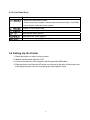
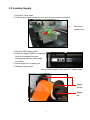
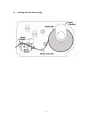
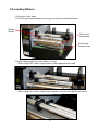
1
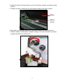
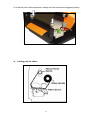
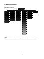
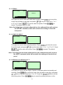
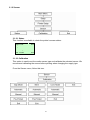
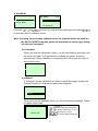
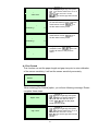
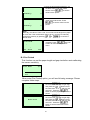
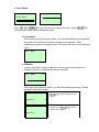
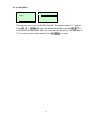
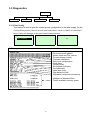
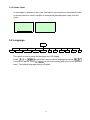
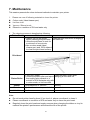
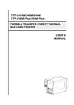
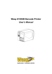
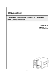
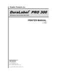
DuraLabel 9000 THERMAL TRANSFER / DIRECT THERMAL BAR CODE PRINTER Printer Manual Contents 1. Introduction................................................................................................ 1 1.1 Product Introduction ...............................................................................1 1.2 Compliances ............................................................................................1 2. Operations Overview ................................................................................. 3 2.1 Unpacking and Inspection ......................................................................3 2.2 Printer Overview ......................................................................................4 2.2.1 Front View ......................................................................................4 2.2.2 Interior View ...................................................................................5 2.2.3 Rear View........................................................................................6 2.3 Operator Controls ....................................................................................7 2.3.1 Front Panel Display .......................................................................7 2.3.2 LED Indicators ...............................................................................7 2.3.3 Front Panel Keys ...........................................................................8 2.4 Setting Up the Printer ..............................................................................8 2.5 Loading Supply ........................................................................................9 2.6 Loading Ribbon......................................................................................12 3. Menu Function ......................................................................................... 15 3.1 Setup Menu Overview............................................................................16 3.1.1 Printer Setup ................................................................................17 3.1.2 Sensor...........................................................................................23 3.1.3 Serial Comm.................................................................................31 3.1.4 Ethernet ........................................................................................34 3.2 File Manager ...........................................................................................37 3.2.1 File List .........................................................................................37 3.2.2 Avail. Memory...............................................................................38 3.2.3 Del. All Files..................................................................................38 3.3 Diagnostics ............................................................................................39 3.3.1 Print Config. .................................................................................39 3.3.2 Dump Mode ..................................................................................40 3.3.3 Rotate Cutter ................................................................................41 3.4 Language................................................................................................41 3.5 Service ....................................................................................................42 3.5.1 Initialization ..................................................................................42 1D bar code .................................................................................................. 44 2D bar code .................................................................................................. 44 i 6. Troubleshooting....................................................................................... 46 6.1 Common Problems ................................................................................46 7. Maintenance ............................................................................................. 49 ii 1. Introduction 1.1 Product Introduction Thank you for purchasing the DuraLabel® 9000 Industrial Sign and Label Printer. The DuraLabel 9000 provides thermal transfer printing (TTP) on continuous and die-cut supplies. It produces quality signs and labels with 300 DPI resolution and prints at speeds up to 3 ips. The DuraLabel 9000 includes a built-in high performance MONOTYPE IMAGING® True Type font engine and one CG Triumvirate Bold Condensed smooth font. With flexible firmware design, the True Type Font can be downloaded from a PC into the printer memory for printing labels. Besides the scalable font, it also provides a choice of five different sizes of alphanumeric bitmap font, OCR-A and OCR-B fonts. 1.2 Compliances CE Class A: EN55022:1998+A1:2000+A2:2003: EN55024:1998+A1:2001+A2:2003: EN 61000-4 SERIES REQULATIONS ETSI EN 301 489-17:V1.2.1(2002-08) FCC: CFR 47, Part 15/CISPR 22 3RD EDITION:1997, Class A (CAUTION: Danger of explosion if battery is incorrectly replaced. Replace only with the same or equivalent type recommended by the manufacturer. Dispose of used batteries according to the manufacturer instructions.) Federal Communication Commission (FCC) Interference Statement This equipment has been tested and found to comply with the limits for a Class B digital device, pursuant to Part 15 of the FCC Rules. These limits are designed to provide reasonable protection against harmful interference in a residential installation. This equipment generates, uses and can radiate radio frequency energy and, if not installed and used in accordance with the instructions, may cause harmful interference to radio communications. However, there is no guarantee that interference will not occur in a particular installation. If this equipment does cause harmful interference to radio or television reception, which can be determined by turning the equipment off and on, the user is encouraged to try to correct the interference by one of the following measures: - Reorient or relocate the receiving antenna. - Increase the separation between the equipment and receiver. - Connect the equipment into an outlet on a circuit different from that to which the receiver is connected. - Consult the dealer or an experienced radio/TV technician for help. This device complies with Part 15 of the FCC Rules. Operation is subject to the following two conditions: 1. This device may not cause harmful interference, and 2. This device must accept any interference received, including interference that may cause undesired operation. Information to User To assure continued compliance (example - use only shielded interface cables when connecting to computer or peripheral devices), any changes or modifications not expressly approved by the party responsible for compliance could void the user’s authority to operate this equipment. WARNING HAZARDOUS MOVING PARTS – KEEP FINGERS AND OTHER BODY PARTS AWAY CAUTION RISK OF EXPLOSION IF BATTERY IS REPLACED BY AN INCORRECT TYPE. DISPOSE OF USED BATTERIES ACCORDING TO THE INSTRUCTIONS. 2 2. Operations Overview 2.1 Unpacking and Inspection This printer has been specially packaged to withstand damage during shipping. Please carefully inspect the printer and its packaging upon receiving it. Please retain the packaging materials in case you need to return the printer. Check that all DuraLabel 9000 equipment and supplies are present and undamaged before proceeding. Equipment Checklist: • DuraLabel 9000 printer unit with built-in cutter • DuraLabel 9000 CD with printer driver, label templates and symbols • DuraLabel 9000 User’s Guide • DuraLabel 9000 QuickStart Guide • Power cord • USB cord • Supply guides (2) • Ribbon core • Ribbon guides with screws (2) If any parts are missing, please contact the Graphic Products customer service department at 1-800-788-5572. Please contact us for all your labeling needs. From standardized to custom labels, we’re ready to provide the labeling supplies you need. Call 1-800-788-5572 today to get your labeling problems solved. 3 2.2 Printer Overview 2.2.1 Front View 1 2 3 6 4 5 1. LED indicators 2. LCD display 3. Front panel buttons 4. Printed label opening 5. Cutter mechanism 6. Printer cover 4 2.2.2 Interior View 12 11 1 10 9 8 7 6 2 5 3 4 1. Ribbon Guides 2. Media Sensor (green) 3. Ribbon Sensor (black) 4. Print Head 5. Print Head Release Lever (green) 6. Adjustable Media Guides (white) 7. Media Guide Bar 8. Print Head Mechanism 9. Ribbon Spindle (back spindle) 10. Ribbon rewind spindle (front spindle) 11. Supply Bar 12. Supply Guides 13. Platen Roller (black) 13 5 2.2.3 Rear View 9 8 7 6 1 2 3 4 5 1. Fan-fold paper entrance chute 2. Parallel Port (Centronics Interface) 3. USB Interface 4. Serial Port (RS-232C Interface) 5. Power Jack Socket 6. Power Switch 7. PS/2 Interface 8. Ethernet Interface *9. SD Card Slot * Recommended SD card specification. SD V 1.0, V 1.1 SD V 2.0 (SDHC) 128MB 256MB 512MB 1GB 4GB class 6 -Supported DOS FAT file system. -Folders stored on the SD card should be in the 8.3 filename format. -Approved SD card manufacturer: SanDisk, Transcend. 6 2.3 Operator Controls 2.3.1 Front Panel Display LED indicators LCD display Front panel buttons 2.3.2 LED Indicators LED Status Indication Off Printer power off On Printer power on On Printer is ready Blinking Printer is paused Printer is downloading data Off Printer is ready On Carriage open OR cutter error Blinking No paper, paper jam OR "no ribbon” 7 2.3.3 Front Panel Keys Keys Function 1. Enter the initial menu screen 2. Once in the menu system, returns user to previous menu. If at initial menu screen, exits the menu system Pauses or resumes printing Advance one label Scroll up the menu options Scroll down the menu options Select the currently highlighted option 2.4 Setting Up the Printer 1. Place the printer on a flat, secure surface. 2. Make sure the power switch is OFF. 3. Connect the printer to the computer with the provided USB cable. 4. Plug the power cord into the AC power cord socket at the rear of the printer, and then plug the power cord into a properly grounded power outlet. 8 2.5 Loading Supply 1. Lift printer cover open. 2. Push the print head release lever to open the print head mechanism. Print head release lever 3. Remove ONE supply guide. 4. Adjust the supply guide to completely cover the numbered box that corresponds with the media width (in inches). 5. Place supply roll on supply bar. 6. Replace supply guide. Above: Inside Supply Guide set for 6" media/supply Supply guides Supply bar 9 6. Pull the leading edge of the label forward under the media guide bar, under the media sensor, and place the leading edge onto the platen roller and through the printed label opening. Media guide bar Media sensor Platen roller Adjustable media guides 7. Move the adjustable media guides to fit the supply width. 8. Close print head mechanism, making sure the print head release lever latches properly. Note: When using gap/black-mark media, calibrate printer by using the front display panel. 10 Loading path for label supply 11 2.6 Loading Ribbon 1. Lift printer cover open. 2. Push the print head release lever to pop-up the print head mechanism. Ribbon Guides Print Head Mechanism Print Head Release lever 3. Adjust ribbon guides to center ribbon on vinyl. - When using 8.66” ribbon, adjust ribbon guides against printer wall. - When using 4.33” ribbon, adjust ribbon guides to the line and tighten the screw. 12 4. Install the ribbon and empty ribbon core onto the ribbon spindle and ribbon rewind spindle. 5. Thread the ribbon underneath the print head and above the ribbon sensor. Ribbon Ribbon sensor 6. Apply ribbon onto empty ribbon core, keeping the ribbon flat and wrinkle-free. 7. Wind the ribbon rewind spindle clockwise roughly 3-5 times until ribbon is smooth, properly stretched and wrinkle-free. 13 8. Close the print head mechanism, making sure the latches are engaged properly. Loading path for ribbon 14 3. Menu Function Main Menu Overview Ma in Me nu Set up F ile M ana ger Diagno stics Lan guage Se rv ice ↓ ↓ ↓ ↓ ↓ P rint er S etup File List P rint Co nfig. E nglish Initialization ↓ ↓ ↓ ↓ Dum p Mod e Chinese(TC) M ilea ge I nfo . ↓ ↓ A vail. Me mo ry ↓ ↓ ↓ ↓ Serial Com m . Del. A ll F iles Ro tate Cut ter C hinese (SC) E xit ↓ ↓ ↓ ↓ *E therne t Exit E xit Ja pane se Sen sor ↓ ↓ E xit Germ an Exit ↓ Italian ↓ French ↓ Russian ↓ P olish ↓ S pan ish ↓ E xit Notice: * Ethernet function is available on the LCD display when Ethernet card is installed. 15 3.1 Setup Menu Overview Setup Printer Setup Sensor Serial Comm. Ethernet ↓ TSPL2 ↓ Status ↓ Baud Rate ↓ Status ↓ Z PL2 ↓ Calibration ↓ Parity ↓ Configure ↓ Exit ↓ Exit ↓ Data Bits ↓ Exit ↓ Stop Bit(s) ↓ Exit 16 Exit 3.1.1 Printer Setup Printer Setup TSPL2 Speed Density Direction ↓ 4 5 6 7 8 9 10 11 12 ↓ 0 1 2 3 4 5 6 7 8 9 10 11 12 13 14 15 ↓ 0 1 Print Mode Offset ↓ None Batch Mode Peeler Mode Cutter Mode Cutter Exit ↓ +000~- Shift X Shift Y ↓ +000~-000 +000~-000 17 Reference X Reference Y Code Page Country ↓ 000~999 ↓ 000~999 ↓ USA BRI GER FRE DAN ITA SPA SWE SWI 437 850 852 860 863 865 857 1252 1250 1253 1254 1251 1255 1256 1257 1258 8859-1 8859-2 8859-3 8859-4 8859-5 8859-6 8859-7 8859-8 8859-9 8859-10 8859-15 950 936 932 949 ↓ 001 002 003 031 032 033 034 036 038 039 041 042 044 045 046 047 048 049 055 061 351 358 Exit Exit SETUP FOR PRINTING WHEN NOT CONNECTED TO A COMPUTER: 3.1.1.1 Speed: Print Setup 1/12 Speed > Speed 2 Density Direction Use this option to set print speed. The available print speed is 2 or 3 ips. The default print speed is 2 ips. Press key to raise the print speed, and press key to decrease print speed. Press to accept, and press to cancel. Note: If printing from enclosed software/driver, the software/driver will send out the SPEED command, which will overwrite the setting set from the front panel. 3.1.1.2 Density: Print Setup 2/12 Speed Density > Density 8 Direction Use this option to setup printing darkness. The available setting is from 0 to 15, and the step is 1. Printer default density is 8. You may need to adjust your density based on selected media. Press or to increase/decrease the printing darkness. Press to enable the setting. Press to cancel. Note: If printing from enclosed software/driver, software/driver will send out DENSITY command, which overwrites the setting entered from the front panel. 3.1.1.3 Direction: Print Setup Speed 3/12 Direction Density 0 > Direction The direction setting value is either 1 or 0. Use this option to setup the printout direction. Printer default printout direction is DIRECTION 0. Press key to set the direction as 1, and 18 to set it as 0, and to enable the setting. Press to cancel. The following 2 figures are the printouts of DIRECTION 0 and 1 for your reference. DIRECTION 0 DIRECTION 1 Note: If printing from enclosed software/driver, the software/driver will send out the command, which overwrites the setting entered from the front panel. 3.1.1.4 Print Mode: (None/Batch Mode/Peeler Mode/Cutter Mode/Cutter Batch) Print Setup Density 4/12 Print Mode 2/6 > Batch Mode Direction Peeler Mode > Print Mode Cutter Mode This option is used to set the print mode. Printer default setting is Batch Mode. When entering this list, the print mode in the right side of " >" icon is the printer or to select the different print mode and current setting. Press press to enable the setting. Press to cancel. Printer Mode Description None Next label is aligned to the print head burn line location. (Tear Off Mode) Batch Mode Once image is printed completely, label gap/black-mark will be fed to the tear plate location for tear away. Peeler Mode Enable the label peel off mode. Cutter Mode Enable the label cutter mode. Cutter Batch Cut the label once at the end of the printing job. Note: If printing from enclosed software/driver, the software/driver will send out the command, which overwrites the setting set from the front panel. 19 3.1.1.5 Offset: Print Setup 5/12 Direction Offset Print Mode +000 > Offset This option is used to fine tune media stop location. Press cursor from left digit to right digit, and press to move the to set the value from “+” to “-” or “0” to “9”. Press to set the value into printer. Press cancel. The default value is +000. to Note: If printing from enclosed software/driver, the software/driver will send out the OFFSET command, which will overwrite the setting set from the front panel. 3.1.1.6 Shift X & Shift Y: Print Setup 7/12 Offset Shift Y Shift X +000 > Shift Y This option is used to fine tune print position. Press from left to right, and press to move the cursor to set the value from “+” to “-” or “0” to “9”. Press to set the value into printer. Press value is +000. to cancel. The default Note: If printing from enclosed software/driver, the software/driver will send out the SHIFT command, which will overwrite the setting set from the front panel. 3.1.1.6 Reference X & Reference Y: Print Setup Shift Y Reference X 9/12 Reference Y 000 > Reference Y This option is used to set the origin of printer coordinate system horizontally and vertically. Press to move the cursor from left digit to right digit, and press button to set the value from “0” to “9”. Press the button to set the value into printer. Press key to cancel the setting and return to the 20 previous menu. The default value is 000. Note: If printing from enclosed software/driver, the software/driver will send out the REFERENCE command, which will overwrite the setting entered from the front panel. 3.1.1.7 Code Page: Print Setup 10/12 Code Page Reference X > 850 Reference Y 852 11/41 860 > Code Page Use this option to set the code page of international character set. For more information about code page, call Graphic Products at 1-800-788-5572. When entering the code page list, the code page in the right side of ">" icon is the printer current setting. Press or the setting. Press to select the code page, and press to cancel. to enable Note: If printing from enclosed software/driver, the software/driver will send out the command, which overwrites the setting entered from the front panel. 7-bit 8-bit code page name International Character Set code page number International Character Set USA USA 437 United States BRI British 850 Multilingual GER German 852 Slavic FRE French 860 Portuguese DAN Danish 863 Canadian/French ITA Italian 865 Nordic SPA Spanish SWE Swedish SWI Swiss Windows Code Page (SBCS) Windows Code Page (DBCS) code page number International Character Set code page number International Character Set 1252 Latin 1 950 Traditional Chinese Big5 1250 Central Europe 936 Simplified Chinese GBK 1253 Greek 932 Japanese Shift-JIS 1254 Turkish 949 Korean 21 1251 Cyrillic 1255 Hebrew 1256 Arabic 1257 Baltic 1258 Vietnam ISO Code Page ISO Code Page code page name International Character Set code page number International Character Set 8859-1 Latin 1 8859-7 Greek 8859-2 Latin 2 8859-9 Turkish 8859-3 Latin 3 8859-10 Latin 6 8859-4 Baltic 8859-15 Latin 9 8859-5 Cyrillic 3.1.1.8 Country: Print Setup 11/12 Country 1/23 > 001 Reference Y 002 Code Page 003 > Country Use this option to set the country code for the LCD display. Press the and to select the country code, and press the button to set the value into printer. When enter this list, the country code in the right side of ">" icon is the printer current setting. Press key to cancel the setting and return to the previous menu. Code Country Code Country Code Country Code Country 001 USA 034 Spanish (Spain) 044 United Kingdom 055 Brazil 002 Canadian-French 036 Hungarian 045 Danish 061 English (International) 003 Spanish (Latin America) 038 Yugoslavian 046 Swedish 351 Portuguese 031 Dutch 039 Italian 047 Norwegian 358 Finnish 032 Belgian 041 Switzerland 048 Polish 033 French (France) 042 Slovak 049 German 22 3.1.2 Sensor 3.1.2.1 Status This function is available to check the printer’s sensor status. Paper Len. 812 Gap Size 24 Intensity 3 Ref. Level 512 3.1.2.2 Calibration This option is used to set the media sensor type and calibrate the selected sensor. We recommend calibrating the sensor before printing when changing the supply type. From the Sensor menu, follow this tree: 23 A. Gap Mode Calibration 1/4 > Gap Mode Gap Mode 1/4 > Automatic Bline Mode Manual Cont. Mode Pre-Printed or to move the cursor to the media type and press Press the to enter the sensor calibration mode. Note: If printing from enclosed software/driver, the software/driver will send out the GAP or BLINE command, which will overwrite the sensor type setting set from the front panel. A-1 Automatic When you enter the [Automatic] option, you will see following message, and the printer will feed 2 to 3 gap labels to calibrate the sensor sensitivity automatically. When calibration is completed, the LCD screen will return to the previous menu. Gap Mode Automatic A-2 Manual If “Automatic” sensor calibration is unable to adjust the supply, please use “Manual” function to calibrate the gap sensor manually. Gap Mode 2/4 Automatic > Manual Pre-Printed When you enter the [Manual] option, you will see following message. Please complete these steps: Paper Len. 00812 dot 1. Press to move the cursor from left digit to right digit, and press to set the value from “0” to “9” and the “dot/ mm/ inch”. Press to set the paper length into the printer. 24 2. Press to move the cursor from left digit to right digit, and press to set the value from “0” to “9” and the “dot/ mm/ inch”. Press to set the gap size into the printer. Gap Size 0024 dot Gap Mode Scan Backing Intensity Ref. Level x xxx 4. Then, put the label with liner under the media sensor. Press to set the value into the printer. Gap Mode Scan Paper Intensity Ref. Level x xxx Gap Mode Complete Intensity Ref. Level 3. Open the print head mechanism and put the label backing (liner) under the to media sensor. Press set the value into the printer. x 5. The gap sensor calibration is complete. Press ; the LCD screen will return to the previous menu. xxx A-3 Pre-Printed This function can set the paper length and gap size prior to auto-calibration of the sensor sensitivity. It will set the sensor sensitivity accurately. Gap Mode 3/4 Manual > Pre-Printed Exit When entering [Pre-Printed] option, you will see following message. Please complete these steps: Paper Len. 00812 dot Gap Size 0024 dot 1. Press to move the cursor from left digit to right digit, and press button to set the value from “0” to “9” and the “dot/ mm/ inch”. to set the paper Press length into the printer. 2. Press to move the cursor from left digit to right digit, and press to set the value from “0” to “9” and the “dot/ mm/ inch”. Press to set the gap size into the printer. 25 Gap Mode Pre-Printed 3. The printer will feed labels to calibrate the sensor sensitivity automatically. When calibration is completed, the LCD screen will return to the previous menu. 26 B. Bline Mode (also known as Black-Mark Mode, or labels with marks) Calibration 2/4 Bline Mode 1/4 Gap Mode > Automatic > Bline Mode Manual Cont. Mode Pre-Printed and to scroll the cursor to the sensor type. Press Press enter the black-mark sensor calibration mode. to B-1 Automatic When you enter the [Automatic] option, you will see following message and the printer will feed the black-mark label to calibrate the sensor sensitivity automatically. When calibration process is completed, the LCD screen will return to the previous menu. Bline Mode Automatic B-2 Manual In case “Automatic” sensor calibration cannot apply to the media, use “Manual” function to calibrate the bline sensor manually. Bline Mode 2/4 Automatic > Manual Pre-Printed When entering the [Manual] option, you will see following message. Please complete these steps: Paper Len. 00151 dot Bline Size 0024 dot 1. Press to move the cursor from left digit to right digit, and press to set the value from “0” to “9” and the “dot/ mm/ inch”. Press to set the paper length into the printer. 2. Press to move the cursor from left digit to right digit, and press to set the value from “0” to “9” and the “dot/ mm/ inch”. Press to set the bline size into the printer. 27 Bline Mode Scan Mark Intensity Ref. Level x xxx Bline Mode Scan Paper Intensity Ref. Level 3. Open the print head mechanism, put the black-mark under the media to set the sensor. Press value into the printer. x 4. Then, put the label without black-mark under the media sensor. Press to set the value into the printer. xxx Note: Normally, the value of “Ref. Level” for mark should be larger than paper for over 128. If the media sensor fails to do so, you have to manually or to reach the change the Intensity by pressing above value. Bline Mode Complete Intensity Ref. Level x 5. The bline sensor calibration is complete. Press ; the LCD screen will return to the previous menu. xxx B-3 Pre-Printed This function can set the paper length and gap size before auto-calibrating the sensor sensitivity. Bline Mode 3/4 Manual > Pre-Printed Exit When enter [Pre-Printed] option, you will see following message. Please complete these steps: Paper Len. 00812 dot Bline Size 0024 dot 1. Press the button to move the cursor from left digit to right digit, and press the button to set the value from “0” to “9” and the “dot/ mm/ inch”. Press the button to set the paper length into the printer. 2. Press the button to move the cursor from left digit to right digit, and press the button to set the value from “0” to “9” and the “dot/ mm/ inch”. Press the button to set the bline size into the printer. 28 Bline Mode Pre-Printed 3. Printer will feed labels to calibrate the sensor sensitivity automatically. When calibration is completed, the LCD screen will return to the previous menu. 29 C. Cont. Mode Calibration 3/4 Bline Mode Cont. Mode 1/3 > Automatic > Cont. Mode Manual Exit Exit or to scroll the cursor to the sensor type. Press Press enter the black-mark sensor calibration mode. to C-1 Automatic When entering the [Automatic] option, you will see following message and the printer will calibrate the sensor sensitivity automatically. When calibration process is completed, the LCD screen will return to the previous menu. Cont. Mode Automatic C-2 Manual In case “Automatic” sensor calibration cannot apply to the media, use “Manual” function to calibrate the sensor manually. Cont. Mode 2/3 Automatic > Manual Exit When you enter [Manual] option, you will see following message. Please complete these three steps: 1. Remove the label supply. Press to set the value into the printer. Cont. Mode Remove Label Intensity Ref. Level x xxx 2. Put the label supply under the media sensor. Press to set the value into the printer. Cont. Mode Scan Paper Intensity Ref. Level x xxx 30 3. The sensor calibration is complete. Press ; the LCD screen will return to the previous menu. Cont. Mode Complete Intensity Ref. Level x xxx 3.1.3 Serial Comm. Seria l Comm. Baud Ra te ↓ 1200 bps ↓ 2400 bps ↓ 4800 bps ↓ 9600 bps ↓ 19200 b ps ↓ 38400 b ps ↓ 57600 b ps ↓ 115200 bps ↓ Exit Parity ↓ None ↓ Odd ↓ Even ↓ Exit Data Bits ↓ 7 ↓ 8 ↓ Exit Stop Bit(s) ↓ 1 ↓ 2 ↓ Exit 31 Exit 3.1.3.1 Baud Rate Serial Comm. 1/5 > Baud Rate Baud Rate 4/9 > 9600 bps Parity 19200 bps Data Bits 38400 bps This option is used to set the RS-232 baud rate. The default setting is 9600 bps. Press or to select the different baud rate and press to set the value into the printer. When you enter this list, the baud rate value in the right side of ">" icon is the current setting in the printer. Press to cancel. 3.1.3.2 Parity Serial Comm. 2/5 Baud Rate Parity 1/4 > None > Parity Odd Data Bits Even This option is used to set the RS-232 parity. The default setting is “None”. Press or to select the different parity and press to set the value into the printer. When you enter this list, the parity in the right side of ">" is the printer current setting. Press to cancel. 3.1.3.3 Data Bits: Serial Comm. Baud Rate Parity > Data Bits 3/5 Data Bits 2/3 7 > 8 Exit This option is used to set the RS-232 Data Bits. The default setting is “8” data bits. Press or to select the different Data Bits and press to set the value into the printer. When you enter this list, the Data Bits in the right side of ">" icon is the printer current setting. Press 32 to cancel. 3.1.3.4 Stop Bit(s): Serial Comm. Parity Data Bits > Stop Bit(s) 4/5 Stop Bit(s) 1/3 > 1 2 Exit This option is used to set the RS-232 Stop Bits. The default setting is “1” stop bit. Press or to select the different Stop Bits and press to set the value into the printer. When you enter this list, the option in the right side of ">" icon is the printer current setting. Press 33 to cancel. 3.1.4 Ethernet Use this menu to configure internal Ethernet, check the printer’s Ethernet module status, and reset the Ethernet module. This function is available on the LCD display when an Ethernet card is installed. or Press the option. Press to select the different options and press to enter to cancel the setting and return to the previous menu. Ethernet Status ↓ IP Address ↓ MAC ↓ Exit Configure ↓ DHCP ↓ Static IP ↓ Exit Exit 3.1.4.1 Status: (IP Address / MAC) Use this menu to check the Ethernet setting status. 3.1.4.1.1 IP Address IP Address Ethernet > Status 1/3 Status 1/3 > IP Address 0.0.0.0 Subnet Mask Configure MAC 0.0.0.0 Exit Exit Gateway 0.0.0.0 34 The IP address information will be shown on the LCD display. Please press to return to the previous menu. or 3.1.4.1.2 MAC Ethernet 1/3 > Status Status 2/3 IP Address Configure MAC Address 001B82-FF0918 > MAC Exit Exit The MAC address information will be shown on the LCD display. Please press or to return to the previous menu. 3.1.4.2 Configure: (DHCP / Static IP) Use this menu to set the printer's DHCP and Static IP. 3.1.4.2.1 DHCP Ethernet 2/4 Status Configure 1/3 > DHCP > Configure Static IP Reset Exit Press or enter. Press to select the DHCP function and press to to cancel the setting and return to the previous menu. DHCP SELECT: MENU: Press Press YES NO the printer will set DHCP and restart to reset the setting. to return to the previous menu. 35 3.1.4.2.2 Static IP Use this menu to set the printer's IP address, subnet mask and gateway. Ethernet 2/3 Status Configure 2/3 DHCP > Configure > Static IP Exit Exit Press or enter the option. Press to select the different options and press to cancel. IP Address Subnet Mask Gateway 000.000.000.000 000.000.000.000 000.000.000.000 Press to to move the cursor from left to right digits and press the scroll the value from “0” to “9”. Press to move to the next setting. Static IP SELECT: MENU: Press YES NO . Printer will restart to reset the Ethernet module setting. Press key to cancel the setting. 36 to 3.2 File Manager This feature is used to check the printer’s available memory and file list. File Mana ger File List ↓ DRAM ↓ FLASH ↓ CARD ↓ Exit Avail. Memory Del. All Files ↓ DRAM ↓ FLASH ↓ CARD ↓ Exit Exit 3.2.1 File List Use this menu to show, delete and run (.BAS) the files saved in the printer DRAM/Flash/Card memory. To show the files: File Manager > File List 1/4 File List 2/4 > FLASH Avail. Memory CARD Del. All Files Exit > DEMO.TTF DEMO.BAS To delete the file, please follow the order to press FLASH File List FLASH File List . DEMO.TTF > DEMO.TTF 1.75 MB DEMO.BAS DOWN: Delete To run the file (.BAS), please follow the order to press FLASH File List DEMO.BAS DEMO.TTF > DEMO.BAS 406 Byte(S) DOWN: Delete SELECT: Run 37 . 3.2.2 Avail. Memory Use this menu to show available memory space. File Manager 2/4 File List Avail. Memory DRAM: > Avail. Memory 256 KB FALSH: Del. All Files 6656 KB CARD: 0 KB 3.2.3 Del. All Files Use this menu to delete all files. Press to delete all files in the device. Press to cancel deleting files and go back to previous menu. File Manager File List Avail. Memory > Del. All File 3/4 File List 1/4 Del. All Files > DRAM FALSH SELECT: CARD MENU: 38 YES NO 3.3 Diagnostics Diagnostics Print Config. Dump Mod e Rotate Cutter Exit 3.3.1 Print Config. This feature is used to print the current printer configuration to the label supply. On the configuration printout, there is a print head test pattern, which is useful for checking if there is any dot damage on the print head heater element. Diagnostics 1/4 Self Test ... > Print Config. Printing ... 1/1 Dump Mode Rotate Cutter Self-test printout Print head check pattern Model name and F/W version Printed mileage (meter) Firmware checksum Serial port configuration Code page Country code Print speed (inch/sec) Print darkness Label size (inch) Gap distance (inch) Gap/black-mark sensor sensitivity Numbers of download files Total & available memory space 39 3.3.2 Dump Mode Captures the data from the communications port and prints out the data received by the printer. In the dump mode, all characters will be printed in 2 columns as following. The left side characters are received from your system and right side data are the corresponding hexadecimal value of the characters. It allows users to verify and debug the program. Diagnostics 2/4 Printing ... Pritn Config. Dump Mode 1/1 > Dump Mode Rotate cutter Note: 1. Dump mode requires 4” wide paper width. 2. Turn off / on the power to resume printer for normal printing. 3. Press FEED button to back to the previous menu. DOWNLOA D "TEST2. DAT",5,CL S DOWNLO AD F,"TES T4.DAT",5 ,CLS DOW NLOAD "TE ST2.DAT", 5,CLS DO WNLOAD F, "TEST4.DA T",5,CLS DOWNLOAD "TEST2.D AT",5,CLS DOWNLOA D F,"TEST 4.DAT",5, CLS 0D 44 44 53 41 54 2C 4E 53 35 57 22 54 0A 20 41 0D 44 34 43 0A 20 41 0D 44 34 43 4C 54 2C 4E 54 22 44 22 54 0A 20 2E 4C 44 22 54 0A 20 2E 4C 4F 32 43 4C 45 2C 4F 54 22 44 46 44 53 4F 54 22 44 46 44 53 41 2E 4C 4F 53 35 57 45 2C 4F 2C 41 0D 57 45 2C 4F 2C 41 0D 44 44 53 41 54 2C 4E 53 35 57 22 54 0A 4E 53 35 57 22 54 0A 20 41 0D 44 34 43 4C 54 2C 4E 54 22 4C 54 2C 4E 54 22 44 22 54 0A 20 2E 4C 4F 32 43 4C 45 2C 4F 32 43 4C 45 2C 4F 54 22 44 46 44 53 41 2E 4C 4F 53 35 4I 2E 4C 4F 53 35 57 45 2C 4F 2C 41 0D 44 44 53 4I 54 2C ASCII Data Hexdecimal data related to left column of ASCII data 40 3.3.3 Rotate Cutter In case paper is jammed in the cutter, this feature can rotate the cutter blade forward or reverse direction, which is helpful to remove the jammed paper easily from the cutter. Diagnostics 3/4 Print Config. UP: Fwd. DOWN: Rev. Dump Mode > Rotate Cutter MENU: Exit 3.4 Language Language English Chinese (TC) Chinese (SC) Japanese G erman Italian French Russian Polish Spanish Exit This option is used to setup the language on LCD display. Press or to scroll the curser to desire language and press to select this option. Press to cancel the setting and return to the previous menu. The default language setting is English. 41 3.5 Service Service Initialization Mileage Info. Exit This feature is used to restore printer settings to defaults and display printer mileage information. 3.5.1 Initialization Service 1/3 Initialization Initializing ... > Initialization Mileage Info. SELECT Exit MENU YES NO The printer settings are restored to defaults as below once printer is initialized. Note : When printer initialization is done, please calibrate the gap or black-mark sensor before printing supplies with gap or black-mark sensor. Parameter Default setting Speed 2 IPS (50.8 mm/sec) Density 5.0 Label width 9"(219.5mm) Label length 15"(101.6mm) Sensor type Gap sensor Gap setting 0.12"(3.0mm) Print direction 0 Reference point 0,0(upper left corner) Offset 0 Print mode Batch mode Serial port settings 9600 bps, none parity, 8 data bits, 1 stop bit Code page 850 Country code 001 Clear flash memory No Shift X 0 Shift Y 0 Gap sensor sensitivity 3 (Will be reset. Need to re-calibrate the gap) Bline sensor sensitivity 2 (Will be reset. Need to re-calibrate the gap) Language English IP address DHCP 42 5. Printer Specifications Printer model DuraLabel 9000 Resolution 300 DPI Printing method Thermal Transfer & Direct Thermal Print speed Up to 3 ips Max. print width 215.9mm (8.5”), Center Bias Max. print length 1270 mm (50”) Enclosure Sheet metal structure with plastic cover 470mm(W) x 350 mm(H) x 550mm(D) 18.50” (W) x 13” (H) x 21.65” (D) Physical dimension Weight Ribbon 22kg (TBD) Ribbon width 300 M long, 1” core (ink outside) Support color ribbon 110mm ~ 254.0mm (4.33”~8.66”) Ribbon take up direction Same as DLP200/300 Label roll capacity 152.4 mm (6” ) OD Processor Memory Interface Power LCD display 32-bit ARM9 architecture micro processor, 200MHz Operation switch, button 8MB Flash memory 32MB SDRAM SD flash memory card slot for flash memory expansion Centronics (SPP mode) USB 2.0 client (full speed) RS232C Internal switching power supply Input: AC 115V/230V, 5A/3A, 50HZ/60HZ Graphic type, 122 x 32 pixel, with back light The number of printed label should be shown on LCD display LCD supported language: English Power switch at back side of printer 6 operation buttons (up, down, select, pause, feed, menu) 43 Sensors Internal font Code Page Transmissive gap sensor, easy to access when label is loaded Reflective black mark sensor (position adjustable) Transmissive ribbon end sensor (Ribbon end must be transparent) Head open sensor Print head heater element diagnostic 8 alpha-numeric bitmap fonts Monotype Imaging true type font engine Codepage 437 (English - US) Codepage 850 (Latin 1) Codepage 852 (Latin 2) Codepage 860 (Portuguese) Codepage 863 (French Canadian) Codepage 865 (Nordic) Codepage 857 (Turkish) Codepage 861 (Iceland) Codepage 1252 (Latin 1) Codepage 1250 (Latin 2) Codepage 1254 (Turkish) Latin-1 (ISO-8859-1: Western European) Latin-2 (ISO-8859-2: Central European) Latin-9 (ISO-8859-9: Turkish) 1D bar code Bar code Code 39, Code 93, Code128UCC, Code128 subsets A.B.C, Codabar, Interleave 2 of 5, EAN-8, EAN-13, EAN-128, UPC-A, UPC-E, EAN and UPC 2(5) digits add-on, MSI, PLESSEY, POSTNET, China POST, 2005 sunrise compliance barcode, RSS code 2D bar code PDF-417, Maxicode, DataMatrix, QR code Font & barcode rotation Printing ratio 0, 90, 180,270 degree Full black thickness can’t be greater than 12 dots in height Command set Media type TSPL-EZ Continuous, die-cut, Fan-fold, tag, notched, black mark, perforated, care label (width less than 3 inch) Media wound type Outside wound 44 Media width 101.6~223.5mm (4" ~ 9") Media thickness 0.025~0.254 mm (0.98mil~10 mil) Media core diameter 76.2 mm (3”) Label length 25.4~1270 mm (1.0”~50”) Label length (peel mode) N/A Label length (cutter mode) 25.4~1270 mm (1.0”~50”) Gap height Min. 2 mm Black mark height Min. 2 mm Black mark width Min. 8 mm (0.31”) Vertical: 1 mm max. Horizontal: 1 mm max. Printout bias o Operation: 5~40 C, 20~85% non-condensing Environment condition o Storage: -40~60 C, 5~90% non-condensing Safety regulation CE,FCC Class A Environmental concern Accessories Reliability Cutter Comply with RoHS, WEEE Software CD Quick start guide USB cord Power cord Platen: 50 km (service part) TPH warranty 1 million inch or 12 months whichever comes first Max. width 8.9” Cut thickness 10 mil (including label with liner) Media protection (option) Supply Guides Ribbon Guides with screws (2) Empty Ribbon supply core HF RFID 45 6. Troubleshooting 6.1 Common Problems The following guide lists the most common problems that may be encountered when operating the DuraLabel 9000. If the printer still does not function after all suggested solutions have been invoked, please contact Graphic Products Customer Service for assistance. Problem Possible Cause Recovery Procedure Power indicator does · The power cord is not properly connected. not illuminate · Plug the power cord in printer and outlet. · Switch the printer on. Carriage Open · The printer carriage is open. · Please close the print head mechanism. · Out of ribbon. · The ribbon is installed incorrectly. · Supply a new ribbon roll. · Please refer to the steps in user’s guide to · Out of label supply. · The label is installed incorrectly. · Gap/black-mark sensor is not · Supply a new label supply roll. · Please refer to the steps in user’s guide to No Ribbon No Paper calibrated. reinstall the ribbon. reinstall the label supply roll. · Calibrate the gap/black-mark sensor, when using gap/black-mark material. · Gap/black-mark sensor is not set · Verify media is loaded correctly and adjust properly. sensor to appropriate location. · Make sure label supply size is set · Calibrate the gap/black-mark sensor. properly. · Labels may be stuck inside the printer · Set label supply size correctly. mechanism. Paper Jam UP: · If the cutter module is installed, please press Fwd. Rev. · Cutter jam. · There is no cutter installed on the MENU: · Cutter PCB is damaged. DOWN: printer. Exit 46 UP or DOWN key to rotate the cutter up or down to move the blade back to the right position. · Remove the label. · Make sure the thickness of label is less than 0.254 mm (10mil) · Replace a cutter PCB. · Re-connect cable to interface. · If using serial cable, - Please replace the cable with pin to pin connected. - Check the baud rate setting. The default baud rate setting of printer is 9600,n,8,1. · If using the Ethernet cable, - Check if the Ethernet RJ-45 connector green LED is lit on. - Check if the Ethernet RJ-45 connector amber LED is blinking. - Check if the printer gets the IP address when using DHCP mode. - Check if the IP address is correct when using the static IP address. · Cable is not well connected to serial Wait a few seconds let the printer get the or USB interface or parallel port. Not Printing communication with the server then check · The serial port cable pin configuration the IP address setting again. is not pin to pin connected. · Change a new cable. · Ribbon and media are not compatible. · Verify the ribbon-inked side faces correct way. · Reload the ribbon again. · Clean the print head. · The print density setting is incorrect. · Print head’s harness connector is not well connected with print heat. Turn off the printer and plug the connector again. · Check if the stepping motor is plugging in the right connector. · Check your program if there is a command PRINT at the end of the file and it must have CRLF at the end of each command line. · Delete unused files in the FLASH/DRAM. · The max. numbers of file of DRAM is 256 files. · The max. user addressable memory space of Memory full DRAM is 2048 KB. · The space of FLASH/DRAM is full. · The max. numbers of file of FLASH is 256 ( FLASH / DRAM ) files. · The max. user addressable memory space of FLASH is 6656KB. · Use the supported capacity SD card. · Insert the SD card again. · The supported SD card spec. · SD card is damaged. - 128MB SD card is unable to · SD card doesn’t insert correctly. - 256MB - 512MB · Use the non-approved SD card use - 1GB manufacturer. - 4GB SDHC CLASS 6 · Approved SD card manufacturers; SanDisk, Transcend · Did not turn off power prior to plug in · Turn off printer power prior to plug in the PS/2 the PS/2 keyboard. keyboard . PS/2 port does not · PS/2 keyboard is damaged. · Plug the PS/2 keyboard again. · PS/2 keyboard doesn’t plug-in · Make sure the keyboard is fine. work correctly. · Make sure if there is any BAS file downloaded · There is no BAS file in the printer. into printer. 47 · Reload the supply. · Clean the print head. incorrectly · Dust or adhesive accumulation on the · Clean the platen roller. · Adjust the print density and print speed. print head. · Run printer self-test and check the print head Poor Print Quality · Print density is not set properly. test pattern if there is dot missing in the · Print head element is damaged. pattern. · Ribbon and media are incompatible. · Change proper ribbon or proper label media. · The print head pressure is not set · The release lever does not latch the print head properly. · Ribbon and media is loaded properly. LCD panel is dark and keys are not · The cable between main PCB and LCD panel is loose. · Check if the cable between main PCB and LCD is secured or not. working LCD panel is dark but · The printer initialization is the LEDs are light · Turn OFF and ON the printer again. · Initialize the printer. unsuccessful. · If the label is moving to the right side, please Label feeding is not · The media guide does not touch the stable (skew) when edge of the media. printing move the label guide to left. · If the label is moving to the left side, please move the label guide to right. · Label size is not specified properly. · Check if label size is setup correctly. · Sensor sensitivity is not set properly. · Calibrate the sensor by Auto Gap or Manual · The media sensor is covered with Gap options. printing · Clear the GAP/Black-mark sensor by blower. dust. · Set the correct label size. The left side printout · Wrong label size setup. · The parameter Shift X in LCD menu is · Press [MENU] [SELECT] x 3 [DOWN] x 5 Skip labels when position is incorrect [SELECT] to fine tune the parameter of Shift X. incorrect. Missing printing on the left or right side · Wrong label size setup. · Set the correct label size. of label RTC time is incorrect when reboot the · The battery has run down. · Check if there is a battery on the main board. · Power switch OFF and ON too fast. · Turn off the printer and wait all LEDs are dark, printer Power and Error LEDs are blinking and turn on the printer again. fast Wrinkle Problem Line on the blank label Irregular printing · Print head pressure is incorrect. · Ribbon installation is incorrect. · Media installation is incorrect. · Print density is incorrect. · Media feeding is incorrect. · Make sure the adjustable label guides touch the edge of the media. · Make sure label, paper core and ribbon are set at the appropriate settings. Adjust ribbon guides and/or label guides as necessary. · Manually remove wrinkles with hands. · The print head is dirty. · The platen roller is dirty. · Clean the print head. · Clean the platen roller. · The printer is in Hex Dump mode. · The RS-232 setting is incorrect. · Turn off and on the printer to skip the dump 48 mode. · Re-set the Rs-232 setting. 7. Maintenance This session presents the clean tools and methods to maintain your printer. 1. Please use one of following materials to clean the printer. Cotton swab (Head cleaner pen) Lint-free cloth Vacuum / Blower brush Ethanol or a solution of IPA and water only 2. The cleaning process is described as following Printer Part Method Interval 1. Always turn off the printer Clean the print head when changing a before cleaning the print head. new label roll 2. Allow the print head to cool for a minimum of one minute. 3.Use a cotton swab (Head cleaner pen) and 100% ethanol to clean the print head surface. Print head Exterior 1. Turn OFF power. Clean the platen roller when 2. Rotate the platen roller and wipe it changing a new label roll thoroughly using ethanol or a solution of IPA and water only with a cotton swab, or lint-free cloth. Compressed air or vacuum Monthly Wipe it with water-dampened cloth As needed Interior Brush or vacuum Platen Roller Sensor As needed Note: Do not touch printer head by hand. If you touch it, please use ethanol to clean it. Please use ethanol or a solution of IPA and water only to clean the print head. Regularly clean the print head and supply sensors when changing the ribbon or vinyl to maintain the printer’s performance and extend the life of the printer. 49 50