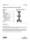
1
Multipath Ultrasonic Gas Flowmeter MPU Series B User Manual Procedure Manual USM-0000020565 / Rev. 00G / FL / nb / September 2011 Meter with optional cable protection cover The Most Trusted Name In Measurement MNKS001 0.3 (9/11) User Manual User Manual MPU Series B Procedure History Revision Date Editor ECN Status Rev. 01/ A 09.11.2006 xxx 50000058026 released Took over from KOS SAP System Description Rev. 00C November 2007 NB 20092 released Approval Rev. 00D January 2009 ThK 20512 releases Change cover and footer Rev. 00E February 2009 NB 20513 releases MPU 800 update Rev. 00F July 2010 NB 21064 releases Front page update Rev. 00G September 2011 JP 21510 releases Temperature drop /depressurization Important All information and technical specifications in this documentation have been carefully checked and compiled by the author. However, we cannot completely exclude the possibility of errors. Smith Meter GmbH is always grateful to be informed of any errors. Page 2 of 123 USM-0000020565 Rev. 00G MNKS001 0.3 (9/11) TABLE OF CONTENTS 1 INTRODUCTION ............................................................................................................ 9 1.1 Contact Address if Assistance is Required ............................................. 9 1.2 Copyright .................................................................................................... 9 1.3 Trademarks ................................................................................................. 9 1.4 Manual Structure and Use ....................................................................... 10 1.4.1 References ............................................................................................................ 10 1.4.2 Abbreviations ....................................................................................................... 10 2 MAIN DATA FOR OPERATION AND MAINTENANCE ...................................... 11 2.1 Purpose of Equipment ............................................................................. 11 2.2 Health, Environment and Safety ............................................................. 11 2.2.1 Warnings .............................................................................................................. 11 2.2.2 Hints for installation in hazardous area ................................................................ 12 2.2.3 EC-Type-Examination Certificate........................................................................ 13 2.2.4 Temperature drop and depressurization ............................................................... 13 2.3 Capacity and Performance ...................................................................... 15 2.3.1 Guarantee ............................................................................................................. 15 2.3.2 Durability Data ..................................................................................................... 15 2.3.3 Instrument Data Specifications ............................................................................ 16 2.3.4 Model Code .......................................................................................................... 19 2.3.5 Cable Specifications ............................................................................................. 21 2.3.5.1 Main power, 230/240 , 115/120 VAC .......................................................... 22 2.3.5.2 Main power, 24 VDC ................................................................................... 22 2.3.5.3 Instrument Earth cable (IE) .......................................................................... 22 2.3.5.4 Ethernet, twisted pair (10Base-T) ................................................................ 22 2.3.5.5 Ethernet, fiber Link (10Base-FL) ................................................................. 23 2.3.5.6 Serial RS-232 ............................................................................................... 23 2.3.5.7 Serial RS-485 (2-wire and 4 wire) ............................................................... 23 2.3.5.8 Analog Input/Output .................................................................................... 23 2.3.5.9 Digital Input/Output ..................................................................................... 24 2.3.5.10 Pulse Output ............................................................................................. 24 2.3.6 Software Interfaces ............................................................................................... 24 2.3.7 Main Connections and Connected Systems ......................................................... 25 2.3.8 Weight and Outline Dimensions .......................................................................... 26 3 TECHNICAL DESCRIPTION ..................................................................................... 28 3.1 Product Overview ..................................................................................... 28 3.2 The MPU features ..................................................................................... 29 3.3 Instrument Design .................................................................................... 29 3.4 Mechanical Design ................................................................................... 29 3.5 Principle of Operation .............................................................................. 29 3.6 Measurement Principle ............................................................................ 34 3.6.1 Transit Time Measurement .................................................................................. 34 3.6.2 Travel Time Corrections ...................................................................................... 35 3.6.3 Calculate Average Gas Flow Velocity ................................................................. 35 USM-0000020565 Rev. 00G MNKS001 0.3 (9/11) Page 3 of 123 User Manual User Manual MPU Series B Procedure 4 RECEPTION AND INSTALLATION ......................................................................... 38 4.1 Reception Procedure ............................................................................... 38 4.1.1 Unpacking and Inspection .................................................................................... 38 4.1.2 Identification and Marking ................................................................................... 39 4.2 Installation Procedure .............................................................................. 44 4.2.1 Pre-Installation Procedures .................................................................................. 44 4.2.1.1 Installation Requirements ............................................................................. 44 4.2.1.2 Mechanical Inspection.................................................................................. 44 4.2.2 Installation of the Spool Piece .............................................................................. 45 4.2.2.1 Equipment and Tools required ..................................................................... 45 4.2.3 Cabling Overview ................................................................................................ 45 4.2.3.1 Power supply ................................................................................................ 48 4.2.3.2 Transducer wiring ........................................................................................ 49 4.2.3.3 Communication ............................................................................................ 50 4.2.4 Installation of Cables ............................................................................................ 51 4.2.4.1 ATEX Requirements (European Versions) .................................................. 51 4.2.4.2 Cable Installation Check List ....................................................................... 52 4.2.4.3 Loop Check .................................................................................................. 53 4.2.4.4 Power Cables ................................................................................................ 54 4.2.4.5 Communication and Analogue I/O Cables................................................... 54 4.2.4.6 Digital I/O Cables......................................................................................... 55 4.2.4.7 Fibre Optical Cables ..................................................................................... 55 5 OPERATION .................................................................................................................. 57 5.1 Basic Information to Operator................................................................. 57 5.1.1 Operating Area and Manoeuvring Gear ............................................................... 57 5.1.2 Skill Requirement ................................................................................................. 57 5.1.3 Elements of Risk .................................................................................................. 57 5.2 Pre-operation ............................................................................................ 57 5.2.1 Purpose ................................................................................................................. 57 5.2.2 Equipment Required ............................................................................................. 58 5.2.3 PC Configurations ................................................................................................ 58 5.2.4 Check list prior to power on ................................................................................. 58 5.2.5 Start flow measurement ........................................................................................ 59 5.3 Operating Procedures.............................................................................. 59 5.3.1 Install and start the WinScreen program .............................................................. 59 5.3.1.1 Change Password ......................................................................................... 60 5.3.1.2 Change Security Level ................................................................................. 61 5.3.1.3 Connecting to the Ultrasonic Meter ............................................................. 61 5.3.2 Establish communication with Ethernet link ....................................................... 63 5.3.3 Establish communication with serial link ............................................................ 64 5.3.4 RS-232 Serial Link Configuration ....................................................................... 66 5.3.4.1 RS-232 Serial Link with WinScreen on PC ................................................. 66 5.3.4.2 RS-485 4-wire Full Duplex Configuration................................................... 67 5.3.4.3 RS-485 Full Duplex Serial Link with WinScreen on PC ............................. 67 5.3.4.4 RS-485 2-wire Half Duplex Configuration .................................................. 68 5.3.4.5 RS-485 Half Duplex Serial Link with WinScreen on PC ............................ 68 5.3.4.6 Run WinScreen against PC Simulator ......................................................... 69 Page 4 of 123 USM-0000020565 Rev. 00G MNKS001 0.3 (9/11) User Manual User Manual MPU Series B Procedure 5.3.4.7 Trouble Shooting – Ethernet ........................................................................ 69 5.3.5 Operating the MPU WinScreen program ............................................................. 69 5.3.5.1 Menu Overview ............................................................................................ 69 5.3.5.2 Measured Values .......................................................................................... 71 5.3.6 Alarms and Self-diagnostics................................................................................. 73 5.3.6.1 Active Alarm Log......................................................................................... 73 5.3.6.2 Historical Alarm Log ................................................................................... 73 5.3.6.3 Checksum error alarm .................................................................................. 73 5.3.6.4 Internal calculation failure alarm ................................................................. 73 5.3.6.5 Velocity of sound deviation alarm ............................................................... 73 5.3.6.6 Flow speed deviation alarm.......................................................................... 74 5.3.6.7 High flow alarm ........................................................................................... 74 5.3.6.8 Gain deviation alarm .................................................................................... 74 5.3.6.9 Transducer failure alarm .............................................................................. 74 5.3.6.10 Hardware error alarm ............................................................................... 74 5.3.7 Transducer failure – correction algorithms .......................................................... 75 5.3.7.1 Reduced accuracy with respect to transducer failure ................................... 75 5.3.7.2 Dynamic flow profile monitoring ................................................................ 75 5.3.7.3 Profile learning ............................................................................................. 76 5.3.7.4 Flow measurement with profile check ......................................................... 76 6 MAINTENANCE ........................................................................................................... 79 6.1 Periodical Inspection and Maintenance ................................................. 79 6.1.1 Inspection every 3rd month ................................................................................... 79 6.1.2 Replacement of O-rings and Backup-rings .......................................................... 80 6.2 Troubleshooting and Replacement of Parts .......................................... 81 6.2.1 Self diagnostics features ....................................................................................... 81 6.2.1.1 Alarm status word ........................................................................................ 82 6.2.1.2 Active alarm log ........................................................................................... 83 6.2.1.3 Historical alarm log ...................................................................................... 83 6.2.1.4 Event log ...................................................................................................... 84 6.2.1.5 Operator change log ..................................................................................... 84 6.2.1.6 All log entries ............................................................................................... 85 6.2.2 Malfunction or errors during operation ................................................................ 85 6.2.3 Troubleshooting diagrams .................................................................................... 86 6.2.4 LEDs Overview .................................................................................................... 88 6.2.5 Fuses Locations .................................................................................................... 89 6.2.6 Replacement of Electronics Board ....................................................................... 89 6.2.6.1 Replacement of UAFE (analog front end) board ......................................... 90 6.2.6.2 Replacement of UDSP (digital signal processing) board ............................. 90 6.2.6.3 Replacing complete electronics (UAFE and UDSP board) ......................... 90 6.2.7 Software configuration ......................................................................................... 90 6.2.8 Replacement of Transducers ................................................................................ 91 6.2.9 Database Configuration ........................................................................................ 91 6.2.10 Change parameters ........................................................................................... 93 6.2.11 Database Report ............................................................................................... 94 6.2.11.1 Print Database Report............................................................................... 95 6.2.11.2 Save Database Report............................................................................... 95 6.2.11.3 Open Database Report .............................................................................. 95 USM-0000020565 Rev. 00G MNKS001 0.3 (9/11) Page 5 of 123 User Manual User Manual MPU Series B Procedure 6.3 Storage and Preservation of the MPU and Spare Parts ........................ 96 6.3.1 SHORT term storage - up to one month .............................................................. 96 6.3.2 LONG term storage - more than one month ........................................................ 96 6.3.3 Preservation .......................................................................................................... 96 6.4 Instructions for Packing and Transport ................................................. 97 7 SPARE PARTS ............................................................................................................... 98 8 HANDLING AND TRANSPORTATION ................................................................. 102 8.1 9 Spool Piece ............................................................................................. 102 APPENDIX ................................................................................................................... 104 9.1 Wiring Examples .................................................................................... 104 9.1.1 Power Supply – AC ............................................................................................ 104 9.1.2 Power Supply – DC ............................................................................................ 104 9.1.3 Ethernet – twisted pair........................................................................................ 105 9.1.3.1 Straight through .......................................................................................... 105 9.1.3.2 Cross-over cable ......................................................................................... 105 9.1.4 Ethernet – Optical fibre ...................................................................................... 107 9.1.5 Serial communication – RS-232 ........................................................................ 109 9.1.5.1 Example of RS-232 communication with PC (WinScreen) ....................... 109 9.1.6 Serial Communication – RS 485 Full Duplex .................................................... 110 9.1.6.1 Example based on Westermo MD 44 converter and a PC ......................... 110 9.1.7 Serial Communication – RS485 Half Duplex .................................................... 111 9.1.7.1 Example based on Westermo MD 44 converter and a PC ......................... 112 9.1.7.2 Example based on OMNI flow computer .................................................. 113 9.1.8 Pulse Output ....................................................................................................... 113 9.1.9 Digital Output ..................................................................................................... 115 9.1.10 Digital Input ................................................................................................... 115 9.1.11 Analog Output ................................................................................................ 116 9.1.11.1 Analog Output 4-20 mA ......................................................................... 116 9.1.11.2 Analog Ouput 1-5 V ............................................................................... 116 9.1.12 Analog Input ................................................................................................... 117 9.1.12.1 Analog Input 4-20 mA ........................................................................... 117 9.1.12.2 Analog Input 1-5 VDC ........................................................................... 117 9.2 External Wiring Connections ................................................................ 118 9.3 Declaration of Conformity ..................................................................... 119 Page 6 of 123 USM-0000020565 Rev. 00G MNKS001 0.3 (9/11) User Manual User Manual MPU Series B Procedure Figures Figure Figure Figure Figure Figure Figure Figure Figure Figure Figure Figure Figure Figure Figure Figure Figure Figure Figure Figure Figure Figure Figure Figure Figure Figure Figure Figure Figure Figure Figure Figure Figure Figure Figure Figure Figure Figure Figure Figure Figure Figure Figure Figure Figure Figure Figure Figure Figure Figure Figure Figure Figure 1 – Flame Paths .............................................................................................................. 14 2 – Main Connections ...................................................................................................... 25 3 – MPU Face to face dimension ....................................................................................... 26 4 – MPU Product Overview ............................................................................................... 28 5 – MPU 1200 path configuration ...................................................................................... 31 6 – MPU 800 path configuration........................................................................................ 31 7 – MPU 600 path configuration........................................................................................ 32 8 – MPU 200 path configuration........................................................................................ 32 9 – Top View of path, travel times .................................................................................... 34 10 – Front view of pipe, showing internal positions of the paths .......................................... 35 11 – Top View of pipe, with axial and transverse flow indicated........................................... 36 12 – Front view of pipe, showing flow regimes................................................................... 36 13 – MPU in Transportation Box ....................................................................................... 38 14 – Transducer and Electronic marking (MPU 1200) .......................................................... 40 15 – Transducer and Electronic marking (4” until 10” MPU 800) .......................................... 41 16 – Transducer and Electronic marking (at 12” MPU 800) .................................................. 42 17 – Transducer and Electronic marking (MPU 600) ........................................................... 43 18 – MPU Electronics ....................................................................................................... 46 19 – MPU Electronics overview ......................................................................................... 47 20 – Transducer wiring .................................................................................................... 49 21 – UDSP board terminals .............................................................................................. 50 22 – Example of EEx d Cable Gland Connection (European Model) ....................................... 52 23 – Serial Port Hardware Configuration ............................................................................ 64 24 – RS-232 Serial Communication Wiring ......................................................................... 66 25 – RS-485 Full Duplex Serial Communication Wiring ........................................................ 67 26 – RS-485 Half Duplex Serial Communication Wiring ....................................................... 68 27 – No output from the MPU (Communication failure) ....................................................... 86 28 – Suspicious Flow Measurement ................................................................................... 87 29 – Visible LEDs on the UDSP board ................................................................................ 88 30 – Electronics board locations........................................................................................ 89 31 – MPU in Transportation Box ....................................................................................... 97 32 - Electronic Box .......................................................................................................... 98 33 – Transducer .............................................................................................................100 34 – Wiring Power Supply AC ..........................................................................................104 35 – Wiring Power Supply DC ..........................................................................................104 36 – Ethernet twisted pair - straight through ....................................................................105 37 – Ethernet twisted pair - cross-over cable ....................................................................105 38 – Pin configuration in RJ45 plug ..................................................................................106 39 – Wiring Ethernet Optical Fibre ...................................................................................107 40 – EtherTRAK Industrial Ethernet Switch .......................................................................107 41 – CN14 jumper setting for RS232 ................................................................................109 42 – RS-232 serial communication with PC .......................................................................109 43 – CN14 jumper settings for RS485 full duplex ...............................................................110 44 – DIP switch settings for Westermo MD-44, RS485 full duplex .......................................110 45 – Westermo MPU Wiring Diagram, RS485 full duplex ....................................................111 46 – CN14 jumper settings for RS485 - half duplex ...........................................................111 47 – DIP switch settings for Westermo MD-44, RS485 half duplex ......................................112 48 – Westermo MPU Wiring Diagram, RS485 half duplex ...................................................112 49 – Pulse Wiring - Example 1 .........................................................................................114 50 – Pulse Wiring - Example 2 .........................................................................................114 51 – Wiring Diagram - Digital Output ...............................................................................115 52 – Wiring Diagram - Digital Input .................................................................................115 USM-0000020565 Rev. 00G MNKS001 0.3 (9/11) Page 7 of 123 User Manual User Manual MPU Series B Procedure Figure Figure Figure Figure Figure Table Table Table Table Table Table Table Table Table Table Table Table 53 54 55 56 57 – – – – – Wiring Analog Output - 4-20 mA ..............................................................................116 Wiring Analog Output - 1-5 V ...................................................................................116 Analog Input - 4-20 mA ...........................................................................................117 Analog Input - 1-5 VDC ...........................................................................................117 MPU Series B External Wiring Diagram ......................................................................118 Tables 1 – Flow rate versus dimension ......................................................................................... 20 2 - Typical MPU Dimension A (Inches) ................................................................................ 26 3 – Typical MPU Dimension A (mm) ................................................................................... 26 4 – MPU Overall Weights (lbs) (approx.) ............................................................................ 27 5 – MPU Overall Weights (kgs) (approx.) ............................................................................ 27 6 – Transducers marking................................................................................................... 39 7 – Serial Port Software Configuration ................................................................................ 64 8 – Serial Port Communication Parameter Settings .............................................................. 65 9 – Troubleshooting overview ............................................................................................ 85 10 – Colour Code Ethernet Straight Through Cable .............................................................106 11 – Colour Code Ethernet Cross-over Cable ......................................................................106 12 – Sixnet EtherTRAK Fiber Converter LED descriptions.....................................................108 Page 8 of 123 USM-0000020565 Rev. 00G MNKS001 0.3 (9/11) MPU Series B Ultrasonic Gas Flow Meter 1 INTRODUCTION INTRODUCTION This document describes the technical data information, storage, transport and handling, installation, operation and maintenance of the MPU Ultrasonic Gas Flow Meter. There are currently four versions available, MPU 1200, MPU 800, MPU 600 and MPU 200. The difference between them is the number of paths. All other parts are identical. The MPU 1200 has 6 paths (12 transducers), MPU 800 has 4 paths (8 transducers), MPU 600 has 3 paths (6 transducers) and the MPU 200 has 1 path (2 transducers). All version use identical electronics with the appropriate number of transducers connected. The MPU 600 is a lower cost version of the MPU 1200 and MPU 800 with slightly lower measurement performance. The MPU 200 is made for applications with lower accuracy requirements. 1.1 Contact Address if Assistance is Required Publisher Customer Support Contact Address: FMC Technologies Smith Meter GmbH Regentstrasse 1 P.O. Box 1012 25470 Ellerbek Germany FMC Technologies (Service Department) Regentstrasse 1 P.O. Box 1012 25474 Ellerbek Germany Phone No.: (49) 41 01 304 - 0 (49) 41 01 304 - 0 Fax No.: (49) 41 01 304 - 133 (49) 41 01 304 - 133 E-Mail: [email protected] [email protected] Internet: www.fmctechnologies.com/measurementsolutions 1.2 Copyright All technical information contained in this manual, including any drawings and technical specifications, shall remain the property of FMC Technologies and may not be used (other than for the operation of this product), copied, multiplied, passed on or communicated to a third party without prior written permission of FMC Technologies. © 2003 FMC Technologies 1.3 Trademarks Products listed are trademarks of their respective manufacturers. Company names listed are trade names of their respective companies. USM-0000020565 Rev. 00G MNKS001 0.3 (9/11) Page 9 of 123 User Manual 1.4 Manual Structure and Use 1.4.1 References The following documents are referred to within this manual: PRD-0000022520 MPU Transducer Replacement Procedure DOK-509 MPU Transducer Replacement Procedure (V6- short Transducer) using Retraction Tool PRD-0000022543 External Data Communication MPU Series B 1.4.2 Abbreviations Abbreviation Description AGA American Gas Association AI Analog Input AO Analog Output D Diameters DI Digital Input DO Digital Output I/O Input / Output Kb Kilo byte Mb Mega byte MPU Multi-Path Ultrasonic PC Personal Computer PE Protective Earth SW Software TRT Transducer Retraction Tool UACF Ultrasonic Alternate Current Filter UAFE Ultrasonic Analog Front End UDSP Ultrasonic Digital Signal Processor VOS Velocity Of Sound Page 10 of 123 USM-0000020565 Rev. 00G MNKS001 0.3 (9/11) MPU Series B Ultrasonic Gas Flow Meter 2 MAIN DATA FOR OPERATION AND MAINTENANCE MAIN DATA FOR OPERATION AND MAINTENANCE The purpose of this chapter is to give the user, both the single operator and the customer’s organization, basic data to ease the planning regarding location, installation, operation and maintenance of the delivered product. 2.1 Purpose of Equipment The MPU series of ultrasonic flow meters are non-intrusive and transducers are flush mounted to the internal meter body to provide for undisturbed and accurate measurement of gas flow. They are suitable for a wide range of applications in fiscal metering of dry, high pressure, and non-condensing gases, such as: Custody transfer of gas onshore and offshore Pipeline node bi-directional measurements Gas terminals Gas mixing stations Gas power plants Pipeline junctions Compressor stations The MPU 1200 and MPU 800 have fiscal accuracy with 10D straight upstream pipe, and 5D downstream straight pipe. The MPU 600 has fiscal accuracy with a well developed flow profile, hence long (>20D) upstream straight pipe or in combination with a flow conditioner. The MPU 200 can not be guaranteed for fiscal accuracy 2.2 Health, Environment and Safety Precautions must be taken during operation of this equipment to prevent human injury or health problems. To uphold the human and equipment safety during use and operation of the MPU, the equipment is CE-certified. Refer to Section 2.3.3. 2.2.1 Warnings If using a crane when lifting the MPU, the certified lifting slings must be wrapped around the meter, or use lifting lugs if available. Lifting and handling must always be performed in accordance with THI-0000020502. At offshore installations, it is very important to secure the meter during crane handling due to motion on the platform or vessel resulting in pendulum motion of the load. Do not fasten any lifting slings in the electronic connection box or its bracket. USM-0000020565 Rev. 00G MNKS001 0.3 (9/11) Page 11 of 123 User Manual 2.2.2 Hints for installation in hazardous area All assembly groups which are marked with the sign are explosion proof, electrical equipment. This equipment is tested for safety and approved by a notified body. ** * Any modifications made by unauthorized people, independent of mechanical or electrical matter, are forbidden Danger of ** * explosion In case of a malfunction of the electronic board fitted in the flameproof housing only the complete board has to be replaced. Test and repair of the board is only possible in the factory. The installation and replacement of the board is the task of skilled personnel. General hints: The electrical installation has to be compliant with EN 60079-14 and the ordinary electric installation rules. To prevent ignition of hazardous atmospheres and to prevent electrical shock, disconnect from supply circuits before opening. Protect the device against unintended power on. Before bringing the device into operation make sure that it is tightly closed. The flameproof housing contains one or more of the following threaded entries: ½” NPT. All cable entries, stopping boxes or plugs shall be certified according to the requirements in EN 50018 or IEC 60079-1. The flameproof housing contains an internal battery-powered circuit. Do not open the housing unless an area is known to be non-hazardous. To reduce the risk of ignition of hazardous atmospheres, conduit runs must have a sealing fitting connected within 45 cm of the enclosure. Before the first power up after installation check that the connected voltage is conform to power rating on the name plate. Not used cable entries have to be closed with certified plugs. The wiring has to be made according to the wiring diagrams which are part of this manual. Modification of the internal construction of the flameproof and adding additional parts to the electronic are not allowed Special precaution must be made when bringing the supplied Laptop / PC into hazardous area. Provide for work permit before bringing the Laptop / PC into restricted area, according the site regulations. A gas detector must be in operation continuously while the Laptop / PC is present in the restricted area. This applies also while it is switched off. The ex-relevant data could be found in chapter 2.3.3. Page 12 of 123 USM-0000020565 Rev. 00G MNKS001 0.3 (9/11) MPU Series B Ultrasonic Gas Flow Meter MAIN DATA FOR OPERATION AND MAINTENANCE The MPU is manufactured in the following versions: IEC/ ATEX - European certification 2.2.3 EC-Type-Examination Certificate EC-Type-examination Certificate No. Protection Method PTB 07 ATEX 1018 Ex d IIC T5 and T4 Nemko 05 ATEX 1244 EEx d IIB T5 Conformance to the EU guideline 89/336/EWG and the ATEX regulation 94/9/EC 2.2.4 Temperature drop and depressurization Please be aware that rapid temperature changes may damage the ultrasonic transducers and should be avoided. If the meters are subjected to a temperature change of more than 5 degrees Celsius or 9 degrees Fahrenheit per 5 minutes transducers may be damaged and may have to be replaced. This can also occur under rapid pressure changes like emergency depressurization, therefore, the maximum rate of depressurization is 10 bars per 5 minutes. USM-0000020565 Rev. 00G MNKS001 0.3 (9/11) Page 13 of 123 User Manual CAUTION: Special attention is required to avoid damage to flame paths. See Figure 1 below. If the flame paths are damaged, the parts must be replaced and not repaired. Figure 1 – Flame Paths Page 14 of 123 USM-0000020565 Rev. 00G MNKS001 0.3 (9/11) MPU Series B Ultrasonic Gas Flow Meter MAIN DATA FOR OPERATION AND MAINTENANCE 2.3 Capacity and Performance 2.3.1 Guarantee FMC Technologies, Smith Meter GmbH and its subsidiaries assume no responsibility for any errors that may appear in this publication, or for damages arising from the information in it. No information in this publication should be regarded as a warranty made by FMC Technologies, Smith Meter GmbH. The information in this publication may be updated without notice. The guarantee terms are stipulated in the delivery conditions. The guarantee on the equipment expires if: Equipment is damaged during transport, handling, storage or installation where instructions are not followed or due to carelessness. Service, operation and maintenance are not carried out strictly in accordance with the instructions described in section 7. Repairs are not carried out by our personnel, or if they are carried out by your staff without our prior written permission and strictly in accordance with the instructions. Changes are made to the equipment without our prior written permission. Original MPU parts are not used. Equipment is used improperly, incorrectly, carelessly or not in line with its nature and/or purpose. 2.3.2 Durability Data The MPU has the following durability data: Mean-time-between-failure (estimated figures): 150 000 hours Mean-time-to-repair: < 2 hours Equipment lifetime: 25 years USM-0000020565 Rev. 00G MNKS001 0.3 (9/11) Page 15 of 123 User Manual 2.3.3 Instrument Data Specifications Applications Dry high pressure gases, non-condensing Operating Pressure range 1-275 bar/ 1 to 3,990 psig Wider pressure range on request. Operating flow temperature -20 to 70 C/ -4 to 158 F Operating Ambient temperature -25 to 60 C/ -13 to 140 F Storage temperature -20 to 70 C/ -4 to 158 F Humidity Up to 95%, non-condensing Flow Range (typical) MPU 1200 DN150 – DN400 (6 – 16 in.)*: 0.4 – 30 m/s / 1.3 – 98 ft./sec. DN450 – DN750 (18 – 30 in.): 0.3 – 26 m/s / 1.0 – 82 ft./sec. DN800 – DN1300 (32 – 52 in.): 0.2 – 20 m/s / 0.7 – 65 ft./sec. Larger meter sizes on request MPU 800 DN150 – DN400 (6 – 16 in.)*: 0.4 – 30 m/s / 1.3 – 98 ft./sec. DN450 – DN750 (18 – 30 in.): 0.3 – 26 m/s / 1.0 – 82 ft./sec. DN800 – DN1300 (32 – 52 in.): 0.2 – 20 m/s / 0.7 – 65 ft./sec. Larger meter sizes on request MPU 600 DN100 – DN400 (4 – 16 in.)*: 0.4 – 30 m/s / 1.3 – 98 ft./sec. DN450 – DN750 (18 – 30 in.): 0.3 – 26 m/s / 1.0 – 82 ft./sec. DN900 (36 in.): 0.2 – 20 m/s / 0.7 – 65 ft./sec. Larger meter sizes on request MPU 200 DN100 – DN250 (4 – 10 in.)*: 0.4 – 30 m/s 1.3 – 98 ft./sec. DN300 – DN400 (12 – 16 in.): 0.3 – 28 m/s / 1.0 – 92 ft./sec. DN450 – DN600 (18 – 24 in.): 0.3 – 25 m/s / 0.7 – 66 ft./sec. DN750( 30 in.): 0.2 – 20 m/s / 0.7 – 66 ft./sec. DN900 – DN1300 (36 – 52 in.): 0.2 – 15 m/s / 0.7 – 50 ft./sec. Larger meter sizes on request * DN100/ 4” only available as MPU 600 and MPU 200. Nominal Accuracy Page 16 of 123 MPU 1200 Qmin<Q < 0.05Qmax : 0.5% With dry calibration: 0.05Qmax<Q<Qmax 0.5% of measured value With flow calibration: 0.05Qmax<Q<Qmax 0.1% of measured value MPU 800 Qmin<Q < 0.05Qmax : 0.5% With dry calibration: 0.05Qmax<Q<Qmax 0.5% of measured value With flow calibration: 0.05Qmax<Q<Qmax 0.1% of measured value MPU 600 Qmin<Q < 0.05Qmax : 0.7% With dry calibration: 0.05Qmax<Q<Qmax 0.7% of measured value With flow calibration: 0.05Qmax<Q<Qmax 0.3% of measured value MPU 200 1.5% - 2,5% depending on the application Repeatability MPU 1200 and 800 0,1% of measured value MPU 600 0,15% of measured value MPU 200 1,5% - 2,5% of measured value Standard Flange Connections Typically ANSI B16.5 RF or RTJ face flanges. Other types flange connections available on request. Spool Piece Carbon steel or Stainless steel according to relevant regulations and customer's process conditions. Other material on request. Transducer Piezo-electric element, fully encapsulated in Titanium housing Installation Typically 10 D upstream straight pipe, 3 D downstream straight pipe. For bi-directional measurement, 10D at both ends. Hazardous Classification European type: Certification Sensor: PTB 07 ATEX 1018 Ex Classification: II 2 G Ex d T5 and T4 ATEX Certification flame proof housing NEMKO 05 ATEX 1244 II 2 G EEx d IIB T5 North American type: Ex Classification: Explosion proof, Class 1, Division I, Group C&D UL/C-UL E23545 Type Approvals Germany: PTB 7.241 00.03 USM-0000020565 Rev. 00G MNKS001 0.3 (9/11) MPU Series B Ultrasonic Gas Flow Meter The Netherlands: NMi B28 Russia: Gosstandart NO.C.29.004.A No. 10209 Indonesia: MIGAS 309738.04-DMT/1999 Malaysia: SIRIM NMC/448/12/4 China: CPA 2002-F235 Complience with AGA-9, ISO 17089 and OIML R137 CRN Approved CRN 0F4028.2 DC Input Power to the field mounted electronics 24 VDC +15%/ -10%, 0.5A Power Inrush: 8 Amps for < 20mS @ 24VDC. The DC power input circuitry is reverse current protected and fused. Tested to 20 milliseconds power drop without shutdown. Meter will restart after the return of lost power. AC Input Power to the field mounted electronics 120/240 VAC continuous, +/- 10%, 12 Watts, 48 to 63 Hz. Power Inrush: 6 Amps for <20mS @ 120 VAC Power Inrush: 3 Amps for <20mS @ 240 VAC The AC circuit is fuse-protected. Power Interrution Tolerance: Interruption of power greater than 100 milliseconds (typical) will cause an orderly shutdown. Tested to 20 milliseconds drop without shutdown. Meter will restart after the return of lost power. Electrical Inputs Digital Inputs 2 digital inputs Type: High-speed, optically isolated digital input. The input pulse must rise above V (high. min) for a period of time an d then fall below V (low) to be recognized as a pulse. V (high): 5 VDC minimum to 28 VDC maximum. V (low): 1 VDC maximum. Input impedance; 1.8 k. Frequency range: 0 to 10.0 kHz. Mode: Single, dual, dual with power sensing, density. Duty Cycle: 35/65 to 65/35 (on/off) Analog Input (4-20mA) Up to 2 analog inputs (maximum number of analog inputs and outputs are 2). Type: Two-wire, 4-20mA current loop receiver, isolated from ground, programmable as to function. Span Adjustment: Program adjustable. Input Burden: 50. Resolution: One part in 65,536. Voltage Drop: 2 Volts maximum. Sampling rate: Software selectable Analog Input (1-5 VDC) USM-0000020565 Rev. 00G MNKS001 0.3 (9/11) MAIN DATA FOR OPERATION AND MAINTENANCE Up to 2 analog inputs (maximum number of analog inputs and outputs are 2). Type: Two-wire, 1-5 VDC voltage loop receiver, isolated from ground, programmable as to function. Span Adjustment: Program adjustable. Input Burden: 1 m. Resolution: One part in 65,536. Sampling rate: One sample/ 300 mSec minimum. Electrical Outputs Pulse Output 4 Pulse outputs. Type: Optically isolated solid-state output. Userselectable pulse units, pulse rates and pulse width/duty cycle. Volume output selctable for rate and incremental volume. Single or Dual Quadrature (outputs 90 electrical degrees out of phase) standard? Polarity: Selectable (Normally Open or Normally Closed Switch Blocking Voltage (Switch Off): 30VDC maximum. Load Current (Switch On): 10mA with 0.6 volts drop. Frequency Range: 0 to 5 kHz. Duty Cycle: 50/50 (on/off). Digital Output 2 digital outputs Type: Optically-isolated solid state output. Userprogrammable as to function. Polarity: Programmable (Normally Open or Normally Closed)*. Switch Blocking Voltage: 30 VDC maximum. Load Current: 150mA maximum with 0.6 volt drop. Note: *Power-down normally open. Analog Output (4-20mA) Up to 2 analog outputs (maximum number of analog inputs and outputs are 2). Type: Two-wire, 4-20mA current loop transmitter, isolated from ground, programmable as to function. Span Adjustment: Program adjustable. Accuracy: +/-0.025% of range. Resolution: One part in 65,536. Voltage Burden: 4 volts maximum. Maximum Load Resistance: 250. Analog Output (1-5 VDC) Up to 2 analog outputs (maximum number of analog inputs and outputs are 2). Type: Two-wire, 1-5 VDC voltage loop transmitter, isolated from ground, programmable as to function. Span Adjustment: Program adjustable. Accuracy: +/-0.025% of range. Resolution: One part in 65,536. Page 17 of 123 User Manual COMMUNICATION Ethernet ANSI/IEEE 802.3 Ethernet channel operating at 10/100 Mbps. Optical fiber (100Base-FL) or Twisted pair (10Base-T/ 100Base-T) Serial Configuration: Multi-drop network. Data Rate: Selectable asynchhronous data (Baud) rates of 2400, 4800, 9600 or 19200 bps. Data Format: One start bit, One stop bit, eight data bits – no parity. Line Protocol: half duplex, full duplex. Protocol: MODBUS (RTU) EIA-232 Port RS-232 data communication EIA-485 Port Operating Half-Duplex (2-wire) or Full Duplex (4-wire). Multi-drop network for RS-485 data communication. up to 16 Ultrasonic Gas Flowmeters can be connected onto the same Bus/ twisted pair. Ports Two ports: RS-485 and RS-232. Page 18 of 123 USM-0000020565 Rev. 00G MNKS001 0.3 (9/11) MPU Series B Ultrasonic Gas Flow Meter MAIN DATA FOR OPERATION AND MAINTENANCE 2.3.4 Model Code MPU 1 Model 1 0 0 0 Certification 2 2 8 6 2 3 4 5 6 7 8 U A C Diameter Flanges 1 2 3 4 5 6 7 Transducer S R Optional interfaces Local display (3) Analog Input (4) (E.g. Temperature, Pressure) Analog Output (4) (E.g. To DCS or indicator) Additional communication board (5) (1) Not available with NMi approval (pending) (2) Not available with PTB approval (pending) (3) Required with PTB and NMi approval 9 10 11 12 13 Description 1200 (1) (2)(6) 800 (1) (2) 600 (1) (2) 200 (1) (2) US model – Explosion Proof certification European Model – ATEX Certification European Model – CENELEC Certification Diameter in inches (eg. 06 = 6”, 12 = 12”) 150 300 400 600 900 1500 2500 Standard Retractable under pressure 0 Not required F Fiber optic Ethernet (100Base-FL) 0 Not required D With Local Display 0 Not required 1 1 analog input (4-20 mA) 2 2 analog inputs (4-20 mA) 3 1 analog input (1-5VDC) 4 2 analog inputs (1-5VDC) 0 Not required 1 1 analog output (4-20mA) 2 2 analog outputs (4-20mA) 3 1 analog output (1-5VDC) 4 2 analog outputs (1-5VDC) 0 Not required C With additional communication board (4) Maximum no. of analog I/O ports: 2 (5) Not commercially available yet (6) Not available in 4” Standard configuration: Instrument Input Power: 2 digital inputs 2 digital outputs 4 Pulse outputs Ethernet: Serial: 24 VDC or 120/240VAC High-speed, optically isolated Optically-isolated solid-state output Optically-isolated solid-state output (0 – 5kHz) User-programmable pulse units, pulse rates and pulse width/duty cycle. Single or Dual Quadrature. Twisted pair (10Base-T / 100Base-T) Two programmable ports, selected from: RS-485 RS-232 USM-0000020565 Rev. 00G MNKS001 0.3 (9/11) Page 19 of 123 User Manual A typical maximum and minimum flow rate versus meter dimension is shown in Table 1 Flow rate versus dimension below. Nominal diameter Size Minimum flowrate (typical) Maximum flowrate (typical) Scale division (typical) m³/h 650 Flow velocity range (typical) m/s 0.4 - 30 DN 100 * In 4” m³/h 9 150 6” 35 1600 0.4 - 30 1 200 8” 60 3000 0.4 - 30 2 250 10” 90 4500 0.4 - 30 5 300 12” 100 6500 0.4 - 30 5 400 16” 170 11500 0.4 - 30 10 450 18” 220 14500 0.3 - 26 10 500 20” 270 17000 0.3 - 26 10 600 24” 380 25000 0.3 - 26 20 750 30” 400 40000 0.3 - 26 20 900 36” 450 34000 0.2 - 20 20 1050 42” 620 45500 0.2 - 20 20 1200 48” 750 56500 0.2 - 20 30 1300 52” 900 67000 0.2 - 20 30 m³ 1 * Only applicable to MPU 800, MPU 600 and MPU 200 Table 1 – Flow rate versus dimension Page 20 of 123 USM-0000020565 Rev. 00G MNKS001 0.3 (9/11) MPU Series B Ultrasonic Gas Flow Meter MAIN DATA FOR OPERATION AND MAINTENANCE 2.3.5 Cable Specifications This section describes recommended technical data for the cables. Customer or location specific requirements for the cables must be checked and followed in addition to these guidelines. Maximum and minimum resistance, capacitance, cable length or other specifications for the signal loop must be checked, ensuring that the cable type chosen keeps the signal loop within its specifications. It is the customer’s responsibility to ensure that these specifications are followed. Please contact supplier for advice if this manual does not contain sufficient information for the specific interfaced apparatus. Cable entries for transducers Cable entries for external cables MPU 1200 12 4 MPU 800 8 8 MPU 600 6 10 MPU 200 2 14 All cable entries have ½” NPT threads. Transducer cables are factory mounted. Cable entries for external cables are plugged. For EU-model: Adapters from ½” NPT threads to M20 threads are included for external cables. M20 blind plugs are included for external cable entries. All glands, adapters and blind plugs are brass nickel plated or equivalent material, with ATEX certification. Cable entries must be in accordance to EN 50018:2000 section 13.1. (EEx d type gland). Transducer cable shield is connected to the glands in one end. For US-model: ½” NPT blind plugs are used. Transducer cables are MI-cables with integrated glands in each end, with ½” NPT threads. Glands are nickel plated. MI-cable shield is connected to the connector marked “shield” (CN1 to CN6 on the UAFE board). Cables and blind plugs are minimum certified Explosion proof, Class 1, Division I, Group C&D. USM-0000020565 Rev. 00G MNKS001 0.3 (9/11) Page 21 of 123 User Manual 2.3.5.1 Main power, 230/240 , 115/120 VAC Type of cable Min / max crossectional area Max. cable length Max. resistance Cable screen Specification 2 core + earth, with armour 1.5 – 4 mm2 (18 – 14 AWG) Comments Armour may be used as earth connection Check location requirements. Not critical Power requirement is 12W (basic version) and up to 14W (with optical fibre conv.). “ “ Collective (armour) 2.3.5.2 Main power, 24 VDC Type of cable Min / max crosssectional area Max. cable length Max. resistance Cable screen 2.3.5.3 Specification 2 core + earth, with armour Comments Armour may be used as protective earth (PE) connection. Check location requirements. Minimum 1.5 mm2 (18 AWG) Check resistance in cable, minimum input voltage 22VDC “ Collective (armour) Power requirement is 12W (basic version) and up to 14W (with optical fibre conv.). “ Instrument Earth cable (IE) Type of cable Min / max crosssectional area Max. cable length Specification 1 core Minimum 2.5 mm2 (16 AWG) Not critical Comments Check location requirements for earth cables. Usually from closest junction box Check location requirements. 2.3.5.4 Ethernet, twisted pair (10Base-T) Type of cable Min / max crosssectional area Max. cable length Cable screen Specification Category 5 cable *) (2 twisted pairs) Ref. Category 5 cable. 100 m (328 ft) Collective Comments Must be twisted the entire length. Typical 0.5 mm2 (24 AWG) Junction boxes will reduce maximum length. *) Category 5 cable, is defined by the EIA/TIA/ANSI 568 specification. Maximum capacitance of 51 pF/m, typical 43.5pF/m (17 pF/ft, 14.5 pF typical) and characteristic impedance of 100 ohms. Is available as shielded twisted pair (STP) as well as unshielded twisted pair (UTP). Page 22 of 123 USM-0000020565 Rev. 00G MNKS001 0.3 (9/11) MPU Series B Ultrasonic Gas Flow Meter MAIN DATA FOR OPERATION AND MAINTENANCE 2.3.5.5 Ethernet, fiber Link (10Base-FL) Type of cable Max. cable length Specification Multimode 62.5/125m 4 fibers (2 spare) 1000 m (3280 ft) Comments The total damping budget must be calculated. Max cable length is dependent on modem in each end, damping in cable and no. of STconnectors. Use of repeaters will increase maximum cable length. 2.3.5.6 Serial RS-232 Type of cable Min / max crosssectional area Max. cable length Maximum capacitance Cable screen Specification 3 core 0.5 – 1 mm2 (24 – 20 AWG) Comments Category 5 cable is recommended for both RS-232. Recommended size. 15 m (50 ft) 2500pF Junction boxes will reduce maximum length. Pairwise shielding is recommended. Collective 2.3.5.7 Serial RS-485 (2-wire and 4 wire) Type of cable Min / max crosssectional area Max. cable length Cable screen Specification Category 5 cable (2 twisted pairs) 0.5 mm2 (24 AWG) Comments Category 5 cable is recommended for RS485. Recommended size. 500 m (1640 ft) Collective Junction boxes will reduce maximum length. Pairwise shielding is recommended. 2.3.5.8 Analog Input/Output Type of cable Specification Multicore twisted pair Min / max crossectional area Max. cable length Cable screen 0.5 – 1.5 mm2 (24 - 18 AWG) 50 m (164 ft) Collective + pairwise shield USM-0000020565 Rev. 00G MNKS001 0.3 (9/11) Comments Cable resistance and capacitance must be checked according to external equipment.*) Page 23 of 123 User Manual 2.3.5.9 Digital Input/Output Type of cable Specification Multicore Min / max crossectional area Max. cable length Cable screen 0.5 – 1.5 mm2 (24 - 18 AWG) 500 m (1640 ft) Collective Comments Cable resistance and capacitance must be checked according to external equipment. 2.3.5.10 Pulse Output Type of cable Min / max crossectional area Max. cable length Cable screen Specification Category 5 cable*) (2 twisted pairs) 0.5 mm2 (24 AWG) Comments Category 5 cable is recommended for both RS-422 and RS-485. Recommended size. 500 m (1640 ft) Collective Junction boxes will reduce maximum length. Pairwise shielding is recommended. *) Category 5 cable, is defined by the EIA/TIA/ANSI 568 specification. Maximum capacitance of 51 pF/m, typical 43.5pF/m (17 pF/ft, 14.5 pF typical) and characteristic impedance of 100 ohms. Is available as shielded twisted pair (STP) as well as unshielded twisted pair (UTP). 2.3.6 Software Interfaces Communication protocols as Modbus, is described in separate document PRD0000022543 “External Data Communication MPU Series B”. Page 24 of 123 USM-0000020565 Rev. 00G MNKS001 0.3 (9/11) MPU Series B Ultrasonic Gas Flow Meter MAIN DATA FOR OPERATION AND MAINTENANCE 2.3.7 Main Connections and Connected Systems The MPU may be connected to a host computer or delivered with a PC as user interface. Possible interface connections are shown in Figure 2. LAN/MODBUS Communication Safe area Service computer SCADA System or Flow Computer Relay Alarm Output Configuration communication on LAN or serial line Hazardous area 567. Pulse/Serial Signal Service computer Set-up and extended diagnostics Local indicator MPU Signal Processing 4-20 mA Process Sensors P, T Figure 2 – Main Connections USM-0000020565 Rev. 00G MNKS001 0.3 (9/11) Page 25 of 123 User Manual 2.3.8 Weight and Outline Dimensions MPU Size Pressure Class ANSI Class 150-600 4” 6" 8" 10" 12" 16" 20" 24" 30” 36” 24,41 29,02 33,46 37,00 39,00 43,31 45,51 53,00 62 72 ANSI Class 900 25,59 29,92 33,86 37,80 39,76 43,70 47,24 53,54 TBA TBA ANSI Class 1500 25,59 29,92 33,86 37,80 39,76 43,70 47,24 53,54 TBA TBA Table 2 - Typical MPU Dimension A (Inches) MPU Size Pressure Class ANSI Class 150-600 4” 6" 8" 10" 12" 16" 20" 24" 30” 36” 620 737 850 940 990 1100 1156 1346 1575 1829 ANSI Class 900 650 760 860 960 1010 1110 1200 1360 TBA TBA ANSI Class 1500 650 760 860 960 1010 1110 1200 1360 TBA TBA Table 3 – Typical MPU Dimension A (mm) A Figure 3 – MPU Face to face dimension Page 26 of 123 USM-0000020565 Rev. 00G MNKS001 0.3 (9/11) MPU Series B Ultrasonic Gas Flow Meter 4“ MAIN DATA FOR OPERATION AND MAINTENANCE 8" 10" 423,29 654,77 672,41 1011,92 1265,45 1671,10 1717,40 458,56 709,89 749,57 1130,97 1481,51 2109,82 2356,74 374,79 535,72 815,71 947,99 1300,73 1763,70 2493,43 2854,99 ANSI Class 900 425,49 595,25 925,94 1089,08 1499,14 1975,34 2969,63 4195,40 ANSI Class 1500 436,52 705,48 1127,00 1477,10 2231,08 3483,30 5412,35 7855,07 MPU Size Pressure Class ANSI Class 150 321,87 ANSI Class 300 341,72 ANSI Class 600 6" 12" 16" 20" 24" Table 4 – MPU Overall Weights (lbs) (approx.) MPU Size Pressure Class ANSI Class 150 4“ 6" 8" 10" 12" 16" 20" 24" 146 192 297 305 459 574 758 ANSI Class 300 155 208 322 340 513 672 957 1069 ANSI Class 600 170 243 370 430 590 800 1131 1295 ANSI Class 900 193 270 420 494 680 896 1347 1903 ANSI Class 1500 198 320 511,2 779 670 1012 1580 2455 3563 Table 5 – MPU Overall Weights (kgs) (approx.) USM-0000020565 Rev. 00G MNKS001 0.3 (9/11) Page 27 of 123 User Manual 3 TECHNICAL DESCRIPTION The purpose of this section is to facilitate a better understanding of the different parts of the operating and maintenance instructions. In this way the operator and maintenance personnel are able to easily perform effective faultfinding on a recommended detail level, and exchange or repair damaged components. 3.1 Product Overview There are currently four versions available, MPU 1200, MPU 800, MPU 600 and MPU 200. The difference between them is the number of paths. All other parts are identical. The MPU 1200 has 6 paths (12 transducers), MPU 800 has 4 paths (8 transducers), MPU 600 has 3 paths (6 transducers) and the MPU 200 has 1 path (2 transducers). All version use identical electronics with the appropiate number of transducers connected. The MPU 800 and 600 is a lower cost version of the MPU 1200 with slightly lower measurement performance. The MPU 200 is made for applications with lower accuracy requirements. Figure 4 – MPU Product Overview The transducers are flush mounted to the internal meter body to provide for undisturbed and accurate measurement of gas flow. The MPU 1200, MPU 800 and MPU 600 are designed to handle the requirements of fiscal metering as a stand alone meter or incorporated into a complete metering station. The MPU series of ultrasonic meters interface easily with field mounted flow computers, distributed control, SCADA systems or you may choose to select our complete metering system. MPU 1200 A standard MPU series meter consists of a flanged spool piece with ANSI flanges and body material in Carbon steel. A wide range of dimensions, pressure ratings, special materials and flange types are also available as we design the meter to accommodate your piping scheme. On the rare occasion that a signal transducer fails, a transducer retraction tool with isolation valves can be delivered providing easy and safe removal of the transducer, if required, without the need for process shut down and meter re-calibration after transducer reinsertion or replacement. The standard version of this tool is capable of operating safely up to 2900 psig/ 200 barg. Higher pressure rating is available on request. Page 28 of 123 MPU 800 MPU 600 USM-0000020565 Rev. 00G MNKS001 0.3 (9/11) MPU Series B Ultrasonic Gas Flow Meter MPU with cover TECHNICAL DESCRIPTION MPU 200 3.2 The MPU features Up to 60 % cost, space and weight saving compared to conventional orifice and turbine meter installations. Non-intrusive design that eliminates pressure drop resulting in highly efficient operation. High accuracy: 6 or 4 acoustic paths ensure bi-directional flow measurements of high accuracy (MPU 1200 / 800). In line transducer replacement eliminating the need for shut down. AGA 9 compliance (MPU 1200, MPU 800 and MPU 600). High turndown ratio. 3.3 Instrument Design All electronic parts are located inside the Explosion Proof Enclosure. Cables are connected to the Explosion Proof Enclosure. The field electronics performs all signal processing and calculations. 3.4 Mechanical Design Meters can be made from dedicated castings, forgings or are fabricated. The attachment of the signal transducer is a flanged design, always in accordance with designated practices. 3.5 Principle of Operation The MPU series of meters operate on the well-established acoustic transit time principle. The measurement principle is based upon the direction and propagation velocity of an ultrasonic pulse as it is affected by the flowing medium. An ultrasonic pulse propagating with the flow will increase in velocity while an ultrasonic pulse propagating against the flow will decrease in velocity. Turbulence and noise-generated frequencies are filtered by means of a unique signal processing. USM-0000020565 Rev. 00G MNKS001 0.3 (9/11) Page 29 of 123 User Manual The meter measures the transit time of the ultrasonic signal it travels through the gas. The start of the signal transmission and detection of the correct signal is performed by the software. The signal transducers are non-intrusive and flush mounted ensuring minimum risk of clogging from residues that may be present in the flow. The transducer is fully encapsulated in a titanium housing that is designed to be field replaceable during operation and without the need for process shutdown or flow re-calibration after transducer replacement. Page 30 of 123 USM-0000020565 Rev. 00G MNKS001 0.3 (9/11) MPU Series B Ultrasonic Gas Flow Meter TECHNICAL DESCRIPTION MPU 1200 path configuration: Path configuration 2A Top view Front view 1A,2B 3A,4B 1A 1B 2B 1B,2A 3B,4A 5A 6B 4A 3A 5B 6A 3B 4B 5B 5A 6A 6B Positive flow direction Figure 5 – MPU 1200 path configuration MPU 800 path configuration: Path configuration 1A 1B Front view 1B 2B 3B 4B 2A 1A 2A 2B 3A 4A 3A 3B 4A Positive flow direction 4B Figure 6 – MPU 800 path configuration USM-0000020565 Rev. 00G MNKS001 0.3 (9/11) Page 31 of 123 User Manual MPU 600 path configuration: Path configuration 1A Front view 1B 1B 1A 2A 2B 2B 3B 2A 3A 3A 3B Positive flow direction Figure 7 – MPU 600 path configuration MPU 200 path configuration: Path configuration 1A Front view 1B 1B 1A Positive flow direction Figure 8 – MPU 200 path configuration Page 32 of 123 USM-0000020565 Rev. 00G MNKS001 0.3 (9/11) MPU Series B Ultrasonic Gas Flow Meter TECHNICAL DESCRIPTION The MPU may be connected to a host computer or delivered with a PC as user interface. When the required parameters have been checked, and if necessary adjusted, the meter may be put into run mode to start measurements. The meter measures continuously, and depending on the number of averaged ultrasonic signals, the flow velocity is updated every 4 - 10 seconds. The updated flow velocity is stored in the database and is read by the user interface at required intervals. Other measurement values as velocity of sound, flow velocity for each acoustic path, gain for each transducer, percentage number of signals used, line pressure, line temperature and line density etc. are also available in the database. The measured amount of gas may be presented as actual flow velocity or actual volume flow rate. Mass flow rate and standard volume flow rate may be delivered on request, provided that pressure, temperature and density data are available. The meter’s self-diagnostic system gives alarms if a detectable malfunction should occur or maximum deviation limits are exceeded. If a path is malfunctioning, the meter will continue the measurements based on the data from the other paths. Configuration of the meter can be performed online via the user interface. The next measuring cycle will use the new parameters. The configuration function is password protected. USM-0000020565 Rev. 00G MNKS001 0.3 (9/11) Page 33 of 123 User Manual 3.6 Measurement Principle The following section describes the measurement principle of the MPU. 3.6.1 Transit Time Measurement To measure gas flow and velocity of sound (VOS), the MPU employs the fact that sound travels faster with the gas flow than against it. Figure 8 below shows a top view of a pipe with gas flow. The gas flow velocity is V, is the angle the sound beams make with the pipe wall, A and B are the positions of the transducers and L is the distance between transducer A and B. Tu and Td are the times of flight up- and downstream respectively. These travel times, together with the geometry of the system, i.e. transducer mounting and pipe diameter, are all that is needed to calculate the gas flow velocity and the velocity of sound for each path. B V L Tu Td A Figure 9 – Top View of path, travel times The sound will travel slower upstream and faster downstream because of the velocity component of the gas flow in the direction of the sound path. This yield Td L c v cos( ) and Tu L c v cos( ) where c is the velocity of sound in the gas and v is the gas flow velocity. From these equations one can isolate the gas flow velocity and VOS. Thus v T Td L u 2 cos( ) Tu Td and c Page 34 of 123 L Tu Td . 2 Tu Td USM-0000020565 Rev. 00G MNKS001 0.3 (9/11) MPU Series B Ultrasonic Gas Flow Meter TECHNICAL DESCRIPTION 3.6.2 Travel Time Corrections The signal pulse in the transducers is converted from an electrical signal to an acoustic signal, and back to an electrical signal on the receiver side. The signal is delayed during these conversions, and these transducer delays are measured for each transducer during internal testing. Typical magnitude of the transducer delays is 810s. 3.6.3 Calculate Average Gas Flow Velocity To calculate the average gas flow velocity over the pipe area, information from all sound paths, including transducer delays, are put into an integration formula. Figure 9 shows a front view of the pipe, with the placement of the 6 sound paths in the 4 planes for the MPU 1200. The average velocity is given by 5 v wi vi , i 0 where wi is the weighting factors and vi is the average gas flow velocity for each path. Similar equations are used for the MPU 800, MPU 600 and the MPU 200. Path 1 and 2 Path 1A, 3 and 2A 4 Path 5 Path 6 Figure 10 – Front view of pipe, showing internal positions of the paths For MPU 1200, the two crossing sound paths in the same plane are used to determine the transverse flow components. Figure below shows the top view of the pipe, with axial (Va) and transverse (Vt) flow indicated. USM-0000020565 Rev. 00G MNKS001 0.3 (9/11) Page 35 of 123 User Manual 0 0 Va 1 Vt The information about cross flow and swirl is used to improve the accuracy of the average flow velocity calculation. 1 Figure 11 – Top View of pipe, with axial and transverse flow indicated By checking the direction and magnitude of the transverse flow components in the two upper planes, the flow regime can be determined, as shown in picture below. Figure 12 – Front view of pipe, showing flow regimes The information about cross flow and swirl is used to improve the accuracy of the average flow velocity calculation. The MPU 800 and MPU 600 will by the path geometry correct for symmetrical swirl, but is more sensitive to crossflow. Therefore a well developed flow profile is required to obtain fiscal accuracy. The MPU 200 can neither measure or correct for swirl or crossflow. Page 36 of 123 USM-0000020565 Rev. 00G MNKS001 0.3 (9/11) MPU Series B Ultrasonic Gas Flow Meter TECHNICAL DESCRIPTION This page is intentionally left blank USM-0000020565 Rev. 00G MNKS001 0.3 (9/11) Page 37 of 123 User Manual 4 RECEPTION AND INSTALLATION The purpose of this section is to provide instructions for reception and installation of the equipment in order to avoid that personnel get exposed to any danger or injury nor damage to the equipment. 4.1 Reception Procedure When receiving the equipment at site, the following instructions must be followed: 4.1.1 Unpacking and Inspection NOTE: The equipment is usually transported in a wooden transport box. A. Unpack the equipment from the wooden box by loosen the roof and walls in the transport box, as shown in the picture below. Figure 13 – MPU in Transportation Box B. Inspect the equipment for any sign of damage. Any discovered damage related to the transport of the meter must immediately be reported to supplier and the insurance company being responsible for the transport. All damages must be described and photographed. NOTE: Dismount the flange protection covers, and inspect the Spools as well. C. Mount the covers back on before lifting the equipment to installation site. D. Lift and handle the MPU in accordance with THI-0000020502. Page 38 of 123 USM-0000020565 Rev. 00G MNKS001 0.3 (9/11) MPU Series B Ultrasonic Gas Flow Meter RECEPTION AND INSTALLATION 4.1.2 Identification and Marking In order to perform correct installation, it is important that the correct ultrasonic meter and its ultrasonic signal paths are identified. Item Marking Spool piece Serial number of the MPU. Adapter / Spool piece Transducer position number. See Figure 14 to 17Transducer and Electronic marking. Electronics enclosure Name plates with: Serial number of the MPU. Tag. No. according to customer requirements. Electrical classification Operational conditions. Spool piece data. Transducer Serial number of the transducer (not visible while mounted). Transducer Cable Marked with Number 1 and 2 on the strands The transducers show the transducer serial number, the Heat No and PTB EX classification.. The cross-reference between the transducer serial number and the transducer position number is found in the calibration report. Table 6 – Transducers marking Transducer number Adapter number Electronic Cable connection in number electronics enclosure 1A Position 1A 1A TRANSD 1A 1B Position 1B 1B TRANSD 1B 2A Position 2A 2A TRANSD 2A 2B Position 2B 2B TRANSD 2B 3A Position 3A 3A TRANSD 3A 3B Position 3B 3B TRANSD 3B 4A Position 4A 4A TRANSD 4A 4B Position 4B 4B TRANSD 4B 5A Position 5A 5A TRANSD 5A 5B Position 5B 5B TRANSD 5B 6A Position 6A 6A TRANSD 6A 6B Position 6B 6B TRANSD 6B USM-0000020565 Rev. 00G MNKS001 0.3 (9/11) Page 39 of 123 User Manual Figure 14 – Transducer and Electronic marking (MPU 1200) Page 40 of 123 USM-0000020565 Rev. 00G MNKS001 0.3 (9/11) MPU Series B Ultrasonic Gas Flow Meter RECEPTION AND INSTALLATION Figure 15 – Transducer and Electronic marking (4” until 10” MPU 800) USM-0000020565 Rev. 00G MNKS001 0.3 (9/11) Page 41 of 123 User Manual Figure 16 – Transducer and Electronic marking (at 12” MPU 800) Page 42 of 123 USM-0000020565 Rev. 00G MNKS001 0.3 (9/11) MPU Series B Ultrasonic Gas Flow Meter RECEPTION AND INSTALLATION Figure 17 – Transducer and Electronic marking (MPU 600) Figure 14 – 17 shows the transducer positions and where the transducer cables enter the electronics enclosure. The large arrow illustrates positive flow direction. USM-0000020565 Rev. 00G MNKS001 0.3 (9/11) Page 43 of 123 User Manual 4.2 Installation Procedure 4.2.1 Pre-Installation Procedures 4.2.1.1 Installation Requirements Usually the installation requirements are determined during the project engineering phase, before the actual installation. However, sometimes the meter may be moved or additional equipment added at a later stage, so always make sure the following requirements are fulfilled. Any deviations from this must be agreed by supplier prior to installation, in writing. Minimum 10D upstream straight pipe. Minimum 3D downstream straight pipe. For bi-directional measurements, Minimum 10D at both ends. May be less if flow-straightener is installed, advised by supplier in each case. If the MPU TRT transducer retraction tool is to be used, at least 2 meters of space on both sides of the MPU is required. 2 meters of space is also required on both sides of the piping 1 meter upstream and 1 meter downstream of the MPU. For one upstream bend configuration, a flow straightener is usually not required. Please contact supplier for advice. For multiple upstream bend configurations, a flow straightener may be required. Please contact supplier for advice. According to customer requirements, insulation to maintain a stable gas temperature may be done. 4.2.1.2 Mechanical Inspection Preferably, the original protection covers should still be intact. These may now be removed. Before the spool piece is mounted in the pipeline the following must be controlled: The inside surface must be clean and dry. Use rags or similar to remove preservative. Make sure no preservative is left in the transducer ports, as this may affect the measurements. Check the flanges for damage. There must not be any damage to the gasket surfaces. Make sure that there is no damage to the meter, check the electronics enclosure, cable glands, transducer cables, transducer end covers etc. Check that the positive flow direction indicated on the name plate is in the same direction as the defined positive flow direction of the site. Use the correct type of flange gaskets, and make sure there is no damage to the gaskets. The support legs are threaded and may be removed after installation. They should be stored and remounted before possible removal of the meter. Page 44 of 123 USM-0000020565 Rev. 00G MNKS001 0.3 (9/11) MPU Series B Ultrasonic Gas Flow Meter RECEPTION AND INSTALLATION 4.2.2 Installation of the Spool Piece In most cases the spool piece is to be installed at a predetermined location in the piping system. The size, material and flange type of the spool piece is manufactured to comply with the existing piping. The size and type of bolts and gaskets must comply with the piping specifications. It is a condition for the installation that general knowledge about how to install pipe work is held by the dedicated professionals. NOTE: Lifting lugs should be removed after installation in order not to be used if the MPU is to be removed after years in operation. 4.2.2.1 Equipment and Tools required The following tools and equipment are necessary to perform a safe and correct installation of the spool piece: Crane or forklift Certified lifting slings Hydraulic tools for correct torque of the bolts Rags for cleaning of inside surface Necessary gasket lubricant Bolt lubricant The size of some of the tools will depend on the flange type and size. Check weight and pressure rating on the spool piece to get suitable equipment. A. B. C. D. E. Use a forklift or a crane to place the meter in its position in the pipeline. While a few bolts are fastened on both sides, check that the gaskets have entered correctly. Enter the remaining bolts. Use the hydraulic tools and set the torque according to the pressure rating of the flanges. Pressurise the pipeline and check for leakage. 4.2.3 Cabling Overview The MPU electronics is mounted in an explosion proof enclosure. The enclosure is placed on top of the flow meter body. The electronic unit performs all signal processing and calculations, and communicates flow rates as well as diagnostics data to customer specified Host systems. The required cabling between the electronics and the control room is one communication cable and one power cable. The maximum distance between the meter and the control room is only limited by selected type of communication interface. A picture of the electronics enclosure is shown in Figure 18. USM-0000020565 Rev. 00G MNKS001 0.3 (9/11) Page 45 of 123 User Manual Figure 18 – MPU Electronics Page 46 of 123 USM-0000020565 Rev. 00G MNKS001 0.3 (9/11) MPU Series B Ultrasonic Gas Flow Meter Optional Ethernet Fiber Converter Transformer RECEPTION AND INSTALLATION UAFE UACF UDSP Figure 19 – MPU Electronics overview USM-0000020565 Rev. 00G MNKS001 0.3 (9/11) Page 47 of 123 User Manual 4.2.3.1 Power supply CAUTION: Make sure correct switch and jumper settings are applied to the UACF board. Both AC and DC power can be applied depending on the UACF board setup. Power AC power input range DC power input range Rating 115/230 VAC +/-10%, 12 Watts, 48 to 63 Hz 24 VDC +/- 15%, 0.5 A AC input power setup: 1. 2. 3. Set jumper J1 between pin 1 and 2 for AC input power. Select AC input voltage level (115 or 230 VAC) with switch SW1. Connect input power cable to connector CN15. AC input wire L1 L2/N Earth Terminal CN15-1 CN15-2 CN15-3 DC input power setup: 1. 2. Set jumper J1 between pin 2 and 3 for DC input power. Connect input power cable to connector CN16. DC input wire 24 VDC (+) 0 VDC (-) Terminal CN16-1 CN16-2 See Figure 57 for external wiring connection details. Page 48 of 123 USM-0000020565 Rev. 00G MNKS001 0.3 (9/11) MPU Series B Ultrasonic Gas Flow Meter RECEPTION AND INSTALLATION 4.2.3.2 Transducer wiring The Transducer wiring is factory mounted. Figure 20 – Transducer wiring USM-0000020565 Rev. 00G MNKS001 0.3 (9/11) Page 49 of 123 User Manual 4.2.3.3 Communication Various communication ports are available, see details in Figure 21. Correct jumper setting on CN14 is required for serial communication. Analog I/O is optional, and requires Analog Input and/ or Analog Output modules to be mounted. Figure 21 – UDSP board terminals Page 50 of 123 USM-0000020565 Rev. 00G MNKS001 0.3 (9/11) MPU Series B Ultrasonic Gas Flow Meter RECEPTION AND INSTALLATION 4.2.4 Installation of Cables Due to customer or location specific requirements, the cables for communication and power supply lines are usually not a part of the delivery. However, the technical specifications for the cables MUST be followed. Prior to the installation, these requirements must be checked. The number of and types of cables are dependent on which version or options that are delivered. A set of wiring diagrams are available covering the different options. Project specific wiring diagrams may also be available. The various cable requirements for the available options are described in Section 1.4.5. Cable installation and connection must be done by professionals with the required skills and certificates. DO NOT SWITCH POWER ON until the installation is checked and approved by supplier. Any damage caused by unauthorised operation will void the warranty. CAUTION: The cable installation must be performed according to the relevant cabling lists and/or connection diagrams. Equipment Required: Conventional hand tools for cable installation. If a fiber optic cable is a part of the delivery, special tools for connecting STconnectors are required. CAUTION: To prevent ignition of hazardous atmospheres, disconnect from supply circuit before opening, keep tightly closed when circuits are in operation. WARNING: Contains internal battery-powered circuit. In order to prevent ignition of hazardous atmospheres, do not open enclosure unless area is known to be non-hazardous. 4.2.4.1 ATEX Requirements (European Versions) Installation shall be in accordance with section 1.06 of Annex II of Directive 94/9/EC (ATEX Directive). Cable entry must be in accordance to EN 50018:2000, section 13.1. For systems utilizing cable glands, the gland or thread adaptor must be EEx d certified. The cable end must be securely installed, and depending on the cable type, be properly protected from mechanical damage. Conduit Entry must be in accordance to EN 50018:2000, section 13.2. For systems utilizing conduit, an EEx d certified sending device must be used immediately at the entrance of the enclosure. Any unused entry must be suitably blocked with an EEx d certified plug. USM-0000020565 Rev. 00G MNKS001 0.3 (9/11) Page 51 of 123 User Manual 4.2.4.2 Cable Installation Check List A. All cables to and from the MPU are connected to dedicated terminals in the electronic enclosure. B. Check that the connection of armour and screens are done according to the drawings and relevant specifications. General descriptions for installation of the various power or signal types are shown below. Keep in mind various types of cable glands and how these should be installed. C. The cable must be installed on cable trays or in pipes, protected against mechanical damage. D. The external cables are entered into the Ex d enclosure, and relevant regulations for such installation must be followed. Keep in mind minimum segregation between power and signal cables. E. Be aware of the minimum bending radius of the cable. The bending radius for a multicore cable is normally 6 times the diameter, but may vary so cable specifications must be checked. F. Make sure that the earthing system is maintained. The Protective Earth (PE) bars have to be connected to the main earth system. G. Make sure that the Cortech or similar is removed from the connection box before power is switched on. H. All cable armour or cable shield connections should be as short as possible, reduce “pigtails” to a minimum. Cable Armouring connected to Gland Gland Part 1 Gasket Cone Gland Nut Gland Part 2 Figure 22 – Example of EEx d Cable Gland Connection (European Model) Page 52 of 123 USM-0000020565 Rev. 00G MNKS001 0.3 (9/11) MPU Series B Ultrasonic Gas Flow Meter RECEPTION AND INSTALLATION 4.2.4.3 Loop Check Loop checks of cables are usually done to ensure that the cable connections have been done correctly. The loop test should be performed according to relevant loop check schemes and procedures. A. To ensure correct result of the loop check the wires at both ends must be disconnected. B. The loop check should cover as much of the signal loop as possible, preferably from terminations at the MPU to terminations in the control room. C. Usually a Multimeter with resistance measurement is sufficient for the loop check. D. In some cases plant specifications require a megger-test. It is extremely important that the wires are disconnected from the electronics before the megger is used. CAUTION: MEGGER BLOWS ELECTRONICS! E. After the loop test, it is important that the wires are reconnected correctly and properly. USM-0000020565 Rev. 00G MNKS001 0.3 (9/11) Page 53 of 123 User Manual 4.2.4.4 Power Cables This installation method covers cables for the following signals: Signal type 24VDC power cable 120/240VAC power cable Ref. cable specification Section 0 Section 0 The armour of the cable shall be connected to the PE-bars both in the electronic enclosure and in the control room. If a PE-core is included in the cable, this shall be connected directly to the PEbar. The armour is connected to the cable gland. 4.2.4.5 Communication and Analogue I/O Cables This installation method covers cables for the following signals: Signal type Ethernet TCP/IP with twisted pair RS-232 RS-422 / RS-485 Analogue Input / output Pulse output Page 54 of 123 Ref. cable specification Section 0 Section 0 Section 0 Section 0 Section 0 The armour of the cable must be connected to the PE-bar. The armour is connected to the cable gland. If a cable with pairwise shield is selected, the pairwise shield must be connected to the IE-bar in one end. For cables between the control room and the MPU, the shield should be connected in the control room. For cables between the MPU and external instrumentation, the shield should be connected at the MPU. Each signal with reference (zero volt) shall be run in the same twisted pair. USM-0000020565 Rev. 00G MNKS001 0.3 (9/11) MPU Series B Ultrasonic Gas Flow Meter RECEPTION AND INSTALLATION 4.2.4.6 Digital I/O Cables This installation method covers cables for the following signals: Signal type Digital input / output (relays and pulses) Ref. cable specification Section 0 The armour of the cable shall be connected to the PE-bar. Then the armour is connected to the cable gland. 4.2.4.7 Fibre Optical Cables This installation method covers cables for the following signals: Signal type Ethernet TCP/IP with optical fiber Ref. cable specification Section 0 The cable installation should be performed according to the relevant cabling lists and/or interconnection diagrams. ST-connectors are used to connect the optical fibre cable to the MPU. A female ST-connector must be mounted to this cable end. A ST-connector or similar must be mounted in the control room end too. The connectors may be premounted, or special tools must be available for mounting these. Note: If the ST-connector is pre-mounted, make sure that it is possible to feed the STconnector through the cable gland. The cable must be installed on cable trays or in pipes, protected against mechanical damage. Be aware of the minimum bending radius of the cable. The bending radius for a multicore cable is normally 6 times the diameter. However, the minimum bending radius for a fiber optical cable may vary from this, and must be checked in each case. The maximum number of cable connections for one fibre signal is given by the total power budget. This is dependent on the type of cable, length of cable, type of transmitter and receiver in both ends, use of repeaters and number of connections. USM-0000020565 Rev. 00G MNKS001 0.3 (9/11) Page 55 of 123 User Manual This page is intentionally left blank Page 56 of 123 USM-0000020565 Rev. 00G MNKS001 0.3 (9/11) MPU Series B Ultrasonic Gas Flow Meter 5 OPERATION OPERATION The purpose of this section is to give the operator easy access to right information regarding start-up and normal operation of the MPU. 5.1 Basic Information to Operator 5.1.1 Operating Area and Manoeuvring Gear The complete MPU control system is placed in an explosion proof enclosure located on the spool piece. Operators interface is usually made through the Host system, which is communicating with the MPU. 5.1.2 Skill Requirement To operate the MPU it is required that the operator has participated in an operation course. 5.1.3 Elements of Risk The MPU has password protection against change of critical parameters. NOTE: If any values are changed without updating the database backup-file, these must be noted in a logbook or similar in case the electronics must be replaced. CAUTION: Hot work permit is required for opening the electronic enclosure. 5.2 Pre-operation 5.2.1 Purpose The purpose of the operating procedure is to detail the following: Normal start-up Configuration and operation of the meter Alarm list and a list of available data USM-0000020565 Rev. 00G MNKS001 0.3 (9/11) Page 57 of 123 User Manual 5.2.2 Equipment Required PC Hardware: Minimum requirements: Ethernet network interface. Alternatively RS 485/232 interface PC Software: For WinScreen communication: PC with Windows 98, 2000, NT, XP or Vista operating system MPU WinScreen software 5.2.3 PC Configurations NOTE: Supplier can assist configuration of customer’s PC during commissioning. Alternatively a PC can be supplied with the correct software and set-up as a part of the delivery. If the Ethernet communication with the WinScreen program is used, the PC has to be set up correctly. Twisted pair Ethernet speed can be 10 Mb/s or 100 Mb/s. Fiberoptic Ethernet speed must be 100 Mb/s. From the Start menu on your PC: A. Select Settings - Control Panel - Network. B. Select TCP/IP protocol - Properties. C. Set a fixed IP address (Specify IP address) and set an address in the same group as the flow meters, for example 128.1.221.111. D. Set subnet mask 255.255.0.0. The two first digits, in this case 128.1, must be identical for the MPU and the PC. If no numbers are identical, the subnet mask must be set to 0.0.0.0. E. NOTE: Each IP address must be unique, i.e. no units connected to the same network can have the same IP-address. 5.2.4 Check list prior to power on Before switching the meter power on, check the following: Checkpoints All electrical connections are correct. Cortech or similar is removed from connection boxes. Power supply is of the required type. Permission is given by the site authorities. Page 58 of 123 USM-0000020565 Rev. 00G MNKS001 0.3 (9/11) MPU Series B Ultrasonic Gas Flow Meter OPERATION 5.2.5 Start flow measurement Apply power. The MPU will start measurements automatically, after the boot sequense is completed. This takes approximately 30 seconds. Measurement data will then be available through the Host system, or through the WinScreen program. For user instruction on the Host system, see dedicated manual(s). 5.3 Operating Procedures 5.3.1 Install and start the WinScreen program Install WinScreen Series B program by running the installation file “Winscreen Series B Setup.exe”. Follow the instruction on screen. Use serial no. as given on the floppy or certificate. After installation is finished, there will be a shortcut on the desktop and in the “START” menu on the PC. Installation is only done by the first time. Start the WinScreen Series B program.. The dialog box as shown in figure below will appear. Select security level “HIGH”. USM-0000020565 Rev. 00G MNKS001 0.3 (9/11) Page 59 of 123 User Manual WinScreen has three security levels, shown in the table below. Password Low High #### Level Low (Customers, changes not possible) High (Customers, changes possible) Super-user (FMC Service personnel) Clicking “Cancel” will result in Security Level Low. Down in the right corner of the program the selected security level is shown. The difference between these levels is mainly affecting the diagnostic tools, and possibilities to make changes in the meter set-up. It is recommended that the operator change the password to make sure that unauthorised personnel not can change parameters by entering the default password. 5.3.1.1 Change Password To change the password in WinScreen: 1. Select “Security” from the main menu. 2. Select “Change Password” from the drop-down list. 3. The following picture will appear. 1. In the section “Old Password” type in the old password “High”. 2. Type a new password in the section “New Password”. 3. Retype the new password in the column “Retype password”. 4. Click OK. NOTE: Remember to take note of the new password, and store it in a safe place Page 60 of 123 USM-0000020565 Rev. 00G MNKS001 0.3 (9/11) MPU Series B Ultrasonic Gas Flow Meter OPERATION 5.3.1.2 Change Security Level To change the password in WinScreen: 1. Select “Security” from the main menu. 2. Select “Change Security Level” from the drop-down list. 3. The following picture will appear. 4. Type the password for a higher or lower level and click OK. NOTE: It is highly recommended that the security level normally is set to Low. Only change the security level to high if necessary to change parameters or measurement modes, and return to Low immediately after. 5.3.1.3 Connecting to the Ultrasonic Meter To communicate with the meter, establish an IP-address and a name that belongs to the meter. The meter has a specified IP-address. The IP-address and name of the meter must be defined in the Host-file on the PC. The WinScreen software has the ability to find the IP-address of any MPU flow meters (Series B) connected on the same local area network (LAN) as the PC. To search for MPU flow meters on the LAN: 1. Select “Tools” from the main menu. 2. Select “Poll for new targets” from the drop-down list. 3. Click on the “Get targets” button. Connected MPUs will respond with their IPaddress listed in the blank window. USM-0000020565 Rev. 00G MNKS001 0.3 (9/11) Page 61 of 123 User Manual For editing the Host file, do the following steps: 1. Click on the soft key “Define a new target” in the picture shown below. 2. Then the Host file appears and can be updated with correct IP-address and name of the meter. Note: Use the space key, not the TAB-key for spacing. IP-address Page 62 of 123 Meter name USM-0000020565 Rev. 00G MNKS001 0.3 (9/11) MPU Series B Ultrasonic Gas Flow Meter OPERATION Services file Editing of the services file on the PC is not required. 5.3.2 Establish communication with Ethernet link This section describes how to establish data communication with an Ethernet physical connection (twisted pair cable or fiber-optic cable) between the flow meter and the PC. The given meter host name (as specified in the Host file) must be written into the picture shown below, or picked from the pull-down menu. This is necessary for the WinScreen program to communicate with the meter. Click the connect button as shown below to connect to the meter. Disconnect from the meter Meter name Connect to the meter A field in the bottom of the WinScreen program shows if the meter is connected or not. USM-0000020565 Rev. 00G MNKS001 0.3 (9/11) Page 63 of 123 User Manual 5.3.3 Establish communication with serial link This section describes how to establish serial data communication with the flow meter. The MPU Series B flow meters feature two serial communication ports referred to as Port 1 (COM #1) and Port 2 (COM #2). The serial port terminals are accessed on connector CN13 on the UDSP board. See Figure 51 for hookup details. Hookup examples are listed in the Appendix section. The two communication ports can be configured individually for RS-232, 2-wire RS-485 (Half Duplex) or 4-wire RS-485 (Full Duplex / RS-422). Both ports support the Modbus-RTU communication protocol. The hardware configuration of the serial ports is done with jumper settings on CN14 on the UDSP board as shown in Figure 19. CN14 CN14 COM1 = RS232 1 2 COM1 = RS485 CN14 1 2 COM1 = RS485 1 2 COM2 = RS232 3 4 COM2 = RS485 3 4 COM2 = RS485 3 4 COM1 = Full Duplex 5 6 COM1 = Full Duplex 5 6 COM1 = Half Duplex 5 6 COM2 = Full Duplex 7 8 COM2 = Full Duplex 7 8 COM2 = Half Duplex 7 8 (Not used) 9 10 RS-232 Configuration (Not used) 9 10 RS-485 Full Duplex 4-wire Configuration (RS-422) (Not used) 9 10 RS-485 Half Duplex 2-wire Configuration Figure 23 – Serial Port Hardware Configuration CAUTION: Erroneous combination of jumper settings and communication wiring may damage the serial ports. Software configuration of the serial ports is done with the WinScreen program running on a PC with Ethernet connection to the MPU. Database object number 492 493 494 495 Description Port 1 Duplex Mode Port 2 ModBus Node number Port 2 Baud Rate Port 2 Duplex Mode Table 7 – Serial Port Software Configuration Page 64 of 123 USM-0000020565 Rev. 00G MNKS001 0.3 (9/11) MPU Series B Ultrasonic Gas Flow Meter Parameter Baud rate Parity Data bits Stop bits Modbus node number Half / full duplex OPERATION Port 1 9600 (Fixed) None 8 1 1 (Fixed) HW and SW configuration required Port 2 SW configurable 9600 / 19200 (Default 9600) None 8 1 SW configurable (Default 1) HW and SW configuration required Table 8 – Serial Port Communication Parameter Settings For communication with WinScreen on a PC, the Series B WinScreen program features both integrated Ethernet and serial communication modes. Either RS-232 or RS-485 can be used to communicate. Since the PC has an RS-232 interface, the use of RS-485 due to longer cable lengths will require a converter. USM-0000020565 Rev. 00G MNKS001 0.3 (9/11) Page 65 of 123 User Manual 5.3.4 RS-232 Serial Link Configuration 1. 2. 3. Configure the CN14 jumper settings on the UDSP board for RS-232 full duplex communication as shown in Figure 19. Connect a 3-wire serial cable to either Port 1 (COM #1) or Port 2 (COM #2) as shown in Figure 20. Set software configuration parameters as described in section 1.15.3. UDSP Board CN13 Common Pin configuration for 25-pin D-sub connector 10 9 COM#2 RS232Rx 8 7 RS232Tx 6 Common 5 7 Common 2 RS232Tx 3 RS232Rx 4 COM#1 RS232Rx 3 2 RS232Tx 5 Common 3 RS232Tx 2 RS232Rx 1 Pin configuration for 9-pin D-subconnector Figure 24 – RS-232 Serial Communication Wiring 5.3.4.1 RS-232 Serial Link with WinScreen on PC 1. Connect a 3-wire serial cable between the MPU and the PC as shown in Figure 20. Use either Port 1 or Port 2 on the MPU. 2. Open WinScreen via Ethernet network connection. Set appropriate COM port to Full Duplex mode under the IO tab in the Database Configuration menu, OID 492 or 495. 3. Close down the WinScreen program. 4. Reset the power on the meter. 5. Open WinScreen. Select “/com1” in the meter name pull down menu to select COM1 serial port on the PC and connect to the MPU by pressing the “Connect” button. See Figure 36 for detailed hook-up example. Page 66 of 123 USM-0000020565 Rev. 00G MNKS001 0.3 (9/11) MPU Series B Ultrasonic Gas Flow Meter OPERATION 5.3.4.2 RS-485 4-wire Full Duplex Configuration The full duplex RS-485 communication is often referred to as RS-422. 1. Configure the CN14 jumper settings on the UDSP board for RS-485 full duplex communication as shown in Figure 19. 2. Connect the RS-485 wires (4) to either Port 1 or Port 2 on CN13 on the UDSP as shown in Figure 21. A 100 Ω resistor must be connected between terminals 3 and 4 (Port 1) or between terminals 8 and 9 (Port 2) as indicated. 3. Set software configuration parameters as described in section 1.15.3. Port 1: 232 Tx / 485 Tx1 Port 1: 485 Tx+ 2 COM #1 Port 1 : 232 Rx / 485 Rx+ 3 R Port 1: 485 Rx- 4 GND 5 6 Port 2: 485 Tx+ 7 COM #2 NC Port 2: 232 Tx / 485 Tx- Port 2 : 232 Rx / 485 Rx+ 8 R Port 2: 485 Rx- 9 GND 10 NC Westermo MD-44 115 kbps CN13 R = 100 Figure 25 – RS-485 Full Duplex Serial Communication Wiring 5.3.4.3 RS-485 Full Duplex Serial Link with WinScreen on PC 1. Connect a 4-wire serial cable to the MPU as shown in Figure 21. Use either Port 1 or Port 2 on the MPU. 2. Convert the RS-485 communication to RS-232 communication by means of an RS485/RS232 converter and connect the RS-232 serial link to the PC. 3. Open WinScreen via Ethernet network connection. Set appropriate COM port to Full Duplex mode under the IO tab in the Database Configuration menu, OID 492 or 495. 4. Close down the WinScreen program. 5. Reset the power on the meter. 6. Open WinScreen. Select “/com1” in the meter name pull down menu to select COM1 serial port on the PC and connect to the MPU by pressing the “Connect” button. See Figure 39 for detailed hook-up example. USM-0000020565 Rev. 00G MNKS001 0.3 (9/11) Page 67 of 123 User Manual 5.3.4.4 RS-485 2-wire Half Duplex Configuration The half duplex RS-485 communication is a 2-wire serial connection. 1. Configure the CN14 jumper settings on the UDSP board for RS-485 half duplex communication as shown in Figure 19. 2. Jumper terminals on CN13 as shown in Figure 22. 3. Connect the RS-485 wires (2) to either Port 1 (terminals 1 and 2) or Port 2 (terminals 6 and 7) on CN13 on the UDSP as shown in Figure 22. 4. Set software configuration parameters as described in section 1.15.3. Port 1: 232 Tx / 485 Tx- + 1 Port 1: 485 Tx+ 2 COM #1 Port 1 : 232 Rx / 485 Rx+ 3 Port 1: 485 Rx- 4 GND 5 Port 2: 485 Tx+ 7 COM #2 NC Port 2: 232 Tx / 485 Tx- 6 Port 2 : 232 Rx / 485 Rx+ 8 Connected similar to Com #1 Port 2: 485 Rx- 9 GND 10 NC Westermo MD-44 115 kbps CN13 Figure 26 – RS-485 Half Duplex Serial Communication Wiring 5.3.4.5 RS-485 Half Duplex Serial Link with WinScreen on PC 1. Connect a 2-wire serial cable to the MPU as shown in Figure 22. Use either Port 1 or Port 2 on the MPU. 2. Convert the RS-485 communication to RS-232 communication by means of an RS485/RS232 converter and connect the RS-232 serial link to the PC. 3. Open WinScreen via Ethernet network connection. Set appropriate COM port to Half Duplex mode under the IO tab in the Database Configuration menu, OID 492 or 495. 4. Close down the WinScreen program. 5. Reset the power on the meter. 6. Open WinScreen. Select “/com1” in the meter name pull down menu to select COM1 serial port on the PC and connect to the MPU by pressing the “Connect” button. See Figure 42 for detailed hook-up example. Page 68 of 123 USM-0000020565 Rev. 00G MNKS001 0.3 (9/11) MPU Series B Ultrasonic Gas Flow Meter OPERATION 5.3.4.6 Run WinScreen against PC Simulator For demonstration or training purposes, the WinScreen program can be run against either the included Simulator or with manually inputted values. To use the Simulator, select “Simulator” from the meter name pull-down menu and connect. The data generated is random in nature, and will cycle through all the modes of the meter. Units are selected by setting “Unit mode” to either Metric or US under the Modes tab in the Database Configuration menu. To use manually inputted values, set “Enable Manual Values” to “ON” under the Modes tab in the Database Configuration screen. Then, in the “Manual Values” section of the “Parameters” tab, enter the desired measurement data. All values shown on the Measurement Values screen except Accumulated Totals can be manually manipulated. 5.3.4.7 Trouble Shooting – Ethernet If no contact to the MPU is obtained: Check that the power on the MPU is switched on. Check that the IP address of the meter is correct. Check that the subnet mask and IP address of the PC comply. Make sure that communication cables are connected. Try to ping the MPU. Write “ping” + applicable “IP address” in a DOS window. If reply: Check Host-file (Use “Tab” instead of “space” between address and name or vica versa). If “tab” does not work, use “Ctrl-Tab”. If no reply: Check communication cables. 5.3.5 Operating the MPU WinScreen program 5.3.5.1 Menu Overview The MPU WinScreen software contains 9 applications. The five last options are diagnostic tools. 1. Measured values 2. Database configuration 3. Log 4. Database report 5. Diagnostic 6. Parameters 7. Analyser 8. Calibration 9. Electronic Test Report USM-0000020565 Rev. 00G MNKS001 0.3 (9/11) Page 69 of 123 User Manual All applications are located in more than one place in the menu system. These are shown in the picture below. 1. File Menu under New 2. View Menu 3. New in the soft key menu 4. In the soft key menu 1 3 2 4 The New Menu option will be used in the following sections. These applications are available by clicking OK when the desired option is selected. Page 70 of 123 USM-0000020565 Rev. 00G MNKS001 0.3 (9/11) MPU Series B Ultrasonic Gas Flow Meter OPERATION 5.3.5.2 Measured Values To inspect the actual measurements the Measured Values window can be selected in the New menu (or the shown soft key). Soft key This picture will appear: This Measured Values picture contains a summary of important information, below is a short explanation. Units can be Metric or Imperial. Alarm Window (top left) Green colour – no alarm, Red colour – active alarm, Yellow colour - inactive, but not acknowledged alarm Alarm Status Word, coded number indicating type of error. (sts = 0 indicates no error.) Available on Serial and Ethernet communication A detailed description of alarm functions is listed in the Maintenance section. Current Values Flow rate - Total calculated volume flow rate. Flow velocity - Showing the weighed average flow velocity for all 6 paths. Used to calculate actual volume flow rate. VOS (velocity of sound) - The average Velocity of Sound for the 6 paths. Sign indicating the direction of the flow (positive or negative flow direction). USM-0000020565 Rev. 00G MNKS001 0.3 (9/11) Page 71 of 123 User Manual Accumulated Volumes Total accumulated volumes - Forward, reverse, forward with error and reverse with error (The volume is accumulated in separate registers if the MPU is operating with a critical error). Current Path Values Flow velocity - The flow velocity variation between the paths should be according to expected flow profile. For a well developed flow profile the flow velocity for the paths 3A/3B, 4A/4B and 5A/5B (the two mid layers) should be approximately 0.5-2 m/s higher than the flow velocity for the paths 1A/1B, 2A/2B and 6A/6B (the upper and lower layers). VOS - The velocity of sound variation between the paths should not exceed 1 m/s Bursts used - Number of bursts (in percent) used to calculate the path velocity is usually above 90%, may be lower at high velocity. If the value is below 50%, special attention is needed to check that flow velocities and velocity of sound measurements for each path are correct. Gain - This shows the receiver gain for each transducer. The gain is a number in the range 0 – 4000. The gain is adjusted automatically to achieve required signal amplitude. The value is dependent on meter size, operational pressure and flow velocity. Typically in the range 300 – 1500. Individual variations due to different path lengths and turbulence levels are expected. Axial Flow Profile The Axial Flow view shows the longitudinal flow profile. Green bars indicate forward flow, red bars reverse flow. The numbers represent the percentage above or below the average total flow velocity. Transversal Flow The Transverse Flow window indicates swirl or crossflow. The bars indicate the direction of the swirl and the numbers the magnitude of the swirl as a percentage of the average total flow velocity. For example, for 10 m/s total average flow velocity, a green bar at 25% represents a clockwise swirl with a velocity of 2.5 m/s. Velocity / VOS History Showing a Trend curve of Mean velocity and Mean VOS variations over the last period of time. A Green line indicates positive flow. A Red line indicates negative flow. The scale is to the right. The bar to the right (Green or Red respectively) shows the current actual Mean velocity. The Blue line indicates VOS. The scale is to the left. Page 72 of 123 USM-0000020565 Rev. 00G MNKS001 0.3 (9/11) MPU Series B Ultrasonic Gas Flow Meter OPERATION 5.3.6 Alarms and Self-diagnostics To ensure correct and reliable measuring values, the meter is supplied with a selfdiagnostic feature. Important values are checked against maximum allowed variations and extreme values in order to detect a malfunction in the meter. In case of malfunction of transducer pairs, the meter will automatically reject the measuring values from these pairs. The total flow will be calculated based on the other acoustic paths, while alarms are activated showing malfunction detected. The accumulated volume flow will be stored in the normal accumulated volume register, as well as in an error accumulated volume register, to keep track on how much of the accumulated volume might be inaccurate. The alarms can be monitored using the alarm list of the Host system, or by the Historic or Active Alarm Logs as described above. Alarm limits can be adjusted due to operational and installation specific conditions. Supplier normally does this during commissioning. The alarm limits can be adjusted at a later stage. The database object number for respective alarm limits are listed in the database, and can be found by searching the database or referring to delivery specific documentation. CAUTION: This will influence the functionality of the meter, and must be done by authorized personnel only, in accordance with supplier’s recommendations. 5.3.6.1 Active Alarm Log Alarm logs are divided into two levels; Active Alarm Log and Historical Alarm Log. The Active Alarm log shows only the alarms which are active and not acknowledged. The alarm is acknowledged by pressing the Ctrl-A-buttons. This screen is selected from the main menu. 5.3.6.2 Historical Alarm Log The Historical Alarm Log shows all alarms that have been raised. This screen is selected from the main menu. The Historical Alarm Log contains up to 200 alarms. 5.3.6.3 Checksum error alarm The MPU internal database is corrupt. 5.3.6.4 Internal calculation failure alarm The MPU internal calculations have failed. 5.3.6.5 Velocity of sound deviation alarm This alarm is activated if the measured velocity of sound for one of the paths deviates more than a specified limit (Max. VOS variation) from the median of the six measured velocity of sound values. The limit is set during commissioning. The alarm limit may be adjusted. This alarm is used to monitor whether each path is measuring the correct transit time or not. Acceptable variation of the velocity of sound will vary with the size of the meter and operational conditions (normal temperature variations within the cross section of the pipe etc.). USM-0000020565 Rev. 00G MNKS001 0.3 (9/11) Page 73 of 123 User Manual 5.3.6.6 Flow speed deviation alarm This alarm is activated if the measured flow velocity for one of the paths deviates more than a specified limit (Max. flow-vel variation) from the median of the flow velocities of the center paths or the upper/lower paths. This is due to an expected flow profile where the center paths measure higher flow velocities than the upper/lower paths. The limit is set during commissioning. The alarm limit may be adjusted. This alarm is used to monitor if all path velocities form an expected flow profile. With complex upstream pipe configurations alarm limits may be increased. 5.3.6.7 High flow alarm This alarm is activated if the calculated mean flow is exceeding the defined minimum or maximum limits. The limit is set during commissioning. The alarm limit may be adjusted. 5.3.6.8 Gain deviation alarm This alarm is activated if the automatically adjusted gain level for one of the paths deviates more than a specified limit (Max allowed gain deviation Group n) from the median of the 12 adjusted gain levels. The limit is set during commissioning. The alarm limit may be adjusted. This alarm is used to monitor the system. The gain values should be within the same area, as transducers, electronics and operational conditions are very similar. If one path is trigging the gain deviation alarm, this may be an indication of a fault with transducers, cables, electronics, software or configuration. 5.3.6.9 Transducer failure alarm Transducer failure is triggered if a “serious malfunction” is detected. The meter is still firing on the defect acoustic path, and the measuring result is checked. The path is automatically put back into operation if the measurements are acceptable. However, the reason for the alarm must be investigated and corrective actions must be taken. 5.3.6.10 Hardware error alarm This alarm indicates internal MPU electronics failure. Page 74 of 123 USM-0000020565 Rev. 00G MNKS001 0.3 (9/11) MPU Series B Ultrasonic Gas Flow Meter OPERATION 5.3.7 Transducer failure – correction algorithms 5.3.7.1 Reduced accuracy with respect to transducer failure The reduction in accuracy caused by transducer failure, and thereby path dropout, is dependent on a numerous set of parameters. Various types of initial setup, diagnostics and compensations are built into the MPU to make the best possible performance during different combinations of transducer failures and operational conditions. Important parameters are: Flow velocity Complexity of flow profile Number of simultaneous transducer failures The location of the failed transducer 5.3.7.2 Dynamic flow profile monitoring The MPU is continuously monitoring the flow profile for self-diagnostics purpose. The flow velocity profile is expressed as a set of normalised profile factors using the average measurement of paths 3 and 4 as the reference. The profile factors will remain relatively constant over the operating range of the flow meter, assuming no changes to the upstream pipe configuration. Example: Path 1 2 3 4 5 6 Flow Velocity (m/s) 8.1 8.2 9.9 10.1 9.8 8.0 Profile Factor 0.81 0.82 0.99 1.01 0.98 0.80 Average of path 3 and 4 = 10.0 m/s The MPU compares the measured flow profile against a pre-recorded “learned” profile. If the measured profile does not fit to the learned profile within certain acceptance limits, the deviating path velocities will be corrected based on the learned flow profile. As the learned profile is updated under operation, the estimate of a path velocity will be correct even if the flow profile should change, due to for example change in position for an upstream flow control valve. If the flow profile changes while one path is substituted, this may lead to increased uncertainty, as new profiles will not be learned with failing paths. In special cases it is possible to set up the meter to learn different flow profiles for low, middle and high flow velocity ranges. USM-0000020565 Rev. 00G MNKS001 0.3 (9/11) Page 75 of 123 User Manual 5.3.7.3 Profile learning A “true” flow profile is automatically learned by the MPU and stored as a set of learned profile factors. Automatic adjustment of the learned profile factors is performed based on several profile quality checks. The flow profile learning process is illustrated in the figure below. 1 measured profile Verify learning velocity range Check measurement quality Recent Profile History x5 OK OK Verify profile stability OK The flow profile learning needs to go through a three-stage approval: 1. Verify learning velocity range – The measured flow velocity must be within the specified “learning range”, normally from 5 to 15 m/s (16 to 50 ft/sec). 2. Check measurement quality – The Bursts Used quality indicator must be above specified limit (normally 60%) for each transducer and the measured Velocity of Sound for each path must be within specified limits (VOS profile limits). 3. Verify profile stability – The flow profile must be similar to the set of profiles already stored in the Recent Profile History. This ensures stable conditions before new profile factors are accepted. If these checks succeed, the measured profile is added to the Recent Profile History. The learned profile factors will be the average of the 5 sets in the Recent Profile History. The learned profile factors will be updated at maximum every 5th cycle. 5.3.7.4 Flow measurement with profile check When flow velocities and velocities of sound have been measured for each path, the results are checked in accordance with the flow chart below. Page 76 of 123 USM-0000020565 Rev. 00G MNKS001 0.3 (9/11) MPU Series B Ultrasonic Gas Flow Meter OPERATION Calculate Path Velocities & VOS based on measured transit times Calculate measured profile factors NO HANDLING WITHIN PROFILE CORRECTION RANGE Within the profile correction velocity range? HANDLING AT LOWER FLOW RANGES YES Quality check based on VOS deviation: Find the number of path drop-outs Perform profile verification – check measured profile against learned profile NO Any dropped-out paths? Any paths outside the learned profile? NO YES YES Perform profile correction on the dropped-out paths according to learned profiles Perform profile correction on the failing paths according to learned profiles Used Path Velocities For low flow velocities, typically below 5 m/s (16 ft/sec), the profile check algorithm can not be used as the flow profile is no longer independent of the flow velocity. Therefore a separate algorithm is made to check for erroneous path velocity measurements in the lower velocity range. This is illustrated in the flow chart. USM-0000020565 Rev. 00G MNKS001 0.3 (9/11) Page 77 of 123 User Manual This page is intentionally left blank Page 78 of 123 USM-0000020565 Rev. 00G MNKS001 0.3 (9/11) MPU Series B Ultrasonic Gas Flow Meter 6 MAINTENANCE MAINTENANCE The purpose of this section is to give the user applicable information regarding maintenance of the MPU, to maintain the guaranty requirements arranged. In addition, to make sure that the user can perform replacement and repair safe and quickly on his own, is all replacement/repair procedures that is relevant for the equipment presented in this section. 6.1 Periodical Inspection and Maintenance As long as the meter is in operation, major faults will be revealed by the alarm system. Inspection and maintenance of the meter during storage is described in Section 1.18.1. 6.1.1 Inspection every 3rd month 1. Check that there is no mechanical damage to the Spool piece, Transducer Covers or Electronics Enclosure leading to malfunction, leakage or corrosion. 2. Check that there is no damage to Transducer Cables or the external cables with cable glands. USM-0000020565 Rev. 00G MNKS001 0.3 (9/11) Page 79 of 123 User Manual 6.1.2 Replacement of O-rings and Backup-rings O-rings facing the natural gas are made of Viton. The O-ring manufacturers do not specify any exact lifetime of the O-rings, but during normal operation (continuously pressurised and untouched) the o-rings will last for several years. However, to be on the safe side it is strongly advisable to: Change all O-rings and Backup-rings during revision stops. Change all O-rings and Backup-rings if the meter has been depressurised for a long time. Change O-rings and Backup-rings in case of transducer exchange. O-rings of material Nitril, NBR and Vitron can be stored for 10 to 15 years without reduction of quality. This depends on storage in air tight plastic bags in environment of low humidity and not subjected to sunlight. The ambient temperature must be between +5C and +20/25C. Page 80 of 123 USM-0000020565 Rev. 00G MNKS001 0.3 (9/11) MPU Series B Ultrasonic Gas Flow Meter MAINTENANCE 6.2 Troubleshooting and Replacement of Parts CAUTION: Trouble shooting and replacement outside of what is described in this manual, require special skills. Any replacement of parts must only be performed by personnel with the required knowledge. Maintenance courses from the manufacturer are available, held at supplier’s or customer’s location. Required documentation and manuals are a part of the course. Supplier’s service department is available for call-outs on short notice, but it is recommended to sign a service agreement with the supplier, ensuring the necessary support at all times. Remote trouble shooting via modem is possible if the system is prepared for this. It will be specially integrated for each customer. 6.2.1 Self diagnostics features A logging feature for internal self-diagnostics messaging is built into the MPU flow meter. The messages are separated into five different categories: Active alarm log Historical alarm log Event log Operator change log Error log Soft key The various logs can be inspected with the MPU WinScreen program by opening the Log window in the New menu (or the shown soft key). Active alarms are also displayed as an Alarm Status Word, a number representing one or several combinations of eigth different alarm types. Detailed descriptions are listed below. USM-0000020565 Rev. 00G MNKS001 0.3 (9/11) Page 81 of 123 User Manual 6.2.1.1 Alarm status word The alarm status word is a binary bit coded number displayed in decimal format. Each bit represents a pre-defined alarm situation. The bit is set to ”1” (”high”) when the associated error situation is active. The Alarm Status Word can be transmitted with external communication links to supervisory computer systems. Bit Alarm description 0 (LSB) Checksum Error. The MPU internal database is corrupt 1 Internal Calculation Failure alarms 2 Velocity of Sound Deviation alarms. Indicates that the calculated VOS of one or more paths deviates to much from the average 3 Flow Speed Deviation alarms. Indicates that the calculated velocity of one or more paths deviate to much from the average 4 High Flow alarms. The calculated flow velocity is outside the operating range of the MPU 5 Gain Deviation alarms. Gain on one path differs from gain value on other transducers. 6 Transducer Failure alarm. High Gain alarm or low Burst % alarm. A measured gain or burst percentage value is outside specified limit. 7(MSB) Hardware Error. Internal failure in the MPU electronics Examples: sts = 0 sts = 4 sts = 68 Page 82 of 123 No bits set. No alarms. Bit 2 set ”high”. Velocity of Sound Deviation alarm active. Bits 2 and 6 set ”high”. Velocity of Sound Deviation alarm and Transducer Failure alarm active. USM-0000020565 Rev. 00G MNKS001 0.3 (9/11) MPU Series B Ultrasonic Gas Flow Meter MAINTENANCE 6.2.1.2 Active alarm log Alarm logs are divided into two levels; Active Alarm Log and Historical Alarm Log. The Active Alarm log shows only the alarms that are active and not acknowledged. Alarms are acknowledged by clicking on the Acknowledge Alarm List button. The first column called Pri (Priority) shows the priority of the alarm, Critical, General, Event or None. C = Critical alarm G = General alarm E = Event N = None 6.2.1.3 Historical alarm log The Historical Alarm Log shows all alarms that have been raised. The Historical Alarms Log contains up to 200 alarms. USM-0000020565 Rev. 00G MNKS001 0.3 (9/11) Page 83 of 123 User Manual 6.2.1.4 Event log Change of security level is automatically logged as an event. Security level must be set in order to make changes that can influence the gas flow measurements. 6.2.1.5 Operator change log Changes made to operate modes or parameters by the operator that may influence the gas flow measurement are recorded automatically. Page 84 of 123 USM-0000020565 Rev. 00G MNKS001 0.3 (9/11) MPU Series B Ultrasonic Gas Flow Meter MAINTENANCE 6.2.1.6 All log entries This option enables display of all log entries: Active alarm log entries Historical alarm log entries Event log entries Operator change log entries 6.2.2 Malfunction or errors during operation Failure Description No communication Probable Cause Corrective Action Lost or poor physical connection on communications cable Power failure Electronics failure Suspicious flow measurement Incorrect transit time measurement caused by lost or disturbed ultrasonic signals Lost or poor transducer connection Operating conditions exceeding meter specification Transducer failure Check wiring and connections Check supply power Check power board (UACF) switch settings Cycle power Replace the UDSP board Check internal alarm list Check termination of transducer cables Check for recent changes in operation condition and reconfigure the flow meter if necessary Inspect transducer(s) and replace if necessary Table 9 – Troubleshooting overview USM-0000020565 Rev. 00G MNKS001 0.3 (9/11) Page 85 of 123 User Manual 6.2.3 Troubleshooting diagrams The diagrams shown on the succeeding pages may be useful in the following cases: No output from the meter to the host computer Suspicious measurements from the meter No output from the MPU to the host computer Check for low voltage level or lost power to the MPU. Failed Apply correct power. Failed Check power board (UACF) switch settings. OK Check if MPU is running by 1) connecting directly to the MPU using Winscreen and check if MPU is running 2) opening the Eex d enclosure and confirm steady light on LED D5 at the UDSP board. OK OK Failed Failed Reset the MPU by (1) Re-setting electrical power or (2) Software reset from WinScreen. OK Failed Failed Check internal DC voltage levels. Vcc= 4.9 to 5.1 V. OK OK OK Replace UDSP board. Failed Contact FMC Measurement Solutions Service Department Check cabling to host computer. Failed Re-establish physical connection. OK Check host computer operation. Problem solved. Figure 27 – No output from the MPU (Communication failure) Page 86 of 123 USM-0000020565 Rev. 00G MNKS001 0.3 (9/11) MPU Series B Ultrasonic Gas Flow Meter MAINTENANCE Suspicious flow measurement Check quality indicators: •Path velocities •Path VOS •Transducer gain •Transducer burst % Failed OK Check active alarm log or alarm status. Failed No alarms Check if process conditions are within meter specifications: •High/low flow •Abnormal press/temp •Low pressure •Gas quality (liquid, CO2) Locate failure to path or transducer. Run WinScreen Diagnostics to check signal quality. Poor quality signals Cross-connect transducer cables and run WinScreen Diagnostics again to locate failure to either electronics or transducer/cable. Good quality signals Electronics OK Check UAFE board connector. Check quality and termination of transducer cables. Conditions changed Failed Contact FMC Measurement Solutions Service Department for re-configuration of the flow meter in case of major changes in operating conditions. OK OK Failed Check internal transducer wiring. Transducer inspection and cleaning. Failed OK Transducer OK Failed Replace UAFE board. Transducer replacement. OK Failed Contact FMC Measurement Solutions Service Department Problem solved Figure 28 – Suspicious Flow Measurement USM-0000020565 Rev. 00G MNKS001 0.3 (9/11) Page 87 of 123 User Manual 6.2.4 LEDs Overview During start-up and normal operation some LEDs on the UDSP board are visible, see Figure 29. LED D6 LED D7 LED D4 LED D5 LED D22 LED D21 LED D20 Figure 29 – Visible LEDs on the UDSP board Start–up During start-up the following LED behaviour should be observed: 1. All visible LEDs flash for a short moment. 2. Red LED D7 and Green LED D5 lights for approximate 5 seconds. 3. Red LED D7 is turned off, while Green LED D5 starts flashing for approximate 4 seconds. This is the DSP being booted by the DSP. 4. Green LED D5 stops flashing after booting is complete, and will light steady. 5. Red LED D7 starts flashing. Normal operation During normal operation the following LED behaviour should be observed: 1. Red LED D7, Green LED D5 and Yellow LED D21 light steady. 2. Green LED D20 indicates contact with Ethernet. LED flashes during traffic on the Ethernet. Page 88 of 123 USM-0000020565 Rev. 00G MNKS001 0.3 (9/11) MPU Series B Ultrasonic Gas Flow Meter MAINTENANCE 6.2.5 Fuses Locations There are two fuses connected to the electronics inside the electronics enclosure, see Figure 51. F1 250 VAC, 200 mA, Slow Blow Fuse F2 250 VAC, 1 A, Slow Blow Fuse Fuse F1 is connected to the AC Input Power, while F2 is connected to the DC Input Power. To replace fuse F1, lift up the proctective cap. To replace fuse F2, unscrew the receptacle as shown in Figure 51. 6.2.6 Replacement of Electronics Board A. Turn off power to the meter. B. Open up the Exd enclosure lid. O ptional Ethernet Fibre converter Transform er U A FE U A CF Protection Shield U D SP Figure 30 – Electronics board locations Electronics Board UAFE UDSP USM-0000020565 Rev. 00G MNKS001 0.3 (9/11) Cables to disconnect Connector Transducer cables All CN1 through CN6 All Page 89 of 123 User Manual 6.2.6.1 Replacement of UAFE (analog front end) board A. Remove the transducer connector hold-down bracket. B. Remove the six transducer cable connectors CN1 through CN6. C. Losen the five screws on the UAFE board with a screwdriver and pull out the UAFE board gently. D. Repeat the procedure in reverse order to insert a new board. 6.2.6.2 Replacement of UDSP (digital signal processing) board A. Remove the transducer connector hold-down bracket. B. Remove the applicable cable connectors. C. Losen the four screws on the UDSP board with a screwdriver and lift the UDSP board gently. D. Remove all connectors plugged on to the UDSP board. E. Losen the four screws on the UDSP board with a screwdriver and pull out the UDSP board gently. F. Repeat the procedure in reverse order to insert a new board. 6.2.6.3 Replacing complete electronics (UAFE and UDSP board) A. Remove the transducer connector hold-down bracket. B. Remove the six transducer cable connectors CN1 through CN6. C. Remove all connectors plugged on to the UDSP board. D. Losen the four screws on the UDSP board with a screwdriver and pull out the UDSP board gently. (The UAFE board is attached to the UDSP board.) E. Repeat the procedure in reverse order to insert new electronics. 6.2.7 Software configuration A. Replacement of UAFE board does not require any software re-configuration. B. Replacement of UDSP board requires: Re-loading of software file Re-loading of database file (parameters) Entering appropriate IP network address for Ethernet communication Page 90 of 123 USM-0000020565 Rev. 00G MNKS001 0.3 (9/11) MPU Series B Ultrasonic Gas Flow Meter MAINTENANCE 6.2.8 Replacement of Transducers Replacement of Transducers is described in PRD-0000022520 “MPU Transducer Replacement Procedure Series B” without pressure and DOK-509 “MPU Transducer Replacement Procedure Using Transducer Retraction Tool” under pressure. An external pressure connection is required for pressure balancing during operation of the Transducer Retraction Tool. A pressure balance hose according to Part Number 870027043 is required. On site it’s required a pressure tap with valve, in maximum distance of 7m from each the ultrasonic meter. 6.2.9 Database Configuration The first time this PC with this WinScreen program is connected to this MPU, or there have been software upgrades, the database structures in the WinSceen program and the MPU must be synchronized. This is done by entering the Tools menu and selecting the ”Synchronize data base structure with MPU”. Soft key To inspect the database the Database Configuration window can be selected in the New menu (or the shown soft key). The first picture below shows the first window that appears after selecting Database Configuration in the New menu. To go further into the database just click on the plus sign in front of the desired choice. This is shown in the second picture below. USM-0000020565 Rev. 00G MNKS001 0.3 (9/11) Page 91 of 123 User Manual It is divided into three main groups - Parameters, Modes, Calculated Values and Version. The main groups may have more levels of information. The main groups are shown below. Parameters Dimensions Rate Calibration Setup Limits Profile IO Zero Calibration Density Misc Manual Values Fallback Values Calculated Values Measurements Errors Density Profile Status Misc. Page 92 of 123 USM-0000020565 Rev. 00G MNKS001 0.3 (9/11) MPU Series B Ultrasonic Gas Flow Meter MAINTENANCE 6.2.10 Change parameters The correct security level must be entered to access this function. Select the parameter to be changed by clicking on it with the cursor. This parameter will now be shown in the Edit value window, the present value and name appear. Type in the new value The choice Download Changes becomes available. Click on it and a new window will appear. This window is shown below. This window shows the old and new values. The change can now be downloaded or discarded. This information will be stored in the Operator Change Log. USM-0000020565 Rev. 00G MNKS001 0.3 (9/11) Page 93 of 123 User Manual It is possible to change more than one value in one download operation. Click on the next parameter and then go to the Download button. 6.2.11 Database Report Soft key All relevant data stored in the database can be uploaded by opening the Database Report window in the New menu (or the shown soft key). Database reports can then be printed or stored as a file. This report contains all relevant data used in the Ultrasonic meter, it is basically a printout of all the parameters in the database. It contains the following information: Status and settings Dimensions and profile diagnostics settings Calibration parameters Manual values and fallback values Current measurements Active alarm log Historical alarm log Operator change log Event log Page 94 of 123 USM-0000020565 Rev. 00G MNKS001 0.3 (9/11) MPU Series B Ultrasonic Gas Flow Meter MAINTENANCE 6.2.11.1 Print Database Report Soft key The Database Report can be printed out from the file menu in the program, or by using the soft key. See example of a Database Report below. In the top of this report there is information regarding who the operator is, time and date when the report was generated and if the report is modified or not. The text “Not Modified” will change to “Modified” if any changes are made to the database after being uploaded from the MPU. This means that a “Not Modified” database report can be used as a documentation of the database content at a given moment. 6.2.11.2 Save Database Report The report can also be stored as a file (filename.db). Use the save soft key or menu selection. The database report file can be opened later for inspection and printing. 6.2.11.3 Open Database Report The stored database report file (filename.db) can be opened by using the open soft key or menu selection. Both the “Database Configuration” – (type of window with tree-structure) and the “Database Report” will be opened, and the data can be inspected in both. USM-0000020565 Rev. 00G MNKS001 0.3 (9/11) Page 95 of 123 User Manual 6.3 Storage and Preservation of the MPU and Spare Parts 6.3.1 SHORT term storage - up to one month Depending on where the meter is stored, indoors or outdoors, precautions should be taken to preserve the meter during storage. Even for outdoor storage less than a day, precautions are required. When the meter is delivered, it is protected by protection covers. Inspect them for damage, and keep them on during storage. For outdoor storage, protect the flanges and inner pipe with Cortech or similar to prevent corrosion (unless the spool is made of non-corrosive material). For indoor storage in room temperature and low humidity, this is not necessary. Make sure that the transducer fronts and o-rings inside the spool piece are not subjected to any solvents which may lead to damage. Mount protection covers on the flanges, to prevent mechanical damage. Place the meter in such a way that it is not subject to damage caused by handling of other equipment. If outdoor storage, plug all cable glands and check that the electronics enclosure is properly closed. This is very important to prevent water ingress. Make sure the ambient temperature and humidity is within the meter’s specifications (see Section 1.4.3 ) at all times. Make sure that the meter is properly placed and secured against tilting. Provide necessary supports. 6.3.2 LONG term storage - more than one month Precautions must always be taken to preserve the meter during storage. The preservations must be checked every third month. Precautions are the same as for short term storage, with the following additions: Flanges and inner pipe must be protected with Cortech or similar to prevent corrosion (unless the spool is made of non-corrosive material). Make sure that the transducer fronts and O-rings inside the Spool piece are not subjected to any solvents which may lead to damage. NOTE: If the meter has been subject to long term storage, all O-rings and Backup-rings have to be checked and if necessary changed. 6.3.3 Preservation For preservation of the meter, the following is required: Cortech or similar to prevent corrosion. Covers for the flanges, to protect against mechanical damage. Necessary supports and extra covers to secure against damage caused by handling of other equipment. Page 96 of 123 USM-0000020565 Rev. 00G MNKS001 0.3 (9/11) MPU Series B Ultrasonic Gas Flow Meter MAINTENANCE 6.4 Instructions for Packing and Transport NOTE: The equipment must always be transported in a transportation box. A. Mount the protection covers on the spool flanges before lifting the equipment into the box. B. Visually inspect the MPU. Any damage must be reported immediately. The damage must be described and photographed. C. Lift the equipment into the transportation box, as shown in the picture below. Figure 31 – MPU in Transportation Box NOTE: Lift and handle the MPU in accordance with the Lifting and Handling procedure, THI-0000020502. USM-0000020565 Rev. 00G MNKS001 0.3 (9/11) Page 97 of 123 User Manual 7 SPARE PARTS The purpose of this section is to give the user possibility to identify spare parts and order them from the supplier. ELEKTRONIK BOX Pos. Part Number Description 1 644622445 Transformer (AC) 2 65-900001 Optical Ethernet Fiber converter (Optional) 3 236110-101 UACF board (Power Supply Front End Board) 4 236108-101 UDSP board (Digital Signal Processor board) 5 870016010 UAFE board (Analog Front End board) 6 235553101 Analog input module, current (4-20mA) 6 235559101 Analog input module, voltage (0-5V) 6 235565101 Analog output module, current (4-20mA) 6 235568101 Analog output module, voltage (0-5V) Figure 32 - Electronic Box Page 98 of 123 USM-0000020565 Rev. 00G MNKS001 0.3 (9/11) MPU Series B Ultrasonic Gas Flow Meter SPARE PARTS TRANSDUCER Pos. Part Number Description 1 - 1.1 870007020 Transducer, calibrated to operational conditions (must order pairs) - ATEX Transducer Assembly 1.2 870007028 Transducer Assembly – w/o ML 1.3 870007030 Transducer Assembly – CL1500 1.4 870007037 Transducer Assembly – High Pressure 2 870007018 Adapter 3 870007010 Cover 4 200004260 M8 x 25 Head Cap Screw 5 200010961 O-Ring 18,77 x 1,78 6 200012096 Backup Ring 19,4 x 22 x 1,2 7 200007501 O-Ring 59 x 2 8 6000006 9 - O-Ring 27 x 2,5 Transducer cable – European type 9.1 870016004 4” – 6” 9.2 870016026 8” – 10 “ 9.3 870016017 12” – 14” 9.4 870016007 16” – 18” 9.5 870016008 20” – 22“ 9.6 870016018 24” – 26” 9.7 870016009 28” – 30” 9.8 870016019 32” – 34” 9.9 870016020 36” – 38” 9.10 870016021 40” – 42” 9.11 870016022 44” – 46” 9.12 870016023 48” – 50” USM-0000020565 Rev. 00G MNKS001 0.3 (9/11) Page 99 of 123 User Manual Figure 33 – Transducer Some spare parts for the MPU may be specific for each project or delivery. Refer to the project specific spare parts list. Page 100 of 123 USM-0000020565 Rev. 00G MNKS001 0.3 (9/11) MPU Series B Ultrasonic Gas Flow Meter SPARE PARTS This page is intentionally left blank USM-0000020565 Rev. 00G MNKS001 0.3 (9/11) Page 101 of 123 User Manual 8 HANDLING AND TRANSPORTATION The purpose of this section is to provide instructions for handling and transportation in order to avoid that personnel get exposed to any danger or injury nor damage to the equipment. CAUTION: In order to safely install the meter without any damage, it must be handled with great care. The below precautions and instructions must be followed. For further information regarding lifting and transportation instructions, see THI0000020502 “MPU Transport and Handling Instructions. 8.1 Spool Piece Lifting lugs are dimensioned for the weight of the MPU only, not including blind flanges or liquid for test purpose. If using a crane, the certified lifting slings must be wrapped around the meter, or use lifting lugs if available. Lifting and handling must always be performed in accordance with THI0000020502. At offshore installations it is very important to secure the meter during crane handling, due to motion on the platform or vessel resulting in pendulum motion of the load. Do not fasten any lifting slings in the electronic connection box or its bracket. CAUTION: The meter must not be subject to impacts. Transducer end covers, transducer cables, the electronic connection box and the flanges are especially exposed to damage. CAUTION: If the lifting slings are fastened around the meter body, make sure that the meter isn’t tilted and that the electronic connection box, transducer covers or transducer cables aren’t damaged. CAUTION: The flanges are protected with covers. Keep these on as long as possible before the meter is installed in the pipeline. CAUTION: Make sure the ambient temperature and humidity are within the meter specifications (see section 1.4) at all times. CAUTION: Make sure that the meter is sufficiently protected in case other work, which may damage the meter, is performed nearby. E.g. in case of welding, painting, cutting tools usage etc. Page 102 of 123 USM-0000020565 Rev. 00G MNKS001 0.3 (9/11) MPU Series B Ultrasonic Gas Flow Meter HANDLING AND TRANSPORTATION A. The meter is delivered with flange protection covers. The covers should be removed as close to the final installation point as possible. The meter must not under any circumstances be subject to impacts. Transducer covers, transducer cables, the electronics enclosure and the flanges are most subject to damage. B. At offshore installations it is especially important to keep the protection covers intact during crane handling, due to motion on the platform/vessel resulting in pendulum motion of the load. C. While the protection covers are intact, the meter may be handled by a forklift or similar, or by crane using certified slings correctly. Make sure that the lifting slings are fastened in such a way that the spool piece is unable to slide or tilt. Use lifting lugs if mounted (make sure that they are certified, and not damaged by wear and tear). While the meter is put down, check the foundation and the support legs at the meter, and make sure the meter will not tilt while lifting slings are released. This may cause damage to the meter. D. Do not fasten any lifting slings in the electronics enclosure or its bracket. E. If the lifting slings are placed around the meter body, make sure that the electronics enclosure not is damaged and that the meter is secured from tilting. F. Make sure the ambient temperature and humidity is within the meter’s specifications (see Section 1.4.3) at all times. If the meter for some reason is removed from the pipeline, it should be properly protected against mechanical damage during handling and transportation. Depending on the pipe material, the meter must be properly protected against corrosion by means of Cortech or similar. USM-0000020565 Rev. 00G MNKS001 0.3 (9/11) Page 103 of 123 User Manual 9 Appendix 9.1 Wiring Examples 9.1.1 Power Supply – AC UACF Board Powersupply AC 115/230 VAC CN15 L1 1 L1 L2/N 2 L2/N 3 Figure 34 – Wiring Power Supply AC Jumper and switch setting must be in accordance with chapter 0. 9.1.2 Power Supply – DC UACF Board Powersupply DC 24 VDC CN16 + 1 + 24 VDC - 2 - 0 VDC 3 Figure 35 – Wiring Power Supply DC Jumper and switch setting must be in accordance with chapter 4.2.3.1 Page 104 of 123 USM-0000020565 Rev. 00G MNKS001 0.3 (9/11) MPU Series B Ultrasonic Gas Flow Meter APPENDIX 9.1.3 Ethernet – twisted pair 9.1.3.1 Straight through For communication via HUB or Switch: MPU RJ45 port HUB - switch CN 12 RJ-45 1 1 2 2 3 3 6 6 Figure 36 – Ethernet twisted pair - straight through 9.1.3.2 Cross-over cable For communication directly to e.g. PC: MPU RJ45 port PC CN 12 1 3 2 6 3 1 6 2 Figure 37 – Ethernet twisted pair - cross-over cable USM-0000020565 Rev. 00G MNKS001 0.3 (9/11) Page 105 of 123 User Manual 8 7 6 5 4 3 2 1 Brown Seen from front Figure 38 – Pin configuration in RJ45 plug Straight Through Cable Wiring RJ-45 Pin # Color (both sides same) Pin 1 White with Orange Pin 2 Orange Pin 3 White with Green Pin 4 Blue Pin 5 White with Blue Pin 6 Green Pin 7 White with Brown Pin 8 Brown Table 10 – Colour Code Ethernet Straight Through Cable Cross-over Cable Wiring RJ-45 Pin # 1 end Color Pin 1 White with Orange Pin 2 Orange Pin 3 White with Green Pin 4 Blue Pin 5 White with Blue Pin 6 Green Pin 7 White with Brown Pin 8 Brown 2 end Color White with Green Green White with Orange Blue White with Blue Orange White with Brown Brown Table 11 – Colour Code Ethernet Cross-over Cable Page 106 of 123 USM-0000020565 Rev. 00G MNKS001 0.3 (9/11) MPU Series B Ultrasonic Gas Flow Meter APPENDIX 9.1.4 Ethernet – Optical fibre EtherTrak ET-GT-3ES-2ST HUB/ Switch Fiber Port Rx Tx Tx Rx 24 VDC Power + Internally wired 3 4 5 CN16 + - UAFE Board Figure 39 – Wiring Ethernet Optical Fibre The Sixnet EtherTRAK Industrial Ethernet Switch has communication LEDs on each port and a power LED, as described in Table 12 and Figure 34. 2 1 3 Figure 40 – EtherTRAK Industrial Ethernet Switch USM-0000020565 Rev. 00G MNKS001 0.3 (9/11) Page 107 of 123 User Manual Pos. no. 1 2 Name Power LED Description This LED will be on solid when proper power has been applied to the unit. ACT/LNK LEDs The activity (ACT) and link (LNK) indication is combined into one LED (labeled “ACT/LNK” or“A”) on the EtherTRAK Industrial Ethernet Switches. There is one of these LEDs per port. The ACT/LNK LED will be ON solid when you have made a proper connection. OFF – This would indicate that there is not a proper Ethernet connection (Link) between the port and another Ethernet device. Make sure the proper cable type is in use and that it has been plugged securely into the ports at both ends. See section 5 for proper Ethernet cabling. ON Solid (not flashing) – This would indicate that there is a proper Ethernet connection (Link) between the port and another Ethernet device, but no communications activity is detected. Flashing - This would indicate that there is a proper Ethernet connection (Link) between the port and another Ethernet device, and that there is communications activity. 3 10/100 LEDs This LED indicates what speed of communications is detected on the port. There is one of these LEDs per RJ45 port and it is labeled “ S”. (The fiber optic port does not have one of these LEDs because its speed is fixed at 100 Mbps.) (Mbps = Megabits per Second) OFF – A 10 Mbps (10BaseT) connection is detected. ON – A 100 Mbps (100BaseTx) connection is detected. Table 12 – Sixnet EtherTRAK Fiber Converter LED descriptions Page 108 of 123 USM-0000020565 Rev. 00G MNKS001 0.3 (9/11) MPU Series B Ultrasonic Gas Flow Meter APPENDIX 9.1.5 Serial communication – RS-232 The MPU uses only 3 wires for the RS-232 serial communication. CN14 COM1 = RS232 1 2 COM2 = RS232 3 4 COM1 = Full Duplex 5 6 COM2 = Full Duplex 7 8 (Not used) 10 9 RS-232 Configuration Figure 41 – CN14 jumper setting for RS232 9.1.5.1 Example of RS-232 communication with PC (WinScreen) PC UDSP Board CN13 WinScreen 1 RS232 Tx 2 3 RS232 Rx COM1 4 9-pin serial cable 5 6 Common RS232 Tx 7 Com1 8 RS232 Rx 9 10 COM2 (Connected similar to COM1) Common CN13 Port 1 Pin Configuration for 9 - pin PC connector 1 RS232 Rx 2 2 RS232 Tx 3 3 Common 5 4 5 RS232 Tx RS232 Rx Common Figure 42 – RS-232 serial communication with PC USM-0000020565 Rev. 00G MNKS001 0.3 (9/11) Page 109 of 123 User Manual 9.1.6 Serial Communication – RS 485 Full Duplex 4-wire RS 485 communication (full duplex) is also called RS422. Usually an RS485/RS-232 converter is used to connect the signal to a PC or a flow computer. CN14 COM1 = RS485 1 2 COM2 = RS485 3 4 COM1 = Full Duplex 5 6 COM2 = Full Duplex 7 8 (Not used) 9 10 RS-485 Full Duplex 4-wire Configuration (RS-422) Figure 43 – CN14 jumper settings for RS485 full duplex 9.1.6.1 Example based on Westermo MD 44 converter and a PC The DIP switch settings for Westermo MD-44 converter should be as shown in Figure 38. ON ON S2 S3 1 2 3 4 5 6 7 8 1 2 3 4 9600 baud 4-wire termination 4-wire 10 bit (8 DATA BITS + NO PARITY + 1 STOP BITS) Figure 44 – DIP switch settings for Westermo MD-44, RS485 full duplex Page 110 of 123 USM-0000020565 Rev. 00G MNKS001 0.3 (9/11) MPU Series B Ultrasonic Gas Flow Meter Port A: 232Tx / 485Tx- 1 Port A: 485Tx+ 2 COM #1 Port A: 232Rx / 485Rx+ 3 Port A: 485Rx- 4 GND 5 Port B: 232Tx / 485Tx- 6 Port B: 485Tx+ 7 COM #2 APPENDIX Port B: 232Rx / 485Rx+ 8 NC 1 2 3 4 5 R+ R- T+ TDB- 9 Connected simi lar as COM # 1 Rx Tx G ND Westermo MD-44 115 kbit/s Port B: 485Rx- 9 GND 10 NC CN13 NOTE: ”+” and ”-” need to be crossed as shown in this drawing Figure 45 – Westermo MPU Wiring Diagram, RS485 full duplex 9.1.7 Serial Communication – RS485 Half Duplex Half duplex is 2-wire RS485 communication. Usually an RS-485/RS-232 converter is used to connect the signal to a PC or a flow computer. CN14 COM1 = RS485 1 2 COM2 = RS485 3 4 COM1 = Half Duplex 5 6 COM2 = Half Duplex 7 8 (Not used) 9 10 RS-485 Half Duplex 2-wire Configuration Figure 46 – CN14 jumper settings for RS485 - half duplex USM-0000020565 Rev. 00G MNKS001 0.3 (9/11) Page 111 of 123 User Manual 9.1.7.1 Example based on Westermo MD 44 converter and a PC The DIP switch settings for Westermo MD-44 converter should be as shown in Figure 41. ON ON S2 S3 1 2 3 4 5 6 7 8 1 2 3 4 9600 baud 2-wire termination 2-wire 10 bit (8 DATA BITS + NO PARITY + 1 STOP BITS) Figure 47 – DIP switch settings for Westermo MD-44, RS485 half duplex PC Port 1: 232 Tx / 485 Tx1 Port 1: 485 Tx+ COM1 2 COM #1 Port 1 : 232 Rx / 485 Rx+ 3 Port 1: 485 Rx- 4 GND 5 6 1 2 3 4 5 R+ R- T+ T- Port 2: 485 Tx+ 7 COM #2 NC Port 2: 232 Tx / 485 Tx- Port 2 : 232 Rx / 485 Rx+ 8 Port 2: 485 Rx- 9 GND 10 NC Connected similar to Com #1 DB-9 Rx Tx GND Westermo MD-44 115 kbps CN13 Figure 48 – Westermo MPU Wiring Diagram, RS485 half duplex Page 112 of 123 USM-0000020565 Rev. 00G MNKS001 0.3 (9/11) MPU Series B Ultrasonic Gas Flow Meter APPENDIX 9.1.7.2 Example based on OMNI flow computer Omni Flow Computer SV Combo Module Terminals (TB6) CN13 COM #1 COM #2 1 2 3 4 5 6 7 8 9 10 TxD/RxD (-) RS-485 B TxD/RxD (+) RS-485 A Connected similary as COM #1 1 2 3 4 5 6 7 8 9 10 11 12 9.1.8 Pulse Output The pulse outputs can in principle be looked at as low resistant relays, where the relay coil is powered by the MPU and the relay contacts are powered by the external unit (flow computer). Note that polarity is important as it is open collector outputs. The voltage over the relay contacts can be maximum 30VDC, i.e. according to the flow computer requirements (e.g. 5VDC, 12VDC 24VDC). Maximum current in the loop is 10mA (with 0.6V drop). Voltage level and resistance of the signal loop must be designed accordingly. Pulse 1 Pulse 2 Pulse 3 Pulse 4 Positive direction Positive direction 90 degrees phase shift of pulse 1 Negative direction Positive direction 90 degrees phase shift of pulse 3 Figure 43 shows an example of how to wire the pulse module. There are similar connections for pulse 3 and pulse 4. USM-0000020565 Rev. 00G MNKS001 0.3 (9/11) Page 113 of 123 User Manual Pulse Wiring example 1 Power supply MPU Electronics Enclosure Powered by MPU CN1 +V Flow Comp. Pulse Out 1+ Pulse Out 1Pulse Out 1+ Pulse Out 1- 1 2 3 4 Pulse In 1+ Pulse In 1Pulse In 1+ Pulse In 1- 0V Figure 49 – Pulse Wiring - Example 1 Pulse Wiring example 2 Power supply MPU Electronics Enclosure Powered by MPU +V Flow Comp. Pulse 1+ Pulse 1Pulse 2+ Pulse 2- CN1 1 2 3 4 Pulse Out 1+ Pulse Out 1Pulse Out 1+ Pulse Out 1- 0V Figure 50 – Pulse Wiring - Example 2 Page 114 of 123 USM-0000020565 Rev. 00G MNKS001 0.3 (9/11) MPU Series B Ultrasonic Gas Flow Meter APPENDIX 9.1.9 Digital Output UDSP Board +VDC CN2 Digital Out #1 Digital Out #2 A 1 B 2 C 3 A 4 B 5 C 6 Flow computer or similar Digital Input Similar as digital out #1 0V Figure 51 – Wiring Diagram - Digital Output The digital output is an optically isolated solid state output. Maximum voltage is 30 VDC. 9.1.10 Digital Input UDSP Board +VDC CN2 DI #1 Digital Out 7 8 DI #2 9 0V 10 Similar as digital out #1 Flow computer or similar Figure 52 – Wiring Diagram - Digital Input High speed, optically isolated digital input V (high): V (low): Input Impedance: USM-0000020565 Rev. 00G MNKS001 0.3 (9/11) 5-28 VDC Less than 1VDC 48 k Page 115 of 123 User Manual 9.1.11 Analog Output 9.1.11.1 Analog Output 4-20 mA UDSP Board CN9 Analog I/O 1 1 Sig + 2 Sig 3 4 5 Analog I/O 2 Sig + 6 Sig 7 8 Flow computer or similar Current direction 4-20 mA Analog input 4-20 mA Rmax= 250Ω Connected similary as Analog I/O 1 Figure 53 – Wiring Analog Output - 4-20 mA Analog output module, type 4-20 mA, must be mounted in the used slot. 9.1.11.2 Analog Ouput 1-5 V Flow computer or similar UDSP Board CN9 Analog I/O 1 1 Sig + Sig - Analog I/O 2 Sig + Sig - 2 3 4 5 6 7 + Analog input 1-5 V – Connected similary as Analog I/O 1 8 Figure 54 – Wiring Analog Output - 1-5 V Analog output module, type 1-5 V, must be mounted in the used slot. Page 116 of 123 USM-0000020565 Rev. 00G MNKS001 0.3 (9/11) MPU Series B Ultrasonic Gas Flow Meter APPENDIX 9.1.12 Analog Input 9.1.12.1 Analog Input 4-20 mA UDSP Board CN9 1 Analog I/O 1 2 R=50 Ω Analog I/O 2 R=50 Ω Transmitter or similar Current direction 3 4 5 6 7 8 + - Analog output 4-20 mA Connected similary as Analog I/O #1 Figure 55 – Analog Input - 4-20 mA Analog Input module, type 4-20 mA, must be mounted in the used slot. 9.1.12.2 Analog Input 1-5 VDC Transmitter or similar UDSP Board CN9 1 Analog I/O 1 2 V Analog I/O 2 V + 3 4 5 6 7 8 - Analog output 1-5 VDC 0V Connected similary as Analog I/O #1 Figure 56 – Analog Input - 1-5 VDC Analog Input module, type 1-5 VDC, must be mounted in the used slot. USM-0000020565 Rev. 00G MNKS001 0.3 (9/11) Page 117 of 123 User Manual 9.2 External Wiring Connections m Figure 57 – MPU Series B External Wiring Diagram Page 118 of 123 USM-0000020565 Rev. 00G MNKS001 0.3 (9/11) MPU Series B Ultrasonic Gas Flow Meter EXTERNAL WIRING CONNECTIONS 9.3 Declaration of Conformity USM-0000020565 Rev. 00G MNKS001 0.3 (9/11) Page 119 of 123 User Manual Page 120 of 123 USM-0000020565 Rev. 00G MNKS001 0.3 (9/11) MPU Series B Ultrasonic Gas Flow Meter USM-0000020565 Rev. 00G MNKS001 0.3 (9/11) EXTERNAL WIRING CONNECTIONS Page 121 of 123 User Manual This page is intentionally left blank Page 122 of 123 USM-0000020565 Rev. 00G MNKS001 0.3 (9/11) MPU Series B Ultrasonic Gas Flow Meter EXTERNAL WIRING CONNECTIONS The specifications contained herein are subject to change without notice and any user of said specifications should verify from the manufacturer that the specifications are currently in effect. Otherwise, the manufacturer assumes no responsibility for the use of specifications which may have been changed and are no longer in effect. Contact information is subject to change. For the most current contact information, visit our website at www.fmctechnologies.com/measurementsolutions and click on the “Contact Us” link in the left-hand column. Headquarters: 500 North Sam Houston Parkway West, Suite 100 Houston, TX 77067 USA, Phone: +1 (281) 260 2190, Fax: +1 (281) 260 2191 Measurement Products and Equipment: Eri, PA USA +1 (814) 898 5000 Ellerbek, Germany +49 (4101) 3040 Barcelona, Spain +34 (93) 201 0989 Beijing, China +86 (10) 6500 2251 Buenos Aires, Argentina +54 (11) 4312 4736 Burnham, England +44 (1628) 603205 Dubai, United Arab Emirates +971 (4) 883 0303 Los Angeles, CA USA +1 (310) 328 1236 Melbourne, Australia +61 (3) 9807 2818 Moscow, Russia +7 (495) 5648705 Singapore +65 6861 3011 Integrated Measurement Systems: Corpus Christi, TX USA +1 (361) 289 3400 Kongsberg, Norway +47 (32) 28 67 00 San Juan, Puerto Rico +1 (787) 772 8100 Dubai, United Arab Emirates +971 (4) 883 0303 Visit our website at www.fmctechnologies.com/measurementsolutions Printed in U.S.A. © 4/08 FMC Technologies Measurement Solutions, Inc. All rights reserved. USM-0000020565 .00F/MNKS001 Issue/Rev. 0.3 (9/11)