1
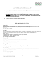
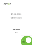
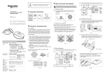
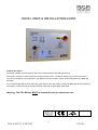
1000S+ USER & INSTALLATION GUIDE
Product description
The Merlin 1000S+ is a Gas Interlock and Electric utility isolation panel with gas proving.
The system comprises a control panel and a gas pressure sensor. The Merlin 1000S+ can receive connections
from remote emergency shut-off buttons, gas detector and CO2 monitor. It also can be integrated with a BMS and
fire alarm.
It is recommended that the user reads this guide before using the system. Please do NOT attempt to operate the
unit until the contents of this document have been read and are thoroughly understood.
Warning: The CO2 Monitor MUST be mounted close to combustion area
1
GAS SAFETY SYSTEM
1000S+
HOW TO TURN THE SYSTEM ON AND OFF
1. Turn the key switch to On position. Unit will beep and CO2 High LED will flash 3 times if CO2 Monitor is
NOT installed.
2. Gas and Electric LEDs will flash for 10secs.
3. Press relevant service button to turn required utility On or Off.
Please Note: Gas and Electric services can be turned On or Off only within 10 secs of the key
switch being turned On. After 10 secs, utility buttons will be disabled. The user must turn the key
off and back on to adjust any services.
4. To turn the system Off, turn the key switch to Off position.
EXPLANATION OF LED STATUS
Power LED
When the system is connected to the mains supply, the Red LED of the S&S Logo located in the bottom right
corner of the panel will illuminate. When no power is present, this LED will not light up.
RED = OK
OFF = No power to 1000S+
Gas LED
When the Gas button is pressed, the Gas LED will flash slowly and the Merlin 1000S+ will check the installation for
gas leaks. If gas proving is successful, the gas valve will open and the Gas LED will illuminate BLUE.
BLUE = Gas On
FLASHING SLOW = panel is checking the integrity of the gas installation
FLASHING FAST = Gas Off, Gas button enabled
OFF = Gas Off, Gas Button disabled
Electric LED
When Electric service is turned On, the Electric LED will illuminate BLUE.
BLUE = Electric On
FLASHING = Electric Off, Electric button enabled
OFF = Electric Off, Electric button disabled
Testing LED
This LED is show GREEN when the panel is checking the integrity of the gas installation.
GREEN = proving the gas line, do NOT operate any appliances
Test Fail LED
Under normal working conditions this LED is off. When the panel detects a gas leak, the LED will illuminate
YELLOW. Gas valve will remain closed.
OFF = OK
YELLOW = gas proving failed
2
GAS SAFETY SYSTEM
1000S+
Pressure Low LED
Under normal working conditions this LED is off. LED will illuminate YELLOW when pressure of the gas supply
drops below 12mBar for 10 secs. Gas valve will close.
OFF = OK
YELLOW = gas supply pressure low
Timeout LED
Under normal working conditions this LED is off. LED will illuminate YELLOW when auto-shut down has occurred.
OFF = OK
YELLOW = auto-shut down
EM Stop LED
If the Emergency Shut Off button, (either remote or on the panel) is pressed the LED will show YELLOW.
Gas and Electric services will be turned Off. The EM Stop button must be re-sert before restarting the system.
OFF = OK
YELLOW = EM Stop button pressed
Gas Detected LED
Under normal working conditions this LED is off. If Methane, Carbon Monoxide or LPG is detected (relevant gas
detector required), the LED will show RED. The Gas valve will turn Off .
OFF = OK
RED = Gas detected.
CO2 High
Under normal working conditions this LED is off. If the concentration of CO2 in the air is too high (relevant detector
required), the LED will show RED and the Gas valve will turn Off.
OFF = OK
RED = The concentration of CO2 is too high.
USING THE EMERGENCY SHUT OFF
The Emergency shut off button is located on the front of the panel. There is also a facility for remote shut off
buttons to be wired in series.
The Emergency shut off button(s) will cut off the gas supply when activated.
To reinstate the system, the Emergency shut off button(s) will need to be reset and the panel restarted.
BMS INTEGRATION
The Merlin 1000S+ can be integrated with a BMS to make or break a circuit on gas on/gas off, (valve open or valve
closed). This will tell the BMS whether or not the kitchen has use of the gas supply.
There is a blue dip-switch located on the inside facia of the Merlin 1000S+ labelled ‘BMS Selection’. This is factory
set in the ‘off’ position which signals the BMS on gas on/gas off. When switched to the ‘on’ position, the Merlin
1000S+ will only signal the BMS on a fault, i.e. CO2 high level detected, EM Stop pressed, etc.
3
GAS SAFETY SYSTEM
1000S+
FIRE ALARM INTEGRATION
The Merlin 1000S+ can be integrated with a fire alarm to close the gas supply automatically in the event of a fire.
The fire alarm can be wired in series with any remote emergency shut off buttons.
FAN SWITCH INTEGRATION
There is the facility to connect a Fan Switch (sold separately).
The Fan Switch provides the facility to turn on the fan(s) when the key switch on the Merlin 1000S+ is in the on
position and turn the power off to the fan(s) when the key switch on the Merlin 1000S+ is in the off position.
There is a blue dip-switch located on the inside facia of the Merlin 1000S+ labelled EM Selection. This is factory set
in the ‘off’ position which instructs the system to shut down the fan(s) and gas supply on activation of the
Emergency shut off button(s). On installation, this can be switched to the ‘on’ position if required. This will instruct
the system to leave the fans on and only shut off the gas supply on activation of the Emergency shut off button(s).
Note: This option is not available if Fan Switch is not installed.
GAS FILL AND PROVE TIME
Gas fill and prove times are adjustable. There are two blue dip-switches located on the inside facia of the Merlin
1000S+ labelled “Fill Time” and “Prove Time”. They are factory set in the ‘off’ position. Fill and prove time can be
changed by turning the relevant dip switch to on position.
Fill time: Off – 5 secs
On – 10 secs
Prove time: Off – 30 secs
On – 50 secs
AUTO RESET
The Merlin 1000S+ has a built-in Auto Reset feature. There is a blue dip-switch located on the inside facia of the
Merlin 1000S+ labelled “Auto Reset”. This is factory set in the ‘off’ position. When the power is restored after the
power cut, panel has to be restarted manually. On installation, this can be switched to the ‘on’ position if required.
This will instruct the system to restart automatically when power is restored after the power cut.
Note: Only Gas will be turned On when power is restored and Auto Reset is enabled.
AUTO-SHUT DOWN
The Merlin 1000S+ has a built-in Auto-shut down feature and it will turn itself off after predefined time. Auto-shut
down timeout is selectable. There are two blue dip-switches located on the inside facia of the Merlin 1000S+
labelled “Time1” and “Time2”. They are factory set in the ‘off’ position. On installation, they can be switched to the
‘on’ position to select required timeout.
Time1 Off, Time2 Off – 2 hours
Time1 On, Time2 Off – 4 hours
Time1 Off, Time2 On – 8 hours
Time1 On, Time2 On – no timeout (auto-shut down disabled)
4
GAS SAFETY SYSTEM
1000S+
On Auto-shut down gas supply will be turned Off. There is a blue dip-switch located on the inside facia of the Merlin
1000S+ labelled “Electric”. This switch is factory set in the ‘off’ position. On installation, it can be switched to the
‘on’ position. This will instruct the system to also turn off Electric service when performing Auto-shut down.
CONTACT US:
S&S Northern
Tel: +44(0) 1257 470 983
Fax: +44(0) 1257 471 937
www.snsnorthern.com
[email protected]
South East Division
Tel: +44(0) 1702 291 725
Fax: +44(0) 1702 299 148
[email protected]
5
GAS SAFETY SYSTEM
1000S+
1000SW+ Wiring Diagram
1
2
3
4
5
6
L
N
E
Pressure
Transducer
Gas Valve
Electric
Contactor
7
8
9 10
Gas
Detector
CO2
Monitor
EM
Stop
1. Mains Input 230V Single Phase.
2. Gas Solenoid Valve Power Output, 230VAC, Max 3A.
3. Electric Contactor Power Output, 230VAC, Max 3A.
4. BMS output contacts. Common, Normally Closed and Normally Open. Max.1A @ 230VAC.
5. Gas pressure transducer, power supply and returned signal (supplied).
6. Remote EM Stop buttons and Fire Alarm input wired in series (purchased separately). VOLT FREE INPUT
7. Methane, CO or LPG Detector, power supply and volt free input (purchased separately).
8. Fan Switch output (purchased separately). For wiring instruction see Fan Switch user manual.
9. CO2 Monitor (purchased separately). VOLT FREE INPUT
10. Permanent 12VDC output.
Please note, Mains wires and low voltage wires should not be
run in the same ductwork as per the LOW VOLTAGE DIRECTIVE
6
GAS SAFETY SYSTEM
1000S+