1
All procedures indicated in this manual must
be carried out by a professional installer
3 INSTALLATION AND WIRING
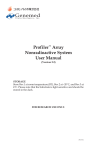
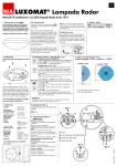
3.2.2 SAE-UE-MS-CDBWE controls staircase timer (See FIG.5).
L
N
POWER BOX
L
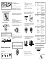
3.1 Proper Location
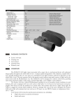
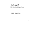
USER MANUAL
Flush Mount Dual-Load 360º
PIR Motion Sensor
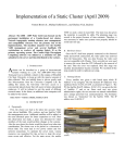
3.1.1 It is recommended to install at the height of 2.5m, and
the detection range can reach up to 7m of diameter.
(See FIG.2)
1 PACKAGE CONTENTS
SIDE VIEW
Power box
Detector
Quantity
SAE-UE-MS-IR-WE
(optional purchase)
1
Φ7m
1
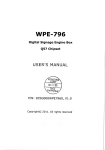
Since the detector is responding to temperature change,
please avoid the following conditions (See FIG.3):
Load
SAE-UE-MS-CDBWE (2Channels) :μ
LoadⅠ( L↓ ) for Lighting:
Incandescent lamp: max. 2000W
AC halogen lamp : max. 1000W
LV halogen lamp : max. 1000VA
Fluorescent lamp : max. 900VA/100µF
(compensated)
LoadⅡ(D1-D2) for HVAC:
Potential free contact:
Max. 5A (cosφ=1) for 250VAC or 30VDC
Motor: 1/10HP (approx.73W)
Adjustable from 10Lux to 2000Lux
Meter
Adjustment
Adjustable from approx. Φ1m ("-") to
approx. Φ7m ("+") at height of 2.5m
0 oC to +45 oC
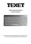
16.5
A1
Power box: 124 x 58 x 37.6mm
D1
D2
SW-3
SUPPLY VOLTAGE
A2
FAN
RJ-12
socket
Detector
RJ-12
socket
Knock-outs on protection cover is for cables entry. Please
refer to following illustration for application.
No knock-out is used: Φ0.8 - Φ1.8mm (See FIG.8A)
Knock-out on protection cover is used: Φ9 - Φ11mm
(See FIG.8B)
Detector
(opti on)
M
POWER BOX
Rated Voltage: 230V~±
10% 50Hz.
LoadⅠ( L ) for lighting: µ
Incandescent lamp: Max. 2000W
AC halogen lamp: Max. 1000W
Low halogen lamp: Max.1000 VA
Fluorescent lamp: 900VA / 100uF
LoadⅡ(D1-D2) for HVAC: Max. 10A (cosφ=1) µ
Motor: 1/10 HP (73W)
Protection degree: IP20 (powerbox), IP40(sensor)
Operating temperature: 0 C to +45 C.
D2
Environmental Detector : IP40
Power box : IP20
Protection
SW-1
SW-2
Φ8 0
58
Operating
Temperature
L
L
N
N
D1
1m signal cable
POWER BOX
LOAD
FIG.1-A
RJ-12 socket
FIG.7
N
N
RJ-12 plug
3.2 Wiring Diagrams
L1
N
360 circular , Φ7m at height of 2.5m
50 - 60mm
FIG.3
Detector: Φ80 x 52mm
L
Detection
Range
o
Dri ll a hole with
Φ=65mm on th e
ceiling
Protection cover
3.2.1.SAE-UE-MS-CDBWE for standard application (See FIG.4).
L
Lux
Adjustment
W
2.2 Dimension (See FIG.1-A & FIG.1-B)
SAE-UE-MS-CDBWE :
Time1 (for lighting): Adjustable from 5secs
to 20mins, plus test &
1S. mode
Time2 (for HVAC) : Adjustable from 10secs
to 60mins
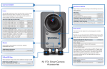
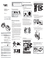
6 - 8mm
3.3.2 Unscrew protection cover on power box with
screwdriver. RJ-12 sockets are for detector s connection
and terminals are for power and load, then put the
protection cover back and screw it tightly (See FIG.7).
Auto off Timer
Adjustment
FIG.5
FIG.6
52
230V ~±10% 50Hz
SENSOR SENSOR
A
B
Rated Voltage
SAE-UE-MS-CDBWE has two relays for outputs loadⅠand
loadⅡ: loadⅠis for lighting control and loadⅡis potential free
for HVAC control (Heating, Ventilation, Air Conditioning) etc.
Easy installation in different thickness of ceiling boards.
Omni-directional detector integrated with the unique lens
provides "No dead spot" zones and superior sensitivity for
every spot zone in its 360º detection range. The detection
beams are distributed and well-concentrated over the
detection range, which enable it to detect the smallest
movement.
RJ-12 plug and socket for quick & easy connection.
Built-in red LED is used as an indicator for IR setting and easy
test operation.
124
FIG.1-B
37.6
Detector
(option)
Φ=65
The detector aiming towards the objects whose surfaces are
highly reflective, such as mirror, monitor, etc.
The detector aiming towards the objects may be swayed in
the wind, such as curtain, tall plants, miniature garden, etc.
Mounting the detector near heat sources, such as heating
vents, air conditionings, vents as dryers, lights, etc.
SAE-UE-MS-CDBWE is a ceiling flush mount presence detector
for indoor application in small-scale office and home such as
conference room, garage, kitchen, dining room etc. for lighting
and HVAC automatic control. The adjustment of time and Lux
value can be set either by its knobs or SAE-UE-MS-IR-WE IR
remote controller.
D1
D2
OUT IN
3.3.1 To install the detector, please drill a hole with a diameter
of 65mm on movable ceiling board and keep the power
cable outside. Please strip off 6-8mm of cable
sheathing for wiring (See FIG.6).
3.1.2 Helpful tips for installation
2.1 Features
Detector
RJ-12
socket
3.3 Installation Procedure
Φ7m
FIG.2
2 PRODUCT DESCRIPTION
RJ-12
socket
TOP VIEW
2.5m
Item
L
L
N
N
.
Staircase timer
CAT. NO.
SAE-UE-MS-CDBWE
SW
μ
LOAD
Pattern
TECHNICAL SPECIFICATIONS
N
Please disconnect power completely and read the
entire instruction manual carefully before installation
L2
L3
N
CONTACTOR
HEATER
Diameter for cable entry:
Φ0.8 - Φ1.8mm
FIG.4
FIG.8A
4.1.1 Time knob setting
Test Procedure
Time 1: Adjustable from 5secs to 20mins.
Time 2: Adjustable from 10secs to 60mins.
4.1.2 Lux knob setting
Diameter for cable entry:
Φ9 - Φ11mm
FIG.8B
3.3.3 Feed cables through the ceiling and refer to wiring
diagram to connect cables, then insert power box into
ceiling through the drilled hole (See FIG.9).
L ux value is adjustable from approx. 10Lux to 2000Lux.
S et Lux knob at 10Lux for the minimum Lux value,
SAE-UE-MS-CDBWE can work at dark status only.
S et Lux knob at 2000Lux for the maximum Lux value,
SAE-UE-MS-CDBWE can be triggered at any light level .
4.1.3 Meter knob setting
Set meter knob value at "-" for the smallest "field of view".
Set meter knob value at "+" for the largest "field of view".
Set meter knob value at the position between "-" and "+"
for "desired field of view".
1.Tester must be within the detection coverage.
2.Switch on the power.
3.Walk from outside across to the detection range.
Once the detector is triggered, red LED will turn on
for 2secs.
4. Adjust the detector detection angle to change coverage.
5. Adjust meter knob to change coverage.
6.Repeat step 4 to 5 until it meets user's demands.
Φ=65
Lighting
device
does not
turn on
1.Power does not
turn on.
2.Incorrect wiring.
1.Switch on the power.
3.Improper knob
setting.
4.Malfunctioned
load.
Lighting
device
does not
turn off
350 O
There is a built-in red LED as an indicator for infrared signal
reception and test mode status (See FIG.13).
LED can be used as an indicator in walk test (refer to 4.2.2) and
load does not need to be connected.
In case the SAE-UE-MS-IR-WE IR remote controller is used, the
sensor receives signal from it, then red LED will flash 2secs
quicky to indicate successful signal reception.
Signal cable
SUGGESTED SOLUTION
4.2.3 Adjust detector head
O
The detector head can be pulled down 30 and rotated
clockwise or anti-clockwise in range of 350 O (See FIG.15).
Pull out the detector head with a small screwdriver
(See FIG.16).
4.2.1 LED function
3.3.4 Put detector 's two spring clips into the drilled hole, then
insert detector upwards (See FIG.10).
POSSIBLE CAUSE
FIG.15
2.Detector is
nuisance
triggered.
FIG.16
4.2.4 The arrowhead on the detector head had been set to be
pointed one arrowhead before ex-factory. The detector
head can be clockwise or anti-clockwise rotated in the
range of 350 O. Each scale stands for 30 O .
(See FIG.17A & FIG.17B).
3.Incorrect wiring.
LED does
not turn
on
30 O
87 6 5 4 3
Spring clips
3 4 5 6 78
FIG.10
NOTE
Red LED
Adjust detector's position and assure bottom of detector
stuck firmly on ceiling (See FIG.11).
Recheck and wipe slightly with a clean and dry cloth if
detector surface is dirty.
Power box
Spring clips
FIG.17A
FIG.17B
4.2.2 Wal k test
The purpose of walk test is to select a proper installation
place to get the optimal detection range. Set meter knob at
"+", time1 knob at "TEST" (refer to step 4.1), then you can
conduct a walk test and the detector is uncontrolled by Lux
(See FIG.14).
4.2.5 The detector head can be vertically pulled 30 O downward, the different detection range can be obtained by
setting the detector head at 0 O, 10 O, 20 O and 30 O
respectively. (Each scale stands for 5 O )
(See FIG.18A & FIG.18B).
30
When the power is connected for the first time or it is resupplied
after shutting off, the detector will enter into 60secs warm up
mode. During which, LED and the load can be switched on for
60secs regardless of the time knob of detector is set to any
modes, and then off. After warming up is finished, the mode
selected will be active auto-matically.
TIME2
60 min
TIME1
1S.
10 s
TE ST
20 min
5S EC
10
4 OPERATION AND FUNCTION
LUX
20 00
Following marked values (excepting test and 1S. ) are only
for reference. You can adjust the knobs at any position you
desired (See FIG.12).
Time2
Time1
10sec
1S.
20min
15min
30min
Lux
TEST
2000
Meter
100
10min
5min
FIG. 12
There are heat
sources, highly
reflective objects or
any objects which
may be swayed in
the wind within the
detection coverage.
1.To test the delay time
specified on either
Time1 or Time2 knob
and check detector is
nuisance triggered
if lighting device does
not turn off as the
delay time is reached.
2.Keep away from
detection coverage
to avoid activating
sensor while doing
the test.
3.Make sure load and
wires are connected
correctly.
1.Walk within the
effective detection
range (Φ7 m) .
2.Switch on the power.
3.Turn the knob position
to " TEST ".
4.Refer to wiring
diagrams (FIG4)
Avoid aiming the
detector toward any
heat sources, such as
air conditioners,
electric fans, heaters
or any highly reflective
surfaces. Make sure
there are no swaying
objects within the
detection coverage.
METER
10 0
10 min
5m in
30 0
9 8 7 6 5 4 3 2 1
1 2 3 4 5 6 7 8 9
0o
FIG.18A
FIG.18B
6 OPTIONAL PURCHASE UNIT
SAE-UE-MS-CDBWE can also be controlled by the IR
remote controller SAE-UE-MS-IR-WE to make the operation
easier and more convenient (See FIG.19).
5 TROUBLE SHOOTING
10
5sec
Nui sance
triggering
2.Refer to wiring
diagrams (FIG.4 to
FIG.6) and check if
the load is malfunctioned.
3.Check if knobs are set
to the correct position,
then supply the power
to check if the LED
will turn on.
4.Replace the disabled
load with a new one.
10
15 min
30 min
4.1 Time, Lux, Meter knob
60min
2. No power
supplied.
3."Time" knob
setting isn't on
"TEST".
4. Incorrect wiring.
20o
10o
20
NOTE
3.3.5 Restore power.
1. Out of the
detection range.
FIG.13
30o
FIG.11
1. Incorrect time
setting.
30 O
4.2 Test Mode
FIG.9
PROBLEM
FIG.14
When SAE-UE-MS-CDBWE works abnormally, check
assumptive problems and suggested solutions in following
table that will hopefully to solve your problem.
SAE-UE-MS-IR-WE
300
FIG.19