1
9920-055rev_g.qxd
8/9/02
11:11 AM
Page 26
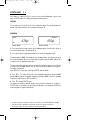
5. Test operation by pushing and releasing the piston. If the piston movement is not free or
the piston does not return easily to its rest position, the O-ring and seal are probably not
seated correctly. In this case, reinstall the piston assembly.
6. Replace the liquid end on the control module.
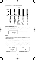
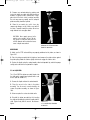
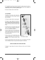
10 mL LIQUID END
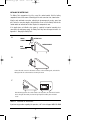
The piston seal is formed by a nitrile rubber O-ring
and fluorinated grease. Refer to Figure 10-4 and
proceed as follows:
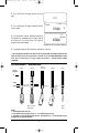
Upper
Shaft
Body
Piston
Assembly
1. Remove the liquid end from the control module.
2. Remove the upper portion of the liquid end.
Work the spring retainer beyond the threads of the
shaft. Carefully remove the piston assem-bly,
spring, guide bushing, and O-ring. Discard the worn
O-ring.
3. Remove all traces of used grease from the shaft
interior, guide bushing, and piston assembly with a
lint-free wipe. (DO NOT USE SOLVENTS.)
4. Smear a light coat of fresh fluo-rinated grease
uniformly around the piston, ensuring that no dirt is
present. Smear a light coat of grease on the new Oring and guide bushing.
5. Place the O-ring, then the guide bushing (small
end of the bushing down) on the shelf inside the
shaft body. Place the spring on top of the guide
bushing.
Seal
Spring
Guide
Bushing
O-Ring
Lower
Shaft
Body
FIGURE 10-4
10 mL LIQUID END ASSEMBLY
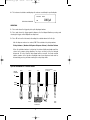
6. Wipe any foreign particles from the front surface of the cone. Carefully insert the piston
into the shaft body and snap the spring retainer down beyond the shaft threads.
CAUTION: BE CAREFUL NOT TO SCRATCH THE PISTON.
7. Replace the upper body of the liquid end, taking care not to cross the thread or
overtighten.
24