1
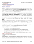
CSE325 Embedded Microprocessor Systems
Course Notes :: Part 16 - Inter-Integrated Circuit
Table of Contents
1. Serial I/O: Inter-Integrated Circuit (I2C)
1.1 Overview
1.2 Open-Collector Outputs and Wired-AND Bus Configuration
1.3 Signals and Connections
1.4 Masters, Slaves, Transmitters, Receivers.
1.5 Bus Control.
1.6 Data Transfer Modes
1.7 Multi-Master Buses
1 Serial I/O: Inter-Integrated Circuit (I2C)
1.1 Overview
[Ref: I2C61 §1–§2; Wikipedia2] The Inter-Integrated Circuit bus (I2C, I2C, IIC) was designed by Phillips Semiconductors
(now NXP Semiconductors) in 1982 for interconnecting integrated circuit chips (IC's) in electronic systems. Since 1982
there have been several revisions of the standard,
•
•
•
•
•
•
1982, Unofficial specification. Maximum bus speed was 100 Kbps (referred to as Standard Mode or Sm); slaves are
addressed using 7-bit addresses.
1992, Version 1.0. First standardized specification. Maximum bus speed increased to 400 Kbps (Fast Mode or Fm).
Added 10-bit slave addresses (which are still uncommon as of 2015).
1998, Version 2.0, 1998. Maximum bus speed increased to 3.4 Mbps (High Speed Mode or Hs-mode).
2000, Version 2.1. Minor changes to Version 2.0.
2007, Version 3.0. Added 1 Mbps (Fast Mode Plus or Fm+).
2012, Version 4.0. Maximum bus speed increased to 5 Mbps (Ultra Fast Mode or Ufm). Ufm is unidirectional only and
not backwards compatible with other modes.
Since 2012, there have been two more versions, 5.0 and 6.0, but both only corrected mistakes in prior version specifica tions. Fig. 1 shows an example of I2C bus applications.
Figure 1. Example I2C Bus Applications
1
2
I2C-bus Specification and User Manual, Rev v.6, Apr 2014
http://en.wikipedia.org/wiki/I²C
(c) Kevin R. Burger :: Computer Science & Engineering :: Arizona State University :: Fall 2015
Page 1
CSE325 Embedded Microprocessor Systems
Course Notes :: Part 16 - Inter-Integrated Circuit
Unlike SPI, which is a de facto standard, I2C is an official standard controlled by NXP. Key features of I2C include,
•
•
•
•
•
•
•
•
•
•
Only two bus lines (wires)3 leads to smaller and less expensive PCB's and IC's.
Like SPI, there are master and slave devices. However, in I 2C, there can be multiple masters on the bus. Unlike SPI,
both masters and slaves can act as transmitters and receivers (although masters always initiate a transfer).
Each device connected to the bus is identified by a unique address (SPI uses chip selects to select devices).
Half-duplex serial data transfer rates of 100 Kbps (Standard Mode), 400 Kbps (Fast Mode), and 3.4 Mbps (High Speed
Mode). Simplex serial data transfer rates up to 5 Mbps (Ultra Fast Mode).
No defined limit on the number of devices connected to the bus. In practice, the maximum number of devices is
limited by the maximum bus capacitance of 400 pF4.
IC's can easily be added and removed from the system without affecting other circuits on the bus (hot-plugging).
Since I2C is standardized, there is no variation in implementations as there may be with SPI.
In the OSI reference model, I2C is implemented primarily at the physical layer, with bus arbitration and slave acknowledgment occurring at the data link layer. Like SPI, this permits system designers to design application-specific
higher-layer software protocols.
I2C can communicate with devices that are not located on the same PCB (unlike SPI), although at slower rates.
I2C is less susceptible to noise on the bus lines than SPI.
I2C disadvantages include,
•
•
•
•
•
•
•
I2C is half-duplex.
Slower than SPI. I2C is limited to 5 Mbps in unidirectional mode and 3.4 Mbps in bidirectional mode, whereas there is
no defined limit in SPI. For example, the MKL46Z SPI1 module can transmit and receive up to 24 Mbps.
Slaves on the bus must have unique addresses. Addresses are normally 7-bits which permits addressing of up to 128
slaves. However, there are 16 reserved addresses, so only 112 are available. Addresses can be fully or partially hardwired into IC's, and since not all I 2C-enabled devices use all seven address bits, address collisions can occur. For
example, you might wish to incorporate two chips from two different manufacturers into your design. If each
manufacturer uses the same I2C address in these chips, there will be an issue when attempting to connect both of these
IC's to the bus. This can be overcome by using an I2C multiplexer5.
There is not widespread support for the higher speed modes, i.e., Hs-mode and Ufm.
I2C is shared bus and it is possible for one faulty device fail to release control of the bus, thus "hanging" the bus and
shutting down all communication. There are ways of overcoming this, but it requires a little work.
Transfers always involve fixed number of bits, specifically, 8-bits.
Due to the open-drain outputs and the requisite pullup resistors, an I 2C bus consumes more power than an SPI bus.
1.2 Open-Collector Outputs and Wired-AND Bus Configuration
[6,,7] In an IC, if an internal signal is applied to the base of a bipolar junction transistor whose collector is connected to an
output pin, while the emitter is internally connected to ground, the output is called an open-collector output, see Fig. 2,
left. In FET transistors, the terms base/collector/emitter are replaced by gate/drain/source, so the corresponding configuration is called an open-drain output, see Fig. 2, right.
For an open-drain output pin, if the n-channel FET gate-source voltage V GS is greater than the threshold voltage VGS(th) so
the transistor is on (ID ≠ 0)—thus, connecting the open-drain output pin to ground—then the output pin's state will be
low (logical 0).
3
4
5
6
7
I2C is sometimes referred to as a two wire interface (TWI).
Capacitance is the ability of a body to store electrical charge and all electrical circuits have some capacitance. As more devices are added to the I 2C bus,
the capacitance increases because there are more pins and wires connected to the bus and because the wires become longer. As the capacitance increases,
the rise and fall times of digital signals increase and this will affect bus performance. To overcome this, one trick would be to use a lower bus clock freque ncy. Section 7 of the I2C specification details other techniques that can be used to overcome increased capacitance.
For example, the Phillips PCA9540 is a 2-channel I2C multiplexer, http://simplemachines.it/Datasheets_mizar/PCA9540_6.pdf.
https://en.wikipedia.org/wiki/Open_collector
http://www.ni.com/white-paper/3544/en/
(c) Kevin R. Burger :: Computer Science & Engineering :: Arizona State University :: Fall 2015
Page 2
CSE325 Embedded Microprocessor Systems
Course Notes :: Part 16 - Inter-Integrated Circuit
Figure 2. (Left) NPN BJT Open Collector Configuration
(Right) n-Channel FET Open Drain Configuration
On the other hand, if the gate-source voltage is 0, so the transistor is off—thus, disconnecting the open-drain output from
ground—then the pin will float in the high impedance state (which is commonly represented as Z in truth tables). In the
high impedance state, it is as if the open-drain output is disconnected from the rest of the circuit.
When in the high impedance state, the voltage at the pin (relative to ground) will float (the pin will be in neither the
logical 0 nor the logical 1 state) unless some other circuit element causes it to change to 0 or 1. If the open-drain output
pin is connected via a pullup resistor8 to +V, the pin's state will be "pulled up" to a logical 1, see Fig. 3.
Figure 3. Open-Drain Output Connected to pullup Resistor
One common use of open-collector and open-drain output pins is to permit multiple pins , either on the same IC or
different IC's, to connect to a shared wire, e.g., a bus line. If the outputs of all devices connected to the bus are floating—
because the device is not trying to drive a logical 0 or 1 onto the line, then the pullup resistor will hold the line at logical
1, see Fig. 4.
Figure 4. Wired-AND Bus Configuration (Bus Signal is High)
If one or more of the devices brings its output pin low, this will connect the bus wire to the transistor's ground, thus
forcing the state of the bus line to logical 0, see Fig. 5.
8
http://en.wikipedia.org/wiki/pullup_resistor
(c) Kevin R. Burger :: Computer Science & Engineering :: Arizona State University :: Fall 2015
Page 3
CSE325 Embedded Microprocessor Systems
Course Notes :: Part 16 - Inter-Integrated Circuit
The wiring of open-collector or open-drain pins together in this way is known as a wired-AND configuration9. A wiredAND behaves like a Boolean AND logic gate in that if any one pin is low (logical 0), the bus line will be low. If all
connected pins are floating, then the bus line will be high.
Figure 5. Wired-AND Bus Configuration (Bus Signal is Low)
1.3 Signals and Connections
[I2C6 §3.1, §3.1.1; KL46-SRM Table 38-1] I2C uses two bidirectional open-drain wires, SDA (Serial Data) and SCL (Serial
Clock), each of which is connected to a positive voltage source via a pullup resistor. All devices connected to the bus share
these wires using an open-collector or open-drain configuration to form a wired-AND configuration, see Fig. 5.
1.4 Masters, Slaves, Transmitters, Receivers
[I2C6 §3.1] Devices on an I 2C bus are designated as masters or slaves. Masters initiate communications with slaves and
during a communication, the master always generates the clock signal on SCL. Unlike SPI, I 2C is a multimaster bus,
which means that there can be more than one master on the bus, although the bus can only be controlled by one master
at a time. If two or more masters attempt to acquire the bus at the same time, the I 2C arbitration procedure will allow
the winning master to acquire the bus and the others will have to wait until the bus is free to try to initiate a transfer
again.
Figure 6. I2C Bus With Multiple Masters
In a communication between a master and a slave, one device is the transmitter and the other is the receiver. The master
is not necessarily the transmitter, i.e., the master can be the transmitter and the slave can be the receiver, or the master
can be the receiver while the slave is the transmitter. This leads to four roles for I 2C devices: master-receiver, master9
Wired-AND Java applet: http://tams-www.informatik.uni-hamburg.de/applets/hades/webdemos/00-intro/03-stdlogic/wired-and.html
(c) Kevin R. Burger :: Computer Science & Engineering :: Arizona State University :: Fall 2015
Page 4
CSE325 Embedded Microprocessor Systems
Course Notes :: Part 16 - Inter-Integrated Circuit
transmitter, slave-receiver, and slave-transmitter. Obviously, in a communication, if the master is in receiver mode, the
slave has to be in transmitter mode; if the master is in transmitter mode, the slave has to be in receiver mode.
The SDA line is bidirectional, i.e., it can transmit data from master to slave or from slave to master. However,
communication is unidirectional at any time, which makes the I 2C bus half-duplex (remember, SPI is capable of fullduplex). When the bus is idle, SCL and SDA are both held high (logical 1) by pullup resistors.
Since different technology devices, e.g., CMOS transistors, NMOS transistors, and BJT transistors, can all be connected
to the bus, the levels of logical 0 and logical 1 are not fixed but rather are expressed as percentages of V DD with VL =
0.3VDD and VH = 0.7VDD.
Question: An I2C bus is integrated in a system with the MKL46Z microcontroller acting as the bus master. There are n =
5 slave peripherals connected to the bus. The MKL46Z, acting as master-trasnmitter, will independently communicate in
simplex with each of these slaves, i.e., only one at a time. How many I 2C modules must the MKL46Z contains? How many
wires are required to connect the master and each of the slaves to the I 2C bus. Do not count branches off a main wire as
a separate wire.
Answer: The MKL46Z must contain only one I 2C module which will configured to bethe bus master. The I 2C bus consists
of two wires SCL and SDA which must be connected to the MKL46Z and each of the slave peripherals. This is 2 wires,
which is O(1).
1.5 Bus Control
[I2C6 §3] Since I2C only uses two wires for clock and data, bus control logic must be transmitted using these signals.
Different states of SCL and SDA represent various conditions. In I 2C, addresses and data are transmitted msb-first.
SCL
SDA
Description
High
High
High
High
High-to-Low
High-to-Low
If a master has not obtained control of the bus, this state indicates that the bus is idle.
Master is sending a start bit (invalid if this state occurs during data transmission).
Following an ACK or NACK the master is transmitting a repeated start bit.
Figure 7. Start and Repeated Start Bits (SCL High, ↓SDA)
SCL
SDA
Description
High
High
Low
High
On the 9th clock pulse immediately following the lsb of the data byte, this is an ACK bit10.
On the 9th clock pulse immediately following the lsb of the data byte, this is a NACK bit.
Figure 8. ACK and NAK Bits (9th SCL pulse: ACK = Low, NACK = High)
10
ACK = acknowledge. NAK or NACK = not acknowledge.
(c) Kevin R. Burger :: Computer Science & Engineering :: Arizona State University :: Fall 2015
Page 5
CSE325 Embedded Microprocessor Systems
Course Notes :: Part 16 - Inter-Integrated Circuit
SCL
SDA
Description
Low
Low
High
High
High-to-Low
Low-to-High
Low
High
Data/address bit being set to 0 in preparation for next low-to-high transition on SCL.
Data/address bit being set to 1 in preparation for next low-to-high transition on SCL.
During data/address transmission, a 0 data/address bit is being transmitted.
During data/address transmission, a 1 data/address bit is being transmitted.
Figure 9. Transmitting 0 and 1 Bits
SCL
SDA
Description
High
Low-to-High
Master is sending a stop bit (invalid if this state occurs during data transmission).
Figure 10. Stop Bit (SCL High, ↑SDA)
1.5.1 Start Bit
[I2C6 §3.1.4] When a master wishes to communicate with a slave, after acquiring the bus, the master will initiate the
communication by sending a start bit which is indicated by a high-to-low transition on SDA while SCL is high.
1.5.2 Addresses and Address Transmission
[I2C6 §3.1.10, §3.1.12; KL46-SRM §38.4.1.2] Since 10-bit addresses are not widely supported, we will only discuss 7-bit
addresses. Each device on the bus must have a unique 7-bit address which permits addresses in the range 0000000 (0 10) to
1111111 (12710). Two groups of eight addresses each are reserved for specific purposes: 0000xxx (addresses 0‒7) and
1111xxx (addresses 120‒127).
Address
Dec Address
Description
0000 000 0
0
0000
0000
0000
0000
0000
1111
1111
0
1
2
3
4–7
120–123
124–127
General call address. Addresses every slave on the bus. Sending address 0000000
followed by 00000110 (0x06) tells slaves to perform a reset if the slave recognizes this
command.
START byte. For slow μc's lacking a dedicated hw I2C module and using sw polling.
C-Bus address. Permits C-Bus11 compatible devices to be attached to an I2C bus.
Reserved for different bus format. Permits I2C and other bus protocols to be mixed.
Reserved for future purposes.
Hs-mode master code.
10-bit slave addressing.
Reserved for future purposes.
11
000
001
010
011
1xx
0xx
1xx
R/W
1
x
x
x
x
x
x
C-Bus is a standard protocol for home lighting and automation, link.
(c) Kevin R. Burger :: Computer Science & Engineering :: Arizona State University :: Fall 2015
Page 6
CSE325 Embedded Microprocessor Systems
Course Notes :: Part 16 - Inter-Integrated Circuit
Slaves are constructed to monitor SCL and SDA and when a start bit is recognized, all slaves on the bus will get ready to
receive seven address bits.
1.5.3 READ/WRITE Bit
[I2C6 §3.1.10; KL46-SRM §38.4.1.3] Following the lsb of the address (the seventh transmitted bit), the master will send a
READ/WRITE bit (R = 1, W = 0). A write bit means the master wishes to transmit data to the slave and a read bit
means the master wishes to receive data from the slave. In the case of write, the roles will be Master-Transmitter and
Slave-Receiver. For read, the roles will be Master-Receiver and Slave-Transmitter. However, at the time the R/ W bit is
sent, the master is still the transmitter and the slave is still the receiver. Consequently, for a read operation, the master
and slave will switch roles. We will discuss how in a bit.
1.5.4 ACK/NACK Bit
[I2C6 §3.1.6; KL46-SRM §38.4.1.3] Following the receipt of the R/W bit (which is transmitted on the 8th clock pulse), the
master-transmitter will release SDA (by turning off the internal n-channel transistor connected to SDA; the pullup
resistor will pull SDA high) and the slave-receiver that was addressed will respond with either an ACK or NACK bit on
the 9th clock pulse by bringing SDA low (0) for ACK or letting it go high (1) for NACK. An ACK signals to the the
master-transmitter that the slave-receiver is present on the bus and ready for communication. If there is no slave-receiver
on the bus with an address matching the transmitted address, then SDA will stay high (because of the wired-AND bus
configuration, if no slave is present to bring SDA low, the pullup resistor will hold it high). This NACK tells the mastertransmitter that the addressed slave does not exist.
There are five conditions that can lead to the generation of a NACK,
1. There is no device on the bus with the transmitted address.
2. The slave-receiver is not ready to begin communication with the master-transmitter because the slave-receiver may be
busy performing some real-time function which cannot be interrupted.
3. The slave-receiver received data or commands it cannot interpret and may NACK these.
4. The slave-receiver is not able to accept more data, e.g., a buffer may be full.
5. A master-receiver NACK's the last data byte received from a slave-transmitter to indicate the end of the transfer.
1.5.5 Stop Bit
[I2C6 §3.1.4; KL46-SRM Sect §38.4.1.4] To terminate the communication, the master (whether transmitter or receiver)
will generate a stop bit following the ACK or NACK of the last data byte. The master forces SDA low shortly before
letting SCL go high. After a short interval, the master lets SDA go high. The slave recognizes this low-to-high transition
on SDA while SCL is high as a stop bit and at this time, the communication terminates. The master will keep SCL and
SDA high to put the bus back into the idle state or the master may transmit a repeated start bit to begin another com munication with the same or a different slave.
1.5.6 Transmitting Data
[I2C6 §3.1.3, §3.1.5; Fig. 6; KL46-SRM §38.4.1.3] With I 2C, all data are transmitted as bytes with the msb being sent first.
The transmitter transmits a 0-bit by driving SDA low during the low phase of SCL; a 1-bit is transmitted by letting SDA
go high when SCL is low. The receiver will sample SDA on the rising edge of SCL and if SDA is high the receiver sees a
1-bit and if SDA is low the receiver sees a 0-bit.
1.5.6.1 Clock Stretching
[I2C6 §3.1.9; KL46-SRM §38.4.1.9] During a write (or read) operation, following the ninth clock pulse and the receipt of
the ACK bit, the master-transmitter (or master-receiver) will release SCL, letting it go high. If the slave-receiver (or
slave-transmitter) cannot receive (or transmit) another data byte until it performs some internal action, e.g., servicing an
interrupt, the slave-receiver (or slave-transmitter) can force and hold SCL low to indicate to the master-transmitter (or
master-receiver) to wait. When the slave-receiver (or slave-transmitter) is ready to resume the communication, it will
(c) Kevin R. Burger :: Computer Science & Engineering :: Arizona State University :: Fall 2015
Page 7
CSE325 Embedded Microprocessor Systems
Course Notes :: Part 16 - Inter-Integrated Circuit
release SCL. When the master-transmitter (or master-receiver) sees SCL go high again, the transmission of the next data
byte will commence. See Fig. 11.
Figure 11. Clock Stretching
1.6 Data Transfer Formats
1.6.1 Master Transmit (Write Operation)
[I2C6 §3.1.10, Fig. 11; KL46-SRM §38.4.2.1] In this format, the master acts as master-transmitter to transmit data to a
slave-receiver.
Figure 12. Master-Transmit Operation
1.6.2 Master Receive (Receive Operation)
[I2C6 §3.1.10; Fig. 12; KL46-SRM §38.4.2.2] In this format, the master acts as master-receiver to receive data from a
slave-transmitter. For the master to receive data from the slave, the master initiates the communication as mastertransmitter with the slave being slave-receiver. The communication begins with the master transmitting the start bit, the
slave address, and the R/W bit set to 1 (for read). The addressed slave responds with an ACK, and at this time, the roles
are reversed with the master becoming the receiver and the slave becoming the transmitter.
Figure 13. Master-Receive Operation
Data bits are transmitted by the slave-transmitter on the clock pulses generated by the master-receiver. After the lsb of
each data byte is received, the master-receiver generates an ACK to indicate reception. The slave-transmitter continues
sending data bytes with the master-receiver ACKing each byte. The communication is terminated by the master
NACKing the last data byte—which informs the slave to stop transmitting—followed by the master generating the stop
bit.
1.6.3 Combined Transfer
[I2C6 §3.1.4, §3.1.10; Fig. 13] A combined transfer can involve repeated transmissions to the same or different slaves,
repeated receives from the same or different slaves, or multiple receives and transmissions to the same or different slaves,
all while the master maintains control of the bus.
(c) Kevin R. Burger :: Computer Science & Engineering :: Arizona State University :: Fall 2015
Page 8
CSE325 Embedded Microprocessor Systems
Course Notes :: Part 16 - Inter-Integrated Circuit
For example, suppose that the master is going to first transmit to slave S1 and then receive from slave S2. The
communication begins with the master-transmitter transmitting the start bit, the address of slave S1, and the R/ W bit =
0. The data transfer then continues as described in §1.6.1.
Figure 14. Combined Transfer Operation
Following the ACK of the last data byte from slave-receiver S1, the master-transmitter generates a repeated start bit (Sr)
by holding SCL high and making a high-to-low transition on SDA. Following Sr, the master-transmitter transmits the
address of S2 and R/W = 1. S2 responds with an ACK at which time the master-transmitter becomes master-receiver and
S2 becomes slave-transmitter. The data transfer continues as described in §1.6.2.
1.7 Multi-Master Buses
Multiple master devices can be connected to an I2C bus, and the operation of one master is no different than the operation
of any other. Since masters initiate all communications, problems can ensue if two masters attempt to simultaneously
acquire the bus. To solve the problem, clock synchronization and arbitration are implemented.
1.7.1 Clock Synchronization
[I2C6 §3.1.7; KL46-SRM §38.4.17] Suppose two masters M1 and M2 both attempt to initiate a communication at the same
time12. With SCL and SDA high, both masters see the bus is idle and each will hold SCL high and drive SDA low to send
a start bit. The standard specifies that SDA must be held low for a minimum of 4 μs in Standard Mode, 600 ns in Fast
Mode, 260 ns in Fast Mode Plus, and there is no specified maximum 13.
Shortly thereafter, each master is going to begin transmitting the address bits of the slave that each master is trying to
communicate with. We will discuss arbitration—the procedure that is followed to determine which of two or more
competing masters is permitted to acquire the bus—in the next section, but before arbitration can begin, the masters
must synchronize their clocks.
Remember, masters generate the clock signal during communication, and M1 and M2 may be communicating with slaves
at different bit rates, so the clock frequencies of M1 and M2 may differ. Let's suppose M1's clock frequency is higher than
that of M2, which means that the period of M1's clock will be shorter than the period of M2's clock.
At time t = 0, suppose M2 sees the bus is idle and initiates a communication by driving SCL low. Because of the wiredAND configuration of the bus, all other devices see SCL go low, and at this time each bus device—M1 included—will
configure its internal clock generator to start counting off the low part of its clock cycle, see Fig. 15.
After counting off its low period, M1 will attempt to release SCL to begin counting off its high part. However, since M1's
12
13
The competing masters most likely will not attempt to acquire the bus at the same exact moment in time, so what we mean by "same time" is, "at times
that are pretty darn close together." For example, suppose we are using 100 Kbps Standard Mode and master M1 sees both SCL and SDA high. M1 will
hold SCL high and will begin to drive SDA low to transmit a start bit. Now, digital signals do not change from high to low (or low to high)
instantaneously (although we wish they would). Rather, the voltage will drop from high (above 0.7V DD) to an intermediate-neither-high-nor-low-state
(between 0.3VDD and 0.7 VDD)and then finally to low (below 0.3V DD). The time it takes for this to happen is called the fall time, tf, and for Standard Mode
I2C, tf must not exceed 300 ns (see Table 10 on page 48 of the I2C-bus Specification). Therefore, it is not only conceivable, but entirely likely that another
master M2 could sample SDA 10-50 ns after M1 has begun driving it low, but M2 will be sampling SDA while the voltage level is still in the range that
M2 would see SDA as high. Thus, M2 will see the bus as idle and will also begin driving SDA to transmit a start bit.
See parameter THD;STA in Table 10 on p. 48 of the I2C-bus Specification.
(c) Kevin R. Burger :: Computer Science & Engineering :: Arizona State University :: Fall 2015
Page 9
CSE325 Embedded Microprocessor Systems
Course Notes :: Part 16 - Inter-Integrated Circuit
period is shorter than M2's, M2 will still be counting off its low period and will keep SCL low (because of the wired-AND
configuration). Since M1 attempted to release SCL but it sees SCL is still low, M1 now knows that some other master is
keeping SCL low. Therefore, M1 will enter a wait state, i.e., M1's clock generator will be paused, until M2 releases SCL
and M1 sees it go high. At this time, both M1 and M2 begin counting off the high part of their clocks. M1 will reach the
end of its count first (because M1's period is shorter) and will drive SCL low. M2 will see SCL go low and will synchronize
its internal clock generator to begin counting off its low period, at which point the process repeats. Therefore, M1 and M2
have synchronized their clocks with M2 determining the length of the low period of the synchronized clock signal on SCL,
and M1 determining the length of the high period of SCL. Note that the I 2C clock does not have to have a 50% duty cycle
because bits are transferred on rising clock edges.
Figure 15. Clock Synchronization
1.7.2 Arbitration
[I2C6 §3.1.8; KL46-SRM §38.4.1.6] Once M1 and M2 have simultaneously synchronized their clocks and sent the start bit,
arbitration determines which of M1 or M2 is permitted to acquire the bus and complete its transmission. The master that
loses arbitration will stop driving SCL and SDA and will wait until the bus becomes idle to try again.
Arbitration proceeds bit by bit. Following the start bit, each master will begin placing address bits on SDA, one per
(synchronized) clock pulse. After placing its bit on SDA, each master will sample SDA to see if SDA matches what the
master expects to see. For example, if the address of the slave being contacted by M1 is 0010010 and the address of slave
being contacted by M2 is 0010000, then both M1 and M2 will put a 0 onto SDA (it will be low). Both M1 and M2 will
sample SDA after forcing SDA low and will see that it is indeed low, so M1 and M2 both will assume they have control of
the bus and will continue transmitting address bits, one after the other. Eventually, M1 will place bit 1 of its slave
address, which is 1, on SDA but M2 will force SDA low to transmit a 0 bit. When M1 samples SDA it will see a 0 rather
than a 1. At this point, M1 knows that it has lost arbitration and will stop transmitting to become a slave-receiver. M2's
communication with the slave will continue with no interruption, i.e., it will proceed to send any remaining address bits
followed by the R/W bit.
If M1 and M2 happen to both be transmitting to the same slave, then there will be no mismatch in the address bits, and
arbitration will continue into the data bits. The first master to transmit a 1-bit will lose arbitration to the master
transmitting a 0-bit. Because of the way arbitration proceeds, it is entirely possible for two masters to send the same data
to the same slave without knowing that another master is also sending the same data to the same slave.
(c) Kevin R. Burger :: Computer Science & Engineering :: Arizona State University :: Fall 2015
Page 10
CSE325 Embedded Microprocessor Systems
Course Notes :: Part 16 - Inter-Integrated Circuit
However, the following conditions are undefined if arbitration is still proceeding while one master is still sending data bits,
•
•
•
Master M1 sends a repeated start bit and master M2 transmits a data bit.
Master M1 sends a stop bit and master M2 transmits a data bit.
Master M1 sends a repeated Start bit and master M2 sends a stop bit.
The I2C-bus Specification does not state what should be done in these cases so it would be wise to avoid them.
(c) Kevin R. Burger :: Computer Science & Engineering :: Arizona State University :: Fall 2015
Page 11