1
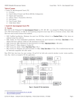
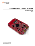
CSE325 Embedded Microprocessor Systems
Course Notes :: Part 3 - Intro the MKL46Z Microcontroller
Table of Contents
1 Introduction to the Kinetis MKL46Z Microcontroller
1.1 ARM Architecture
1.2 MKL46Z Part Number
1.3 Features
1.4 Ratings and Operating Characteristics
1.5 Power Consumption
1 Introduction to the Kinetis MKL46Z Microcontroller
In this section we will discuss information about the MKL46Z microcontroller and the FRDM-KL46Z board that is
documented in the data sheet [KL46-SDS] and schematic [FRDM-KL46-SCH].
1.1 ARM Architectures
[Ref: 1,2] The MKL46Z microcontroller is based on an ARM Cortex-M0+ processor architecture. The ARM processor
architecture derives from a British computer manufacturer, Acorn Computers, which developed the Acorn RISC Machine
(ARM) architecture in the early 1980's for use in their series of BBC Micro 3 personal computers. The ARM architecture
was inspired by the University of California Berkeley RISC architecture that was developed in the late 1970's to early
1980's. In 1990, Acorn spun off the ARM design team into a new company named Advanced RISC Machines, Ltd., which
became ARM Ltd. in 1998 when Advanced RISC Machines went public. ARM Ltd., is a subsidiary of ARM Holdings.
Over the years, the ARM architecture has progressed with these milestone architectures.
ARM1 Family, ARMv1 Architecture
First implementation of the ARM1 family. 32-bit data bus; 26-bit address space (permitting access to 64 MiB of memory,
which was a huge amount in those days); 27 32-bit registers; 30,000 transistors; no cache. Implements the 32-bit ARM
instruction set.
ARM2 Family, ARMv2 Architecture
Added the MUL (multiply instruction). No divide instruction.
ARM2 Family, ARMv2a Architecture
Added an integrated memory management unit (MMU), graphics, and I/O processing. 8 MHz.
ARM3 Family, ARMv2a Architecture
Added 4 KiB unified cache (instructions and data are cached together). 25 MHz.
ARM6 Family, ARMv3 Architecture
Expanded the memory address space to 32-bits. Support for a floating point coprocessor. 33 MHz.
ARM7 Family, ARMv3 Architecture
Expanded the cache to 8 KiB unified. 40 MHz.
ARM7T Family, ARMv4T Architecture
Added a 3-stage pipeline. Dropped legacy support for 26-bit memory addressing. Added a Memory Protection Unit
(MPU) which requires user code and kernel code to run with different privileges. 59.8 MHz
ARM7EJ Family, ARMv4T Architecture
Expanded the pipeline to 5 stages. Added the Thumb instruction set (instructions are 16-bits rather than 32-bits). Added
Jazelle support which permits the processor to natively execute Java bytecode.
1
2
3
https://en.wikipedia.org/wiki/ARM_architecture
https://en.wikipedia.org/wiki/List_of_ARM_microarchitectures
https://en.wikipedia.org/wiki/BBC_Micro
(c) Kevin R. Burger :: Computer Science & Engineering :: Arizona State University :: Fall 2015
Page 1
CSE325 Embedded Microprocessor Systems
Course Notes :: Part 3 - Intro the MKL46Z Microcontroller
ARM8 Family, ARMv4 Architecture
5-stage pipeline. Added static branch prediction. Double-bandwidth memory. 72 MHz.
ARM9T Family, ARMv4T Architecture
Added 16 KiB instruction and 16 KiB data caches. 180 MHz.
ARM10E Family, ARMv5 Architecture
Expanded the pipeline to 6 stages. Added enhanced Digital Signal Processing (DSP) instructions. 32 KiB I-cache and 32
KiB D-cache.
ARM11 Family, ARMv6 Architecture
8-stage pipeline. Added Single-Instruction Multiple-Data (SIMD) instructions. Up to 665 MHz.
Cortex-M Family, ARMv6 and ARMv7 Architectures
M = microcontroller profile (supports fast interrupt processing, hardware stacking of registers [when an exception occurs,
certain hardware registers will be pushed onto the runtime stack; supports multiple stacks], interrupt handlers can be
written in a HLL; the processor is designed to be integrated into an FPGA and is ideal for very low power applications).
Added Thumb-2 instructions (Thumb-2 instructions are 32-bit but can be freely mixed with 16-bit Thumb instructions).
Optional system timer. Optional bit-banding memory. Optional cache. Cortex-M architectures based on ARMv6 support
hardware multiply but not divide; ARMv7 chips support hardware divide. Within the Cortex-M family are the CortexM0, Cortex-M0+, Cortex-M1, Cortex-M3, Cortext-M4 and Cortex-M7 cores. The MKL46Z implements a Cortex-M0+
core employing the ARMv6M architecture.
Cortex-R Family, ARMv7R Architecture
R = real-time profile (implements a traditional ARM architecture with multiple modes (user, kernel, etc) and supports
memory protection with a Memory Protection Unit (MPU).
Cortex-A Family (32-bit), ARMv7A Architecture
A = application profile (implements a traditional ARM architecture with multiple modes and supports a virtual memory
system based on a MMU).
Cortex-A Family (64-bit), ARMv8 Architecture
The most recent and the first 64-bit architecture.
ARM Holdings does not manufacture and sell microprocessors. Rather, they design the microprocessor architecture and
license the technology as IP (intellectual property) to chip manufactures such as Freescale, Samsung, Toshiba, and so on.
Usually this is in the form of synthesizable Verilog code.
1.2 KL46 Part Number
[Ref: KL46-SDS §7.2] The microcontroller on our Freedom KL46Z boards is a Freescale Kinetis microcontroller, part
number MKL46Z256VLL4. The general format for Freescale Kinetis part numbers is Q KL## A FFF R T PP CC N where,
Q = M
KL## = KL46
A = Z
FFF = 256
R = blank
T = V
PP = LL
CC = 4
N = blank
The chip is fully qualified for market.
Kinetis family is KL46. The L series of microcontrollers are designed for ultra-low power applications.
Z = the core microprocessor implements the ARM Cortex-M0+ architecture.
256 = 256 KiB flash ROM. MKL46Z128VLL4 is the same, but with 128 KiB of flash of 16 KiB SRAM.
Silicon revision (first).
V = temperature range is -40° to 105° C.
Package identifier. LL = 100 pin low quad flat pack (LQFP).
4 = maximum CPU frequency is 48 MHz.
Packaging type.
We will simply refer to the chip as the MKL46Z.
(c) Kevin R. Burger :: Computer Science & Engineering :: Arizona State University :: Fall 2015
Page 2
CSE325 Embedded Microprocessor Systems
Course Notes :: Part 3 - Intro the MKL46Z Microcontroller
1.3 Features
[Ref: KL46-SDS; KL46-SRM §2.1.1] Refer to p. 1 of the data sheet and §2.1.1 of the KL46-SRM.
•
•
•
•
•
•
•
•
•
•
•
•
•
•
•
•
•
•
•
•
•
•
•
•
•
48 MHz ARM Cortex-M0+ architecture.
256 KiB flash ROM and 32 KiB static RAM (SRAM).
Nine low-power modules to reduce power consumption.
Computer Operating Properly (COP) watchdog timer.
4-channel Direct Memory Access (DMA) controller.
Serial Wire Debug (SWD) debugging interface and Micro Trace Buffer (MTB).
Bit Manipulation Engine (BME).
Operating characteristics: Voltage range 1.71 to 3.6V (3.3V on the FRDM-KL46Z board).
Segment LCD controller (SLCD).
Touch sensor interface (TSI).
Up to 84 GPIO pins.
USB OTG controller.
Two 16-bit Serial Peripheral Interface (SPI) modules.
Two Inter-Integrated Circuit (I2C) modules.
One Integrated Interchip Sound (I2S) module.
One low power Universal Asynchronous Receiver Transmitter (UART) module (UART0).
Two UART modules (UART1 and UART2).
One 16-bit successive approximation analog-to-digital converter (SAR ADC).
One 12-bit digital-to-analog converter (DAC).
Analog comparator (CMP),
One 6-channel Timer/Pulse Width Modulation (TPM) module.
Two 2-channel TPM modules.
Periodic Interrupt Timers (PIT).
Real-Time Clock (RTC) module.
80-bit unique identification number, stored in read-only hardware registers.
1.4 Ratings and Operating Characteristics
[Ref: KL46-SDS, 4] The technical data sheet for an IC will provide all sorts of information on operating characteristics. We
will not look at all of these, but we will discuss a few that are relevant.
Turn to §1.4 in the SDS. Table 4 lists voltage and current operating ratings. These are provided as minimums and
maximums and they define the safe operating levels for various parameters. If these parameters are not met (a parameter
is below the minimum) or are exceeded (a parameter is above the maximum), then the chip is not guaranteed to continue
operating correctly, and you may find yourself with a melted glob of silicon attached to your board. For example,
Parameter
VDD
IDD
VIO
ID
VDDA
1
2
4
Description
Digital supply voltage
Digital supply current
I/O pin, voltage input
Instantaneous maximum current, single pin1
Analog supply voltage2
Min
-0.3
—
-0.3
-25
VDD - 0.3
Max
3.8
120
VDD + 0.3
25
VDD + 0.3
Units
V
mA
V
mA
V
Applies to all port pins.
This is the supply voltage to the analog-to-digital converter (ADC).
http://www.ti.com/lit/an/szza036b/szza036b.pdf
(c) Kevin R. Burger :: Computer Science & Engineering :: Arizona State University :: Fall 2015
Page 3
CSE325 Embedded Microprocessor Systems
Course Notes :: Part 3 - Intro the MKL46Z Microcontroller
Note that some currents are listed as negative, see min I D and some as positive, see max I D. A μc pin can either sink or
source current5. It sinks current if current is flowing into the device on the pin and it sources current if current is flowing
out of the device on the pin. When the pin is sourcing current, the current will be specified as negative and when it is
sinking current, it will be specified as positive (the - and + signs simply indicate the direction of current flow, there is no
such thing as -25 mA of current). Consequently, I D means that a single pin can sink no more than 25 mA, nor source more
than 25 mA, and that violating this rating will generally cause the chip to fail.
Fig. 2 in §2.1 documents rise time, fall time, and when a signal is considered high and when low. If VIH = 3.3V and VIL =
0V, then fall time is defined to be the time it takes for the signal to transition from 80% of V IH to 20 of VIH. Rise time is
just the inverse; it is the time for the signal to change from 20% of V IH to 80% of VIH. Since VIH = 3.3V on our board,
then fall time is the time for the signal to fall from 2.64V to 0.66V; rise time is the time for signal to rise from 0.66V to
2.64V. The midpoint is the voltage level between V IH and VIL and is defined to be VIL + (VIH - VIL) / 2; at 0V and 3.3V
for VIL and VIH the midpoint would be 0 + (3.3 - 0) / 2 = 1.65V. The signal is considered low when the voltage is below
0.66V and is considered high when it is above 2.64V. Between 0.66V and 2.64V, the signal is neither high nor low.
Next, Table 5 in §2.2.1 lists normal voltage and current operating requirements. These numbers specify minimums and
maximums for various parameters. For example, V DD (the supply voltage) is defined to be between 1.71V and 3.6V. Note
that Table 4 defined VDD to be between -0.3V and 3.8V. The difference between the two sets of numbers is that Table 5
documents where you should normally keep V DD at; if, occasionally, for a brief amount of time, V DD goes over 3.6V, but
not over 3.8V, then the chip will continue operating properly. However, if V DD goes over 3.8V for an extended amount of
time, bad things are guaranteed to happen.
Turn to the table in §5.1. The MKL46Z256VLL4 is manufactured in a 100-pin LQFP package. Pins 8, 30, 48 are V DD
(3.3V) and pins 9, 29, 49, 74 are V SS (0V or ground). Open the KL46Z schematic [FRDM-KL46Z-SCH] and turn to sheet
3. U4 is the MKL46Z μc. Locate pins 9, 29, 49, and 74 in the lower-right corner of U4; these pins are labeled VSS1, VSS2,
VSS3, and VSS4. Note that each pin is connected to ground. Now, locate pins 8, 30, and 48 on the upper-right corner of
U4. Note that those pins are labeled VDD1, VDD2, and VDD3. Each of those pins is connected to a signal that is labeled
P3V3_KL46Z.
Let's see how power is routed to the MKL46Z. Power is provided to the board via the USB cable that connects the PC to
the board. This USB cable is plugged into connecter J13, see sheet 4. A mini-B USB cable carries five signals. The only
two we are interested in are pin 5 (ground) and pin 1 (+5V); on the schematic pin 1 is connected to a signal that is
labeled P5V0_SDA_USB_CONN_VBUS. This signal is connected to an inductor, L4, and on the other end of L4 the
signal becomes P5V_SDA. P5V_SDA is routed various places, including to sheet 5 (the box in the upper right corner).
From there, it travels through a (Schottky) diode, and is fed into U1 on pin 3; U1 is an On Semiconductor voltage
regulator, part number NCP11176. A voltage regulator7 is a circuit which is designed to produce and maintain a constant
voltage (the voltage coming into the voltage regulator may be "bouncing" around a bit; this is referred to as noise8). The
output from the NCP1117, on pin 2, is now labeled P3V3_VREG and is at +3.3V (with less noise). From there, the
signal travels through another Schottky diode and finally leaves the block where the signal is now named P3V3_KL46Z.
From there, it travels back to U4 and is connected to the VDD pins of the μc.
By the way, notice that in the same block on sheet 4, there is a signal labeled P3V3 (also, +3.3V). This power signal is
routed several place on the board, e.g., it powers the green and red LED's on sheet 3. It also travels to the Arduino I/O
headers on sheet 5. In particular, it is connected to pins 6 and 8 of jumper J3. Therefore, we will use J3 pins 6 and or 8 to
route 3.3V to our breadboard when we construct external circuits for some of the lab projects. Note also, that pins 14 and
16 of J3 are grounded. We will also run a wire from J3 to our breadboard to provide ground for our circuits.
5
6
7
8
https://en.wikipedia.org/wiki/Current_sources_and_sinks
http://www.onsemi.com/pub_link/Collateral/NCP1117-D.PDF
https://en.wikipedia.org/wiki/Voltage_regulator
https://en.wikipedia.org/wiki/Noise_(electronics)
(c) Kevin R. Burger :: Computer Science & Engineering :: Arizona State University :: Fall 2015
Page 4
CSE325 Embedded Microprocessor Systems
Course Notes :: Part 3 - Intro the MKL46Z Microcontroller
Now, back to Table 5 in the data sheet and the remaining relevant operating parameters. V DDA is the supply voltage to
the ADC (analog-to-digital converter) circuit in the μc (see SRM §28.2.1). Turn to sheet 3 and locate U4 pin 22, which is
labeled VDDA. Note that P3V3_KL46Z powers it as well. Per Table 5-1, V DDA has the same minimum and maximum as
VDD.
VIH is the input high voltage. This parameter represents the voltage at a GPIO pin when it is configured for input and
and an external device is driving it high (or logical 1). That is, the voltage at the device is at a higher potential then the
pin (remember that voltage is specified between two points in a circuit; when we say the voltage at point x it is implied
that the voltage is between point x and ground). There are two values listed for V IH; the first one is for when V DD is in the
range 2.7V to 3.6V and the second one is when V DD is in the range 1.7V to 2.7V. Since on our board, V DD = 3.3V, the top
number is applicable, and this value states the a input pin will read as 1 when the voltage on the pin is at least 70% of
VDD. Since VDD = 3.3V on our board, this means the pin will be read as 1 when V IL is greater than or equal to 2.31V (we
are looking in the min column).
VIL is the input low voltage. This parameter represents the voltage at a GPIO pin when it is configured as an input pin
and and external device is driving it low (or logical 0). Again, the top number is applicable, so V IL must be less than or
equal to 35% of VDD or 1.155V (we are looking in the max column).
For example, if an external device is connected to this pin, and the voltage potential between the device and the pin is
2.31V or higher, we will read the state of the pin as 1. If the voltage at the pin is below 1.155V, we will read the state of
the pin as 0. If the voltage is between this minimum and maximum, the state of the pin is indeterminate. It may read as 0
or as 1.
VODPU is the open drain pullup voltage. We may discuss open drain connections later in the course, so I will not go into
the details now, but note that VODPU must be VDD, i.e., +3.3V.
Now turn to Table 7 in §2.2.3. The relevant parameters in this table are V OH, IOHT, VOL, IOLT, and RPU. Starting with VOH,
which is the output high voltage when the μc is driving the pin high, this value represents the minimum voltage that an
output pin must be at in order to be considered high (somewhere external to the μc, the pin must be connected to ground
in order for current to flow out of the μc). When VDD is between 2.7V and 3.6V and the μc is sourcing 5 mA of current,
VOH must be at least VDD - 0.5 or 3.3V - 0.5V = 2.8V. Note, there are two values for V OH: normal pad drive strength and
high pad drive strength. These refer to the amount of current that the device can source on this pin. In high pad drive
strength, the pin can be configured to source a higher current than it does under normal conditions (the maximum is 25
mA; see ID in Table 4). Note 1 in the Table tells us that GPIO pins PTB0 (port B, pin 0), PTB1, PTD6, and PTD7 can
be configured for normal or high pad drive strength; all other GPIO pins are normal drive strength only.
IOHT is the output current high total for all ports. What this means is that if several GPIO pins have been configured to
source current, the sum total of all of the currents leaving those pins cannot exceed 100 mA. If it does, the chip may fail;
if it does not fail, it will most certainly become quite hot.
VOL is the output low voltage. This parameter represents the voltage at a GPIO pin when it configured as an output pin
and is to be 0. A pin is brought low by internally grounding it. In this case, with 5 mA of current flowing into the pin, the
voltage between the output pin and an external device must be no more than 0.5V for the pin to be considered low.
IOLT is the output low current total for all pins. This is similar to I OHT. For pins configured as output that are sinking
current, the maximum is 100 mA. Again, exceeding this rating will cause your chip to catch fire.
Finally, RPU is the rating for the internal pullup resistors 9 which can be enabled when required. We will discuss this
concept in more detail later. Notice that the internal pullup resistor is rated a a maximum of 50 kΩ.
9
https://en.wikipedia.org/wiki/Pull-up_resistor
(c) Kevin R. Burger :: Computer Science & Engineering :: Arizona State University :: Fall 2015
Page 5
CSE325 Embedded Microprocessor Systems
Course Notes :: Part 3 - Intro the MKL46Z Microcontroller
1.5 Power Consumption
[Ref: KL46-SDS; KL46-SRM Ch. 7] Turn to Table 9 which describes power consumption operating behaviors. I DD_RUNCO
represents the μc power consumption when the core (the ARM Cortex-M0+ microprocessor within the MKL46Z)
frequency is 48 MHz, the flash clock (which serves the flash controller) is 24 MHz, and the bus clock (which is routed to
various peripheral devices) is disabled, and an infinite loop is being executed with the code stored in flash. The typical
value is 4.5 mA and the maximum that was detected during testing was 5.1 mA.
IDD_RUN represents power consumption when the core clock is 48 MHz, the bus and flash clocks are 24 MHz, clocks are
being routed to all peripherals, code is being executed from flash, and V DD = 3V. At 25° C, the value is typically 6.9 mA,
but was measured under test as high as 7.1 mA. This is a relatively minimal amount of current; remember, the L in KL46
represents an ultra-low power processor.
The MKL46Z, like most sophisticated μc's and μp's, can operated in different power saving modes. Ch. 7 Power
Management in KL46-SRM discusses these modes and how to enable them. However, we do not have time to delve into
the details. You will notice from a quick glance at the table that power consumption can be reduced to no more than 0.69
μA (1/1000 of a mA) at 25° C in very low-leakage stop mode. In this mode, the chip is barely alive; only a small part of
the core would be activated, which would be checking for some event to occur that will transition the chip out of this
mode.
See Fig. 3 in KL46-SDS which illustrates power consumption at V DD = 3V as a function of the core clock frequency. The
MKL46Z core can be configured to run at various clock frequencies. The maximum clock frequency is 48 MHz, and Fig. 3
shows that under normal operating conditions, with the clock enabled to all μc peripherals, the power consumption is
approximately 7.4×10⁻³ A = 7.4 mA. Halving the clock frequency to 24 MHz, would lower power consumption to
approximately 5.2 mA. Notice that once 4 MHz is reached (2.5 mA) that further core clock frequency reductions do not
result in as significant savings in power. To conserve more power, we would have to configure the chip to enter one of the
power saving modes.
(c) Kevin R. Burger :: Computer Science & Engineering :: Arizona State University :: Fall 2015
Page 6
CSE325 Embedded Microprocessor Systems
Course Notes :: Part 3 - Intro the MKL46Z Microcontroller
References
[ARM-ARM]
[ARM-CALL]
[ARM-ISQR]
[ARM-M0+DUG]
[ARM-M0+TRM]
[ARM-V6M]
[BARR]
[BERGER]
[CW-BUILD]
[FRDM-KL46-PIN]
[FRDM-KL46Z-QSG]
[FRDM-KL46-SCH]
[FRDM-KL46Z-UM]
[HEATH]
[KL46-SDS]
[KL46-SRM]
[NOER]
[OPENSDA]
[VAHID]
[WHITE]
ARM Architecture Reference Manual, Rev I., ARM, 2005.
Procedure Call Standard for the ARM Architecture, Rev. E 2.09, ARM, 2012.
ARM and Thumb-2 Instruction Set Quick Reference Card, Rev. M, ARM, 2008.
Cortex-M0+ Device User's Guide, ARM, 2012.
Cortex-M0+ Technical Reference Manual, Rev. r0p1, ARM, 2012.
ARMv6-M Architecture Reference Manual, Rev. C, 2010.
Barr, M., Programming Embedded Systems in C and C++, O'Reilly, 1999.
Berger, A, Embedded Systems Design, CMP Books, 2002.
CodeWarrior Kinetis Build Tools Reference Manual, Rev. 10.6, Freescale, 2014.
FRDM-KL46Z Pinout.
FRDM-KL46Z Quick Start Guide, Rev. 1, Freescale, 2013.
FRDM-KL46Z Schematic, Rev. C, Freescale, 2013.
FRDM-KL46Z User's Manual, Rev. 1.0, Freescale.
Heath, S., Embedded Systems Design, 2nd ed, Newnes, 2003.
Kinetis KL46 Sub-Family Data Sheet, Rev. 5, Freescale, 2014.
Kinetis KL46 Sub-Family Reference Manual, Rev. 3, Freescale, 2013.
Noergaard, T., Embedded Systems Architecture, 1st ed, Newnes, 2005.
OpenSDA User's Guide, Rev. 0.93, Freescale, 2012.
Vahid, F., and Givargis, T., Embedded System Design, John Wiley & Sons, 2002.
White, E., Making Embedded Systems, O'Reilly, 2011.
(c) Kevin R. Burger :: Computer Science & Engineering :: Arizona State University :: Fall 2015
Page 7