1
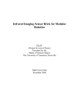
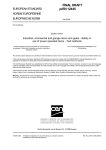
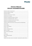
Installation Instructions
for the garage door operator
TS Solar I
TS Akku I
This booklet must be handed over to the end-user
together with the user-manual.
1V1
English
Content
Information and Remarks
Remote Control
Directives and Regulations
Use of the operators
Garage Doors
The installers declaration of conformity
Older Garage Doors
Important Information for the Installer 3
Instruction for the users
Security Advises for the Installation 4
Programming the Hand Transmitters 18
Basics
Programming Transmitter and Receiver
Clearing the receivers‘ memory
Additional Information 19
Using the remote-control
Criterias influencing the range
Use with a HomeLink© System
Installation
Technical Information
Different Conditions for Installation 5
Minimum space above the garage door
Door Arm Extension
C-Rail Extension
Pre-Mounting the operator 6
Installing the operator 6
Minimum head room above the door
Adjusting the running-length blocks
Technical Data
Wiring
Messages from LED-lamps and operators lighting 21
Status Messages
Error Messages
Messages from the red LED-lamp and the operators lighting
Additional Messages only from the red LED lamp
8
The Emergency Release 9
When there is a second entrance to the garage
When the garage door is the only entrance
The Solar Components
TS Solar: Mounting the Solar Panel
TS Solar: Using the Solar Panel
TS Solar: Power Cord
10
11
11
Printed Circuit Board: Adjustments and Connections
Before Usage: Connecting the Battery Cable
12
Devices for Adjustments 12
TEST-Button (1)
LEARN-Button (2)
Combined TEST + LERN button functions
Programming Running-Length and Force 13
Information
1.) Adjusting the running-length blocks
2.) Starting the programming-mode
3.) Start the learning-cycle
Quick Reference
Special Functions 14
Readjusting the time for the internal light
Setting the pre-warning ON/OFF
Programming the Soft-Modes
The BOTTOM Soft-Stop
Programming the BOTTOM Soft-Mode
Disabling the TOP Soft-Modes
External Connections 16
Push Button and Key Switch
12V DC Supply
Receiver-Module
Advanced Connections 16
Photocell without self-test
Photocell with self-test
Safety-Beam, Hatch-Door and Emergency Stop
Opto Sensoric Components
DIP-Switches 17
TOP Soft-Mode enabled/disabled
Force during the last 500mm before reaching closing limit
Side Hinged Door
2
20
20
Information and Remarks
Important Information for the Installer
It is within legal regulation and without restriction, to use a
Seip door operator with any garage door that has been approved for use with other certified door operators!
Directives and Regulations
The garage door operator TS Solar/TS Akku complies to the latest
European directives and regulations. The declaration of conformity
is enclosed at the end of these instructions.
Use of the operators
The operators were designed for the use with up-and-over doors
(tilting and canopy-type) and sectional doors.
All garage doors need to be maintained before automation. The
door must be easily opened and closed by hand. A garage door
must not be automated unless it is easy to open and close manually.
Garage Doors
In January 2001 the European regulations EN12604 and EN12605
became compulsory for garage doors. Before installing an automatic door operator it must be assured that the garage doors
applies to these regulations (the information can be obtained from
the manufacturers‘ declaration of confirmity). A Seip door operator may be installed to any door that complies to the regulations.
Should a garage door not be compliant then please refer to the
chapter „older garage doors“.
If, however, the dangers cannot be avoided we recommend to use
the automatic pre-warning function of the operator. The operators‘ lighting will then be blinking for approx. 5 sec. before every
movement of the garage door. People inside the garage will be
warned before the opening and can step back from the garage
door in time.
Instruction for the users
Please instruct the users as follows:
- Use of the hand transmitter
- Use of the emergency release in case of a power failure
- Hand over the separate „User Manual“ to the customer
- Inform the user about the Security Advises in the User Manual
The installers declaration of conformity
No matter whether a door operator was delivered together with a
garage door or seperately, the installer must issue a declaration of
conformity for the complete installation.
With this declaration the installer assures, that the installation
was made according to the instructions given by the manufacturers (e.g. the installation instructions of the garage door and the
operator). This declaration can only be issued by the installer and
may not be issued from the manufacturer!
If both components comply to the directives and the installation
was made as to the manufacturers instructions the whole installation will normally be CE-compliant.
Older Garage Doors
When automating an older garage-door the TS-series will still
comply to the regulations - through the automatic force setting
the requested values for forces and reversion will be according to
the regulations.
But it needs to be taken in consideration that most older garage
doors do not meet the regulations EN 12604 and EN 12605
- especially regarding security features. They might still have sharp
edges bearing the danger of severe injuries - for example sectional
doors might not have a finger protection between the sections.
Unfortunately the entire regulations do not mention how to
handle the automation of such an older garage door - the danger
basically is not the automation but the construction of the door.
Therefore we strongly recommend to
- check the garage door for sharp edges bearing danger when the
door is moving; take any necessary action to avoid the dangers
and make the door safer
- check the doors‘ springs and readjust them if necessary
- grease or oil the pivotal points and rollers of the garage door
- check that the door may be easily used by hand
Up-and-over door
sectional door
3
Information and Remarks
Security Advises for the Installation
Important Safety Instructions for Installation
WARNING: INCORRECT INSTALLATION CAN LEAD TO SEVERE
INJURY
Follow all Installation Instructions.
- Read page 3 of this instruction carefully before the installation
- Before installing the drive, remove unnecessary ropes from the
existing installation
- Maintain the garage door according to the advises on page 3
and to the door manufacturer’s manual
- If possible, install the drive at a height of at least 2,10 m and the
manual release at a height less than 1,80 m
- Locate the push-button within sight of the door but away from
moving parts and at a minimum height of 1,50 m
- Fix the label warning against entrapment next to the push-button
- The label fixed to the manual release may not be removed
- After installation, ensure that the mechanism is properly adjusted
and that the drive reverses when the door contacts a 40 mm high
object placed on the floor.
4
Installation
Different Conditions for Installation
Minimum space above the garage door
Before installing the operator you should check the garage for the
conditions of installation. You will need optional extras in either of
the following situations:
35mm Minimum
C-Rail Extension
Door Arm Extension
If the garage door is higher than 2.250 mm you will need a c-rail
extension. Two sizes of extensions are available: 500mm and
1.000 mmm.
The operator may be extended by a maximum of 1.500mm - the
maximum height of a garage door is 4.150mm.
Should the minimum space between the garage door and the ceiling be smaller than 35mm then a door arm extension is needed.
For an extension you can use a metal beam from any DIY-market.
The beam should not be shorter than the door‘s height.
5
Installation
Pre-Mounting the operator
During this procedure be careful not to twist the chain. Therefore
do not lift the parts - slide them along the floor.
(1)
1. The operator is laying unpacked in front of you. The motorhead unit is on your right hand side.
2. Lay part (1) to the front.
3. Fix through pushing the C-profile coupling piece (2) over it all
the way home.
(3)
(2)
4. Slide C-rail part (3) in front of part (1)
5. Set part (3) in the C-rail coupling piece (4) at an angle, inserting
it from above as shown.
(1)
6. Press down part (3) to tension the chain.
7. Turn around the operator and screw in the milled nuts into the
C-rail coupling pieces.
Your operator now is readily premounted for installation.
(3)
(4)
The chain has been pretensioned in the factory; do not change
the chain tension!
ATTENTION:
The TS Solar/TS Akku is equipped with a fully automatic measurement for the required running length. When shipped the operator is programmed with a standard running length for factory
testings.
If you want to run the operator for testing purposes you must
fix the blocks inside the c-rail by tightening the screws. A test
run may only be done after making sure, that the blocks
are fixed properly. Otherwise damaged might apply to the
operator!
Installing the operator
Minimum head room above the door
Meassure the distance between the ceiling and the highest point
reached by the garage door (1).
The minimum-headroom necessary for mounting the operator is
35 mm. If there is less headroom please pay attention to page 5.
(1)
The front fixing angle can be mounted either at the lintel or at the
ceiling.
1. Meassure the middle of your garage door and make a mark on
the lintel and the top of your door (2+2a).
(2)
2. Fix the front fixing angle in the middle either at the lintel or at
the ceiling. (We recommend the lintel if possible) (2+2a).
(2a)
6
Installation
Installing the operator
(3)
(3a)
3. Attach the C-rail to the front fixing angle (3). Put a carton piece
under the motor head unit to avoid damages.
4. To fix the motor head to the ceiling we recommend you to use
a ladder (4). When the operator is laying on the ladder you can
open the garage-door. Adjust the C-rail according to the mark you
made in the middle of the garage-door.
Fix the operator to the ceiling when you have made sure the C-rail
is running straight to the front. Use the supplied bracket to fix the
C-rail to the ceiling (pic. 4 and 4a).
5. Now fix the door arm to the garage door (6). Take care that the
angle between the operator and the door arm does not exceed a
max. of 45° (it may be lower).
(4)
6. The limit-blocks must be tightened before running the
operator!
The garage doors‘ bolts must be removed before running
the operators - otherwise damages on the garage door or
operator might occure!
For additional security our locking set can be obtained as an
optional extra.
(4a)
(5)
(6)
(7)
7
Installation
Adjusting the running-length blocks
These adjustments must be made before the programming
of the forces and the running-length.
Starting the programming procedure without correctly adjusted blocks may lead to damages on the garage door and
the operator!
Vorgehensweise:
1. The operator is mounted and the door-arm is fixed to the garage-door. The trolley is locked to the chain and stands somewhere
between the two blocks. If, however, trolley and chain need to be
moved you may do this using the TEST/RUN button.
2. Release the trolley (Pic. 1) and manually close the garage door.
3. The block for the closing direction is now right in front of the
trolley (Pic. 2). If not, the block must be moved until it touches the
trolley.
4. Tighten the blocks‘ screw to keep it in place. Take care not to
tighten it too strongly - the c-rail should not be bended.
5. Now the garage door needs to be opened manually. The trolley
will lock into the chain - you have to release it once again to fully
open the garage door. (Pic. 1).
6. The block for the opening direction is now right in front of the
trolley (Pic. 3). If not, the block must be moved until it touches the
trolley.
7. Tighten the blocks‘ screw to keep it in place. Take care not to
tighten it too strongly - the c-rail should not be bended.
8. The trolley now needs to be locked back to the chain!
After that the programming procedure may be started (page 12
onwards).
8
Installation
The Emergency Release
Pic. 1
In case of a power failure the garage door can be opened by
hand. Therefore the operator first needs to be released.
When the garage door is the only entrance
It is necessary to connect the emergency release to the door‘s
handle (pic. 1) otherwise the garage cannot be accessed in a
power failure situation.
Procede as follows:
1. Find out in which direction the door handle moves when opening the door.
2. Drill a hole in that side of the door handle which turns downwards.
3. Thread the cable through the hole and fix it with the enclosed
metal-clamps. Be carefull not to put a high tension on the emergency release cable - the operator then might release from the
garage-door during a normal opening cycle.
4. Check the function of the emergency release together with a
second person. Stay inside the garage and close the door with
the operator. Let the second person open the door manually with
the door keys. If this works, the emergency-release is mounted
properly.
Do not leave the garage and close the garage-door with the
operator before you have tested the emergency-release!
Pic. 2
When there is a second entrance to the garage
You can use the supplied handle for the emergency release (pic.
2).
Thread the emergency release cable through the handle.
Fix the metal clamps to the cable where the handle shall be
placed.
Shorten the cable below the metal clamps - the handle is now being held by the clamps.
In case of a power failure the user can now open the garage
door by releasing the operator with the handle for the emergency
release.
9
The Solar Components
TS Solar: Mounting the Solar Panel
The standard supply of the TS Solar contains a solar panel with a
fixing-bracket. The solar panel produces electricity by means of
sunlight with which the operators battery is recharged.
Only use the solar panel supplied with the operator! The
operators electronics is optimized for the output of this
panel. Using an other solar panel may cause severe damage
to the operators electronics!
Fix the solar-panel to the bracket using the rubber-bumpers as
shown in the sketches on the right. The cable must come off the
upper end of the solar panel. Two screws help to keep the correct
distance from the ground.
To make the solar-panel work most efficiently it should be adjusted to the south as precisely as possible - the more exact it faces
south the better the output.
Screws holding the panel
in the correct distance
from the ground
Please pay attention to the following restriction when choosing a
location for fitting the solar panel:
- the most efficient output is reached by adjusting the panel as
exactly to the south as possible
rubber bumpers
- shades from buildings or trees should be avoided as far as
possible. In the shade the solar panel will not produce any
electricity.
- bare in mind, that in winter the sun will pass on a lower horizon
than in summer; the solar panel could be shaded by a opposite
building in winter. Check this with the residents who will know
the circumstances during the seasons best.
The correct angle of 60° is held by the bracket.
South
Run the cable (total length: 7m) into the garage from the outer
wall of the garage (do not run it directly through the ceiling!).
Make sure the cable rises from the outside to the inside of the
garage to keep water from flowing inside.
The cable should rise slightly
from the outside to the
inside of the garage
ATTENTION: the solar panels (+) and (-) cables must be
connected correctly to the P.C.B.. If the connection is made
the wrong way around, then the battery will not be
recharged!
10
ON
1 2 3
Connecting
the solar
panel:
Minus = blue
Plus = brown
The Solar Components
TS Solar: Using the Solar Panel
The cells on the solar panels are connected serially. The total
output of the panel is determined by the cell providing the lowest
output.
This means, that if only one cell is covered by snow, frost,
leafes or shade, that the complete output of the panel may
be zero!
Dependant on the remaining batteries capacity it is recommended
to quickly remove any obstacle from the solar panel.
If the obstacle is only to remain for a few hours, then there is no
need for instant action (e.g. snowfall in the morning where the
snow will be melted away in the afternoon).
It should be avoided, that the solar panel cannot produce any output for two or more days. Though a full batteries capacitiy will last
for approx. 20 days without recharging (please refer to chapter
„Technical Data - max. running cycles“) the battery will have run
flat by then. The operator will then switch off until the batterie is
recharged. Especially in winter with only little daily sunlight, the
recharging procedure for a flat batterie might take 3 to 6 days,
when being dependant on the solar panel only.
Whether the solar panel is producing any power for recharging
the battery can be seen at the yellow LED-lamp, which is visible on
the outside of the operators housing.
TS Solar: Power Cord
As a serial standard the TS-Solar is shipped with a power cord.
If required, the power cord can be used for quicker recharging
of the battery using a 230V power-supply (if, however, 230V are
available by means of an extension cable).
Whilst the solar panel can only recharge the battery during
approx. 5 hours of usable sunlight in wintertimes, the recharging
from a 230V source can be made 24 hours a day. (e.g. about five
times quicker).
When using the TS-Solar sensibly (2 to 3 openings a day),
the power cord should not be needed!
Attention! If the battery is damaged, then the operator will
not work with 230V either! The power cord is only supposed
to recharge the battery; it is not possible to run the operator
directly from 230V!
11
Printed Circuit Board: Adjustments and Connections
Before Usage: Connecting the Battery Cable
Before using the TS-Solar/TS-Akku the battery needs to be
connected to the P.C.B.!
Bat.
12V
The red and black battery cables are equipped with a polarized
plug which needs to plugged onto the electronics connector
„Bat. 12V“.
Information: red cable (+)-Pol, black cable (-)-Pol
Devices for Adjustments
2
1
ON
1 2 3
This page only shows the functions of the buttons and potentiometers on the P.C.B.. To programme the operator please refer to page 13 onwards.
TEST-Button (1)
With this button you put the operator into operation. The button
works on the OPEN-STOP-CLOSE principle, e.g. the first push
opens the door, the second push stops the door and the third
push closes the door etc.
The green LED-lamp “TEST“ is switched on as long as you press
the TEST-button and shows that the impulse was received an
recognised by the electronics.
Attention: to use the TEST-button on a factory preset
operator, it first must be set into LEARNING-Mode (indicated
by the operators blinking light). Otherwise the operator will
only run for a short distance and stop with an errormessage.
The TEST-button will work properly, once the operator was
set up and the learning-cycle was completed.
LEARN-Button (2)
This button fulfills the following functions:
1. Learning the forces
2. Registering (learning) a hand-transmitter
3. Adjusting the length of the CLOSING Soft-Stop
4. Starting advanced programming functions
The LEARN-button must be pressed for approx. 3 sec.; the button
can be released once the operator‘s light starts blinking. Whilst
the operator‘s light is blinking you can either register a new handtransmitter by pushing the hand transmitters button O R you
may start the learning of forces by pressing the button once again.
Details on both procedures can be obtained from the chapters
“Programming Running-Length and Force“ on page 13 and
“Remote Control“ on page 18.
Combined TEST + LERN button functions
Through a combined use of TEST and LERN button the following
special functions can be adjusted:
1. Pre warning light
2. Durance of the internal light
How to adjust these functions is explained on page 14 “Special
Functions”.
12
Printed Circuit Board: Adjustments and Connections
Programming Running-Length and Force
2
1
ON
1 2 3
Information
To properly use the operator it is necessary to programme the running-length and the force. Using the operator without these
important adjustments may lead to damages on the garage
door and the operator. For test-runs without a garage door
the running-length blocks must be tightened (please refer
to page 8 “Adjusting the running-lenth blocks”).
The programming procedure is done completely automatic with
an automated procedure. The programming-mode needs to be
started first - it will be indicated by the blinking operators’ light.
The quick-reference on this page shows a short summary of the
procedure.
Quick Reference
1.) Adjustment of blocks
The running-length blocks for
opening and closing direction
must be properly adjusted (please
refer to page 8)
2.) Start programming
mode
Press the LERN/LEARN button for
approx. 3 seconds. The operators’
light begins blinking - release the
LERN/LEARN button
ON
1 2 3
1.) Adjusting the running-length blocks
This step is descriped on page 8, “Adjusting the running-length
blocks”. (Remark: the blocks are fixed by tightening the
screw).
2.) Starting the programming-mode
Keep the LERN/LEARN button (2) pressed for 3 seconds - release
it once the operators‘ light begins blinking. The operator is now
running in programming-mode.
3.) Start the learning-cycle
Shortly press the LERN/LEARN button (2) once again. The operator
now starts three fully automatic measurement-runs:
3.1. First the block for OPENING direction is searched for
3.2. Second the operator closes the garage door with low speed
(during this run you may also change the length of the factory
pre-set soft-stop, as described on page 13).
3.3. The operator stops when the garage door ist closed - the
measured running-length is now stored in the memory
3.4. The operator opens the garage door and measures the required opening-force
3.5. The operator closes the garage door and measures the required closing-force
3.6. The operator stops in closing position and remains blinking
for a couple of seconds.
Once all the measures values have saved in the memory the operators’ light stops blinking - now the operator is ready for use.
Procede with the programming of hand-transmitters on page 18.
3.) Start the learning-cycle
ON
Press the LERN/LEARN button
once again shortly: the operator
now starts three fully automatic
measurement-runs.
1 2 3
The learning cycle stops after the three runs. The garage door
is then closed and the operators’ light stops blinking. The programming is now complete.
4.) You may now procede with chapter “Remote Control“ on
page 18
INFORMATION:
When the learning-cycles are made as to the procedure
described on this page, then the operator will be programmed with the standard values for the soft-modes.
Shall the soft-modes be changed or disabled, then please
refer to pages 14+15.
The learning-cycle can be repeated at any time. Running
a new learning-cycle will overwrite the old values and
substitute them with the new ones.
13
Printed Circuit Board: Adjustments and Connections
Special Functions
Readjusting the time for the internal light
The time for the internal light may be adjusted from 10 seconds to
5 minutes. The factory setting is 3 minutes.
To readjust the time procede as described below:
1. Keep the LERN/LEARN button pressed for 6 seconds. Release
the button once the green LED „TEST/FUNK“ turnes on.
2. Shortly press the LERN/LEARN button again.
3. The green LED „TEST/FUNK“ now starts blinking at 1 second
intervalls - each blinking increases the time by 10 seconds.
5. Once the required time is reached, press again the LERN/LEARN
button shortly. The value is then saved in the memory - the programming is finished.
Quick Reference „Time for internal light“
1.) Keep the red LEARN
button pressed for 6
seconds
ON
After 3 seconds the operators‘
light starts blinking, after 6
seconds the green LED „TEST“
turnes on
1 2 3
2.) Release LEARN button
LED „TEST“ is on
ON
1 2 3
LED TEST/FUNK blinks .... times Time for light is:
6x
1 minute
12 x
2 minutes
18 x
3 minutes
24 x
4 minutes
30 x
5 minutes
3.) Shortly press LERN/
LEARN button
ON
LED „TEST“ begins blinking at 1
second intervalls. Each
blinking adds 10 seconds to the
time (starting from zero)
1 2 3
4.) Press LEARN button
shortly when required time
is reached
The adjusted time will be saved in
the memory.
ON
1 2 3
Setting the pre-warning ON/OFF
1. Keep the LERN/LEARN button pressed for 6 seconds. Release
the button once the green LED „TEST/FUNK“ turnes on.
2. Shortly press the TEST/RUN button
3. The green LED TEST/FUNK indicates whether the pre-warning
is switched ON or OFF:
LED TEST/FUNK is off: pre-warning is OFF
LED TEST/FUNK is glowing: pre-warning is ON
4. by shortly pressing the TEST/RUN button the pre-warning
can be switched ON and OFF
5. after making your choice shortly press the LERN/LEARN button - the setting will be saved to the operators‘ memory.
Quick Reference „Pre-Warning“
1.) Keep the red LEARN
button pressed for 6
seconds
ON
After 3 seconds the operators‘
light starts blinking, after 6
seconds the green LED „TEST“
turnes on
1 2 3
2.) Release LEARN button
LED „TEST“ is on
ON
1 2 3
3.) Shortly press the black
TEST button
LED „TEST“ indicates status:
LED on: pre-warning ON
LED off: pre-warning OFF
ON
1 2 3
4.) Shortly press the
TEST button
ON
1 2 3
5.) Shortly press the red
LEARN button
ON
1 2 3
14
By pressing the TEST button the
pre-warning is switched on and
off:
LED on: pre-warning ON
LED off: pre-warning OFF
The chosen adjustment is saved
into the memory.
Printed Circuit Board: Adjustments and Connections
Special Functions
TOP soft-mode
Programming the Soft-Modes
The TS Solar/TS Akku is shipped with factory pre-set values for the
Soft-Modes; if the learning cycle is run without any changes to
the factory-settings, then the pre-set values will be programmed
automatically.
The BOTTOM Soft-Stop
The length of the BOTTOM Soft-Stop may be changed during the
first run of the learning-cycle in closing direction.
- Extending the BOTTOM Soft-Stop is recommended, if the
garage door slams on closing.
BOTTOM soft-mode
Quick Reference „Programming the BOTTOM Soft-Mode“
1.) During the first learning
cycle in CLOSING direction
ON
Keep the LEARN button pressed
during the first run in CLOSING
direction and keep it pressed -the
operator increases speed
1 2 3
- Reducing or disabling the BOTTOM Soft-Stop is recommended, when the bottom of the garage door does not close completely. Expecially when mechanical spring-locks are installed, these
might not engage. When the BOTTOM Soft-Stop is disabled, the
garage door reaches the closing position with a higher speed. This
gives the door a higher momentum and the bottom can fall into
the doors‘ frame - the locks can then engage.
Programming the BOTTOM Soft-Mode
The length of the soft-stop can be adjusted during the first automatic measurement-run in closing direction. Please proceed as
described below:
3.) The operator reaches the CLOSED position. It will proceed
with the learning-cycle (two more runs) before finishing the programming. The CLOSING Soft-Stop will then be set as to your
adjustments.
1. Start the learning cycle (refer to page 11)
2. the operator runs in closing direction with low speed
3. press the LERN/LEARN button and keep it pressed - the operator
is now increasing the speed
4. release the LERN/LEARN button at the position where the softstop shall begin (the operator will safe this position as the
beginning of the BOTTOM soft-stop)
If the Soft-Stop is to be disabled, then the LEARN button must be
pressed until the door is completely closed.
5. the operator will reduce speed with a short delay and then
reach the closing position
6. the operator will procede with the remaining measurementruns
Quick Reference „Disabling the TOP Soft-Mode“
When the operators‘ light stops blinking, all measured values
are saved in the memory - the BOTTOM soft-stop now is in the
programmed position.
2.) The operator is running
in CLOSING direction with
increased speed
ON
1 2 3
Release the LEARN button at the
position where the soft-stop shall
start in future.
If the LEARN button is kept
pressed until the door is
completely shut, then the
soft-stop will be disabled.
1.) Set DIP-Switch No. 1 to OFF before starting the learning
cycle
ON
1 2 3
2.) Start the learning cycle
ON
1 2 3
3.) Set DIP-Switch No. 1 back to ON when the learning cycle is
completed
Disabling the TOP Soft-Modes
The TS Solar/TS Akku will start the closing procedure from
OPENING position with slow speed (e.g. TOP Soft-Mode).
Dependant on the performance of the garage door it might be
necessary to disable this Soft-Mode, especially when the operator
reverses during that period (e.g. pressure detection).
Procedure for disabling the TOP Soft-Mode
Set DIP-Switch no. 1 to OFF before starting the learning cycle
and leave it in that setting until the learning cycles are completed
- the TOP Soft-Mode then is disabled.
After the learning cycles the DIP-switch no. 1 fulfills its‘ normal
function („Normal Force/Higher Force during CLOSING Soft-Stop“
as to page 10).
ON
1 2 3
TIP: should you decide to remove the jumper, then plug it
back onto one pin only - so it remains available on the P.C.B.
for later use.
15
Printed Circuit Board: Adjustments and Connections
External Connections
ON
1 2 3
�
�
�
�
�
�
�
�
���
���
�
�
Komponente
Connector
Function
Push Button and
Key Switch
BT + Gnd
(A + B)
Floating connector for push button and key switch:no electricity to come into contact
with these connectors!
12V DC Supply
„+12V“ + Gnd
(F + H)
Gnd
Gnd
BT
BT
12V DC Poewer Supply for external security devices, 150 mAmp. max.
This connector only carries voltage as long as the operators light in switched on; it can
therefore not be used for external remote-receivers!
+12V
LS-TST
+12 V
Gnd
Gnd
Receiver-Module
HF-Modul /
Receiver-Card
Plug for a Seip receiver module
Advanced Connections
Component
Photocell without self-test
N.C.
Connection:
+12V
LS-TST
+12 V
Gnd
Photo Cell transmitter
Gnd
LS
SLZ
8K2
Gnd
+12 V
Gnd
N.C.
N.C.
Photo Cell receiver
Photocell with self-test
N.C.
Explaination: the P.C.B. offers the possibility to check the photo cells functions before the operator starts running. This test is
made by simulating a fault on the photo-cell for 1 Second before every run.
ATTENTION: if the self-testing function shall be used, then the photo cell must be connected as shown below BEFORE running the learning-cycle - otherwise the self-test will not work!
+12V
LS-TST
+12 V
Gnd
Photo Cell transmitter
Gnd
LS
SLZ
16
+12 V
Gnd
8K2
Gnd
N.C.
N.C.
Photo Cell receiver
Printed Circuit Board: Adjustments and Connections
Advanced Connections
ON
1 2 3
�
�
�
�
�
�
�
�
���
���
�
�
Safety-Beam, Hatch-Door and Emergency Stop
(N.O.)
(with 8,2 kOhm
resistor)
Function
The devices on this connector are checked during the complete opening and closing procedure. When this connector is interrupted, then the operator will stop immediately followed by a short reversion. If more than one device is connected, then
they must be connected in series. The connector can be used for the following components:
1.) Safety-Beam
Standard safety-beams are equipped with an 8,2kOhm resistor. The resistor on the P.C.B. (between „Gnd“ and „SLZ“)must
therefore be removed.
2.) Hatch-Door Contact
A hatch-door within the garage door can be secured with a switch - when the switch is not activated (e.g. the hatch-door
stands open) the operator will not work.
3.) Emergency Stop
The procedure to connect an emergency stop push-button is the same as for the hatch-door contact.
SLZ
SLZ
Safety-Beam
LS
Gnd
8K2
LS
Gnd
8K2
LS
Gnd
SLZ
8K2
Hatch-Door
Safety-Beam and Hatch-Door
Opto Sensoric Components
+12V
br
LS-TST
Gnd
white
brown
green
wh
OSE OSE-Receiver
Gnd
+12V
8K2
8K2
LS
Gnd
SLZ
gr
white
brown
green
OSE OSE-Transmitter
Gnd
+12V
8K2
DIP-Switches
DIP-Switch No.
ON
OFF
enabled
disabled
Function 2 (DIP-Switch position after the learning cycle)
Force during the last 500mm before reaching closing limit
normal force
higher force
2
Standard setting: ON
Side Hinged Door
side hinged
door
tilting or sectional door
3
no function
-
-
1
(Two
Functions!)
Function
Standard setting: ON
Function 1: (DIP-Switch position before and during the learning cycle)
TOP Soft-Mode enabled/disabled
(ref. page 15)
17
Remote Control
Programming the Hand Transmitters
Quick reference: programming the first hand transmitter
1.) Keep the LERN/LEARN
button pressed for approx.
3 sec.
The operators‘ light will start
blinking
ON
Your operator is equipped with our standard remote control set
when you hand transmitters looks like the one shown on the right
hand side. The 4-channel MIDI transmitter is standard equipment,
the 2-channel MINI transmitter is available as an optional.
1 2 3
2.) Press the hand transmitter button you want to use
Basics
As a standard the operator is equipped with a 433 MHz AM
remote control set. The coding is done via rolling code - the code
is changed after each impulse; receiver and transmitter agree completely automatic about the next code to be used. New codes will
be chosen out of a pool of billions of possible codes.
The operators‘ light stops
blinking - the transmitter was
succesfully programmed
If your operator is equipped with another remote control set,
please refer to the manufacturers instructions for programming.
Programming Transmitter and Receiver
To use a hand transmitter it must first be registered (programmed)
by the receiver. Only one hand transmitter button can be used for
one receiver.
Quick reference: Programming additional hand transmitters from a distance
Remark: additional hand transmitters can be programmed
either like the first transmitter or from a distance as explained
below:
1.) Open the garage door
for approx. 50 cm and close
it again
2.) Press buttons 1+2
simultaneousely on any
registered transmitter for
3 sec.
After the garage door is closed
you have got 10 seconds to proceede to step 2)
The operators‘ begins blinking
- release the hand transmitters‘
buttons
Registering the first hand transmitter
The first hand transmitter (e.g. no hand transmitter has been
registered for the receiver, yet) must be learned directly via the
operators‘ main electronic:
1. Press the LERN/LEARN button on the main electronic for approx.
3 seconds until the operator’s light starts blinking and release the
LERN/LEARN button.
2. Press the hand transmitter button you want to register to the
receiver - the operators’ light stops blinking when the transmitters’ signal was received. The transmitter is now registered.
Registering additional hand transmitters
When at least one hand transmitter has been registered by the
receiver you may program additional hand transmitters from a
distance:
1. The garage door must be closed
2. Open the garage door approx. 50 cm and close it again.
3. After the garage door is closed you have got 10 seconds to
press the buttons 1+2 simultaneously on the registered hand
transmitter - the operator’s light then starts blinking.
3.) Take the new hand
transmitter and press the
button you want to use
shortly
The operators‘ light stops
blinking - the hand transmitter
was successfully programmed
4. The light will keep blinking for another 10 seconds - during that
period of time you must press the button on the new hand transmitter which you want to use with the operator. Once the new
transmitter is registered the operator’s light stops blinking.
The procedure must be repeated for each new hand transmitter.
Clearing the receivers‘ memory
Keep the LERN/LEARN button pressed for approx. 15 sec.. The
operators‘ light and the red LED „Diag“ will start blinking after 3
seconds. After another 10 seconds the red LED „DIAG“ will glow
constantly. You can then release the LERN/LEARN button.
All previousely programmed hand transmitters are now
cleared from the receivers‘ memory.
18
Remote Control
Additional Information
Using the remote-control
To reduce the power consumption the remote-receiver is being
switched on and off in short intervalls when the operator is in
stand-by mode.
�
4-channel MIDI transmitter,
433 MHz, rolling code
1
2
Therefore the hand transmitters button must be
kept pressed for approx. 3 seconds to make sure,
that the signal is recognized by the receiver.
4
As long as the operators lighting is switched on, the receiver is
activated permanently. During this time even shorter signals from
the hand transmitter are recognizes immediately.
Criterias influencing the range
Battery
3
The TS operators are equipped with a high quality remote
control set as a standard!
Nevertheless the remote control is the part of the operator which
might be influenced by circumstances in the surroundings of the
garage. With our standard remote control you might reach a
range of more than 100 meters. In areas with high disturbancies
the range will still be approx. 50 meters.
The range might be influenced by:
- old batteries in the hand transmitter - if you should experience
a problem with the range, please change the batteries first. The
lower the batteries run the lower the range will be.
- Building materials of the garage
In a garage made of concrete and steel you might reach a lower
range than in an ordinary garage build of stone. The more steel
was used for the walls the shorter the range of your remote-control.
-Remote-control activity in the area
-Radio and television transmitters close to your garage might
reduce the range.
-Older baby-phones
Especially older baby-phones might influence the range of the
remote control severely. These devices send strong signals via the
houses internal power supply net. These signals also intrude other
devices via the wall plug, as eg the operator.
It is extreemely unlikely that the range will drop to an unacceptable distance. If, however, problems should occure we will like to
be helpful.
Usable types of batteries: A23, 23A, 23L, EL12, VR 22 and
MN 21
Voltage: 12V
Used batteries must be disposed of according to national
laws!
2-channel MINI transmitter (optional extra),
433 MHz, rolling code
Two Batteries
Two batteries, type CR1616 or DL1616 are required.
Voltage: 2* 3V (=6V)
Used batteries must be disposed of according to national
laws!
Use with a HomeLink© System
The HomeLink© System is becoming more and more popular in private
households. Most frequently it is being used in cars - the HomeLink©
module is integrated in the car. It allows the driver to activate the door
operator with a push of button which is installed in his car. Once programmed, the driver does not need the hand transmitter to access the
garage with his car.
The standard remote control supplied with the TS-series is
compatible with HomeLink© systems from Software Revision 6 or
higher. Older Software Revisions are not supported. Information on the
Software Revision in your car can be obtained from the cars documentations.
Information on how to program your HomeLink© device can either
be obtained from your cars documentations or from the internet site
www.eurohomelink.com.
Please avoid to drop the hand transmitter - parts could
be damaged inside the transmitter. That might lead to
malfunctions!
19
Technical Information
Technical Data
Maximum Pulling Force
55 kg (+/- 4%)
Pre-Warning Light
adjustable
Force-Setting for Operation
automatic
Soft-Stop in Closing Direction
adjustable
Motor
12V DC, low-noise
Net Running Length
2.640 mm
Running Speed
14 cm/sec.
4.050 mm
Speed in Soft Mode
8 cm/sec.
Max. Running Length with Extension
(500 mm)
Lighting
12Vdc, max. 15 watts
Overall Length
3.200 mm
Lighting Durance (adjustable)
10 to 300 seconds
Height Motor Head
180 mm
Duty Cycle
80%
Accumulator
Lead, 12V, 12Ah, Type
Panasonic LC-RA1212P
Expected Accumulator Life-Time
3 to 5 years approx.
Noise-Emission
≤ 60 dB(A)
Power Supply TS Solar I
Solar Panel, 38 cells,
10WP, 18,4V at 0,55A
Recommended max. running cycles per
day for TS Solar I
3 Openings approx.
Power Supply TS Akku I
230 Vac
Recommended max. running cycles per
day for TS Akku I
6 Openings approx.
Length Motor Head
360 mm
Width Motor Head
180 mm
Minimum Space above the door
35 mm
Wiring
ON
1 2 3
Internal Wiring
Devices for adjustments
230Vac
Blue, mains supply, 230V (N)
Brown, mains supply, 230V (L1)
Button
„Test/Run“
Runs the operator - OPEN-STOP-CLOSE
Licht/
Lighting
Brown+blue, Lighting, 12V
Button
„Lern/Learn“
For automatic force setting and registration
of hand transmitters
Bat 12V
Plug for Battery-Cables
(red cable (+)-Pole, black cable (-)-Pole)
Others
MOTOR
Connector for the plug from the motor
PE
Earthing from the printed circuit board to the
base plate
HF-Modul/Receiver Plug for receiver module, 433 MHz
Card
Earth Cable
from power
cord
The earthing of the mains supply (green/
yellow) is connected to the base plate with a
screw
SOLAR
Solar Panel, brown (+) and blue (-)
TS Solar only
20
FUSE
Fuse T10A
Technichal Information
Messages from LED-lamps and operators lighting
The TS Solar/TS Akku is equipped with an automatic diagnostic
system which provides information via the external LED-lamps.
These messages are:
Status Messages
In intervalls of 10 seconds the yellow and green LED-lamps give
information about the battery status and if the battery is being
rechared or not.
Yellow LED (Recharging of the battery)
0 blinks
The battery is not being recharged.
TS Solar I: no energy from the solar panel (e.g. at night)
TS Akku I: no 230V power supply
1 blink
The battery is being recharged
TS Solar I: energy is received from the solar panel
TS Akku I: 230V are coming from the net
red
green
yellow
ERROR
Green LED (Status of the battery)
1x
0 blinks
The battery has no sufficient voltage to run the operator - the
electronic disables the operator until the battery was recharged.
It will then automatically enable the operator.
0x
...
=
o.k.
=
2x
1x
=
LOW
=
0x
=
STOP
... [10 sec.] ...
... [10 sec.] ...
... [10 sec.] ...
1 blink
The batteries voltage is low, the operator can only be used for
a restricted number of runs. When this state is reached, the
operators light will be blinking during the run.
2 or 3 blinks
The battery is full and provides sufficient voltage to run the
operator.
Error Messages
Error Messages are provided by the red LED lamp „Diag“ on the
electronics together with the red LED lamp on the outside of the
housing. With some of the messages the operators lighting will be
blinking simultaneousely.
Messages from the red LED-lamp and the
operators lighting
Additional Messages only from the red LED lamp
2 blinks
Photo Cell - either an obstacle is blocking the photo cell or the
photo cell is damaged. The error message will be cancelled,
when the error was eliminated.
The limits cannot be reached though neither an obstacle was
nor a damage on the hall-sensor was detected. There is eventually a damage on the operators‘ mechanics - the electronic
disables the operator.
5 blinks
The microprocessor has lost its data; try to execute the learning
cycle. If this does not work, then the electronics needs to be
exchanged.
3 blinks
4 blinks
Error on the 8k2 connector (Safety Beam/Hatch Door) - ei
Fehler an der 8k2-Auswertung (Schlupftür/Kontaktleiste) - either
an obstacle is blocking the Safety Beam/Hatch Door or one of
the devices is faulty. The error message will be cancelled, when
the error was eliminated.
6 blinks
No information can be written to the microprocessor. The
electronics disables itself and needs to be exchanged.
7 blinks
A relais is damaged - The electronics disables itself and needs to
be exchanged.
8 blinks
General fault. The electronics disables itself and needs to be
exchanged.
9 blinks
Error with the detection of Hall Sensor signals. Either the motors‘ Hall Sensor or the electronics is faulty.
21
EG-Konformitätserklärung
EC Declaration of Confirmity
im Sinne der EG-Richtlinien
Niederspannungsrichtlinie 73/23/EWG
mit Änderungen
Elektromagnetische Verträglichkeit 89/336/EWG
mit Änderungen
Low-Voltage Directive 73/23/EEC
and amendments
Electro-Magnetical Compatibility 89/336/EEC
and amendments
Document No. AN-16062003
Dokument Nr. AN-16062003
We,
Wir,
Seip Antriebstechnik GmbH
Grombacher Straße 83, 75045 Walzbachtal-Jöhlingen, Deutschland
hereby declare, that the following products comply to the mentioned EC-regulations.
erklären hiermit, daß die nachfolgenden genannten Produkte den unten angegebenen
EG-Richtlinien entsprechen.
Type of Product / Produktart
Garage Door Operator / Torantrieb
Product Name / Modell
TS Solar/TS Akku
Approved according to 89/336/EEC and 73/23/EEC / Geprüft nach 89/336/EWG und 73/23/EWG
Referring EC-regulations: / Angewandte harmonisierte Normen:
Electromagnetic Compatibility /
Elektromagnetische Verträglichkeit
EN 61000-3-2:2000
Limits for harmonic current emissions /
Grenzwerte für Oberschwingströme
EN 61000-3-3:1995 + Corrigendum:1997 + A1:2001
Limitation of voltage changes, voltage fluctuations and flicker in publik low-voltage supply systems /
Grenzwerte für Spannungsschwankungen und Flicker
EN 61000-6-3:2001
Emission standard for residential, commercial and light-industrial environments /
Störaussendung für Wohnbereich, Geschäfts- und Gewerbereiche sowie Kleinbetriebe
EN 61000-6-2:2001
Generic standards - Immunity for industrial environments
Fachgrundnorm - Störfestigkeit - Industriebereich
Low-Voltage Directive /
Niederspannungsrichtlinie
EN 60335-2-95:2001-7
Particular requirements for drives for vertically moving garage doors for residential use /
Anforderungen für Antriebe von Garagentoren mit Senkrechtbewegung zur Verwendung im Wohnbereich
EN 60335-1:1994 + A1:1996 + A2:2000 + A11:1995 + A12:1996 + A13:1998 + A14:1998 + A15:2000 +
A16:2001
Safety of household and similar electrical appliances /
Sicherheit elektrischer Geräte für den Hausgebrauch
Safety in Use /
Nutzungssicherheit
EN 12453:2000
Safety in use of power operated doors, requirements /
Nutzungssicherheit kraftbetätigter Tore, Anforderungen
EN 12445:2000
Safety in use of power operated doors, Test methods /
Nutzungssicherheit kraftbetätigter Tore, Prüfverfahren
Peter Seip, Geschäftsführer, Walzbachtal-Jöhlingen, 24.01.2005
GmbH
�������� �������
Grombacher Straße 83
75045 Walzbachtal-Jöhlingen
Germany
www.seip.com
22
EG-Konformitätserklärung
EC Declaration of Confirmity
gemäß dem Gesetz über Funkanlagen und Telekomm
unikationsendeinrichtungen (FTEG) und der Richtlinie
1999/5/EG (R&TTE)
in accordance with the Radio and Telecommunications
Terminal Equipment Act (FTEG) and Directive 1999/5/EC
(R&TTE Directive)
Document No. FU-18102004
Dokument Nr. FU-16062003
We,
Wir,
Seip Antriebstechnik GmbH
Grombacher Straße 83, 75045 Walzbachtal-Jöhlingen, Deutschland
declare that the product
erklären, daß das Produkt
SKR 433-1
Code B43A023004-1
Hand Transmitter as remote control for garage door operators
Handsender als Fernbedienung für Garagentorantriebe
(Short Range Device)
(Funkgerät geringer Reichweite (SRD))
complies with the essential requirements of §3 and the other relevant provisions of the FTEG (Article 3 of the R&TTE Directive), when
used for its intended purpose.
bei bestimmungsgemäßer Verwendung den grundlegenden Anforderungen des §3 und den übrigen einschlägigen Bestimmungen des
FTEG (Artikel 3 der R&TTE) entspricht.
§3(1)1, (Article 3(1)a)) does not refer to this type of product.
§3(1)1, Artikel 3(1)a) bezieht sich nicht auf diesen Produkttyp, es gibt hierzu keine Norm
Protection requirement concerning electromagnetic compatibility §3(1)(2), (Article 3(1)(b))
Schutzanforderungen in Bezug auf die elektromagnetische Verträglichkeit §3(1)2, Artikel 3(1)b))
EN 300 220-1/1997
EN 300 683/1997
EMV / EMC Directive 89/336/EEC;92/31/EEC;93/68/EEC
Peter Seip, Geschäftsführer, Walzbachtal-Jöhlingen, 16.06.2003
GmbH
�������� �������
Grombacher Straße 83
75045 Walzbachtal-Jöhlingen
Germany
www.seip.com
23
24