1
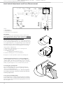
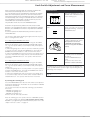
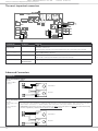
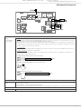
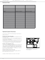
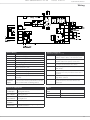
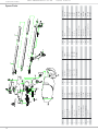
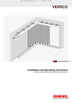
www.samsondoors.co.uk
01933 274276
Installation Instructions
for the garage door operators
TS 75
TS 100
English
www.samsondoors.co.uk
01933 274276
Content
Information and Remarks
Directives and Regulations
Use of the operators
Garage Doors
The installers declaration of conformity
Older Garage Doors
Important Information for the Installer 3
Instruction for the users
Security Advises for the Installation 4
Installation
Different Conditions for Installation 5
Minimum space above the garage door
Door Arm Extension
C-Rail Extension
Bow Arm Conversion
Pre-Mounting the operator 6
Installing the operator 7
The Emergency Release 8
When there is a second entrance to the garage
When the garage door is the only entrance
Printed Circuit Board: Adjustments and Connections
Devices for Adjustments 9
TEST/RUN-Button (1)
LERN/LEARN-Button (2)
Potentiometer “PRESSURE OPEN/CLOSE“ (3)
Potentiometer “LIGHT“ (4)
Limit-Switch Adjustment and Force Measurement 10
Information
1.) Adjusting the maximum force for the learning-cycle
2.) Starting the learning-mode
3.) The Limit Switch Adjustment
4.) Starting the learning cycle
Quick Reference
The most important connectors 12
Push Button and Key Switch
24V DC Supply
230V AC Supply
Receiver-Module
Advanced Connectors 12
Photo-Cell without selftest:
Photo-Cell with selftest
Security Beam and Hatch Door
Modules for Special Functions
Cycle Counter
LED-Lamps 14
LED “TEST“
LED “Diag“
LED “Vp“
LED “SLZ“
LED “LSZ“
LED “SEZ“
LED “SEA“
Special Functions 15
DIP-Switch Settings
Automatic Force Measurement
Additional Force
Pre-Warning light before every movement
Full reversion in OPENING direction
No reversion on Security-Beam when door closed
Side Hinged Doors
2
Remote Control
Programming the Hand Transmitters 16
Basics
Programming Transmitter and Receiver
Clearing the receivers‘ memory
Additional Information 17
Criterias influencing the range
Use with a HomeLink© System
Technical Information
Technical Data
18
Optional Special Functions 18
Module “Automatic Closing“ (AZ)
Module “Separated Impulse“ (TO)
Module “One Way Traffic Control“ (EI)
Wiring 19
Internal Wiring
External connections
Spare Parts 20
Troubleshooting
Troubleshooting 21
Error Messages
Error messages via the operator‘s light
If... then...
Additional messages only via the LED “Diag“
Declaration of Conformity
www.samsondoors.co.uk
01933 274276
Information and Remarks
Important Information for the Installer
It is within legal regulation and without restriction, to use a
Seip door operator with any garage door that has been approved for use with other certified door operators!
Directives and Regulations
The operators TS 75 and TS 100 comply to the latest European directives and regulations. The declaration of conformity is enclosed
at the end of these instructions.
Use of the operators
The operators were designed for the use with up-and-over doors
(tilting and canopy-type) and sectional doors. They can be used
with side-hinged doors using a special conversion-kit.
All garage doors need to be maintained before automation. The
door must be easily opened and closed by hand. A garage door
must not be automated unless it is easy to open and close manually.
Garage Doors
In January 2001 the European regulations EN12604 and EN12605
became compulsory for garage doors. Before installing an automatic door operator it must be assured that the garage doors
applies to these regulations (the information can be obtained from
the manufacturers‘ declaration of confirmity). A Seip door operator may be installed to any door that complies to the regulations.
Should a garage door not be compliant then please refer to the
chapter „older garage doors“.
If, however, the dangers cannot be avoided we recommend to use
the automatic pre-warning function of the operator. The operators‘ lighting will then be blinking for approx. 5 sec. before every
movement of the garage door. People inside the garage will be
warned before the opening and can step back from the garage
door in time.
Instruction for the users
Please instruct the users as follows:
- Use of the hand transmitter
- Use of the emergency release in case of a power failure
- Hand over the separate „User Manual“ to the customer
- Inform the user about the Security Advises in the User Manual
The installers declaration of conformity
No matter whether a door operator was delivered together with a
garage door or seperately, the installer must issue a declaration of
conformity for the complete installation.
With this declaration the installer assures, that the installation
was made according to the instructions given by the manufacturers (e.g. the installation instructions of the garage door and the
operator). This declaration can only be issued by the installer and
may not be issued from the manufacturer!
If both components comply to the directives and the installation
was made as to the manufacturers instructions the whole installation will normally be CE-compliant.
Older Garage Doors
When automating an older garage-door the TS-series will still
comply to the regulations - through the automatic force setting
the requested values for forces and reversion will be according to
the regulations.
But it needs to be taken in consideration that most older garage
doors do not meet the regulations EN 12604 and EN 12605
- especially regarding security features. They might still have sharp
edges bearing the danger of severe injuries - for example sectional
doors might not have a finger protection between the sections.
Unfortunately the entire regulations do not mention how to
handle the automation of such an older garage door - the danger
basically is not the automation but the construction of the door.
Therefore we strongly recommend to
- check the garage door for sharp edges bearing danger when the
door is moving; take any necessary action to avoid the dangers
and make the door safer
- check the doors‘ springs and readjust them if necessary
- grease or oil the pivotal points and rollers of the garage door
- check that the door may be easily used by hand
3
www.samsondoors.co.uk
Information and Remarks
Security Advises for the Installation
Important Safety Instructions for Installation
WARNING: INCORRECT INSTALLATION CAN LEAD TO SEVERE
INJURY
Follow all Installation Instructions.
- Read page 3 of this instruction carefully before the installation
- Before installing the drive, remove unnecessary ropes from the
existing installation
- Maintain the garage door according to the advises on page 3
and to the door manufacturer’s manual
- If possible, install the drive at a height of at least 2,10 m and the
manual release at a height less than 1,80 m
- Locate the push-button within sight of the door but away from
moving parts and at a minimum height of 1,50 m
- Fix the label warning against entrapment next to the push-button
- The label fixed to the manual release may not be removed
- After installation, ensure that the mechanism is properly adjusted
and that the drive reverses when the door contacts a 40 mm high
object placed on the floor.
4
01933 274276
www.samsondoors.co.uk
01933 274276
Installation
Different Conditions for Installation
Minimum space above the garage door
Before installing the operator you should check the garage for the
conditions of installation. You will need optional extras in either of
the following situations:
35mm Minimum
C-Rail Extension
Bow Arm Conversion
Door Arm Extension
If the garage door is higher than 2.250 mm you will need a c-rail
extension. Two sizes of extensions are available: 500mm and
1.000 mmm.
The operator may be extended by a maximum of 1.500mm - the
maximum height of a garage door is 4.150mm.
For a canopy type garage door (inside turning door) you will need
a bow arm conversion to automate the door.
Inside turning doors are equipped with a roler on each side at the
bottom of the door. With these rollers the door cannot tilt outside
- an automation without the bow arm conversion is not possible.
Should the minimum space between the garage door and the ceiling be smaller than 35mm then a door arm extension is needed.
For an extension you can use a metal beam from any DIY-market.
The beam should not be shorter than the door‘s height.
5
www.samsondoors.co.uk
01933 274276
Installation
Pre-Mounting the operator
During this procedure be careful not to twist the chain. Therefore
do not lift the parts - slide them along the floor.
1. The operator is laying unpacked in front of you. The motorhead unit is on your right hand side.
(1)
2. Lay part (1) to the front.
3. Fix through pushing the C-profile coupling piece (2) over it all
the way home.
(3)
4. Slide C-rail part (3) in front of part (1)
5. Set part (3) in the C-rail coupling piece (4) at an angle, inserting
it from above as shown.
(2)
(1)
6. Press down part (3) to tension the chain.
7. Turn around the operator and screw in the milled nuts into the
C-rail coupling pieces.
Your operator now is readily premounted for installation.
The chain has been pretensioned in the factory; do not change
the chain tension!
ATTENTION:
The setting of the limit-switches and the automatic-force
adjustment were set for factory testings. When you change
the limit-switch settings you first have to run a new learning cycle to make the operator work properly! (Please refer to
the pages 10+11)
6
(3)
(4)
www.samsondoors.co.uk
01933 274276
Installation
Installing the operator
(1)
Meassure the distance between the ceiling and the highest point
reached by the garage door (1).
The minimum-headroom necessary for mounting the operator is
35 mm. If there is less headroom please pay attention to page 5.
The front fixing angle can be mounted either at the lintel or at the
ceiling.
(2)
1. Meassure the middle of your garage door and make a mark on
the lintel and the top of your door (2+2a).
2. Fix the front fixing angle in the middle either at the lintel or at
the ceiling. (We recommend the lintel if possible) (2+2a).
3. Attach the C-rail to the front fixing angle (3). Put a carton piece
under the motor head unit to avoid damages.
(2a)
4. To fix the motor head to the ceiling we recommend you to use
a ladder (4). When the operator is laying on the ladder you can
open the garage-door. Adjust the C-rail according to the mark you
made in the middle of the garage-door.
Fix the operator to the ceiling when you have made sure the C-rail
is running straight to the front.
(3)
5. Now fix the door arm to the garage door (5). Take care that the
angle between the operator and the door arm does not exceed a
max. of 45° (it may be lower).
(3a)
6. Before running the operator disengage the door‘s locking-bolts otherwise the operator cannot open the door. This
could result in damage to the operator and/or the garage
door. The self-locking gear of the operator will ensure that the
door cannot be opened manually. If you require additional security, ie using door bolts, please ask your dealer for our locking set,
which is available as an optional extra.
(4)
(5)
(6)
7
www.samsondoors.co.uk
Installation
The Emergency Release
In case of a power failure the garage door can be opened by
hand. Therefore the operator first needs to be released.
Pic. 1
When the garage door is the only entrance
It is necessary to connect the emergency release to the door‘s
handle (pic. 1) otherwise the garage cannot be accessed in a
power failure situation.
Procede as follows:
1. Find out in which direction the door handle moves when opening the door.
2. Drill a hole in that side of the door handle which turns downwards.
3. Thread the cable through the hole and fix it with the enclosed
metal-clamps. Be carefull not to put a high tension on the emergency release cable - the operator then might release from the
garage-door during a normal opening cycle.
4. Check the function of the emergency release together with a
second person. Stay inside the garage and close the door with
the operator. Let the second person open the door manually with
the door keys. If this works, the emergency-release is mounted
properly.
Do not leave the garage and close the garage-door with the
operator before you have tested the emergency-release!
When there is a second entrance to the garage
You can use the supplied handle for the emergency release (pic.
2).
Thread the emergency release cable through the handle.
Fix the metal clamps to the cable where the handle shall be
placed.
Shorten the cable below the metal clamps - the handle is now being held by the clamps.
In case of a power failure the user can now open the garage
door by releasing the operator with the handle for the emergency
release.
8
Pic. 2
01933 274276
www.samsondoors.co.uk
01933 274276
Printed Circuit Board: Adjustments and Connections
Devices for Adjustments
4
3
2
1
This page only shows the functions of the buttons and potentiometers on the P.C.B.. To programme the operator please refer to page 10 onwards.
TEST/RUN-Button (1)
With this button you put the operator into operation. The button
works on the OPEN-STOP-CLOSE principle, e.g. the first push
opens the door, the second push stops the door and the third
push closes the door etc.
The LED-lamp “TEST“ is switched on as long as you press the
TEST-button and shows that the impulse was received an recognised by the electronics.
LERN/LEARN-Button (2)
This button has to functions:
Potentiometer “PRESSURE OPEN/CLOSE“ (3)
With these potentiometers you must adjust the maximum force
for the force learning cycle (please refer to the chapter “Automatic Force Setting“) separately for OPENING and CLOSING direction.
The operator will never override the adjusted forces, neither during the learning cycle nor in later use!
The maximum forces are shown in %. Dependant on the operator
model this means:
max.force
%age
Operator with
75 kg max.
Operator with
100 kg max.
1. Learning the forces
2. Registering (learning) a hand-transmitter
20%
15 kg approx.
20 kg approx.
50%
37 kg approx.
50 kg approx.
The LERN/LEARN-button must be pressed for approx. 3 sec.; the
button can be released once the operator‘s light starts blinking.
Whilst the operator‘s light is blinking you can either register a new
hand-transmitter by pushing the hand transmitters button O R
you may start the learning of forces by pressing the button once
again.
Details on both procedures can be obtained from the chapters
“Automatic Force Setting“ and “Remote Control“.
70%
52 kg approx.
70 kg approx.
100%
75 kg
100 kg
Potentiometer “LIGHT“ (4)
With this potentiometer the time for the internal lighting is adjusted in seconds. Values from 80 to 240 seconds are adjustable.
9
www.samsondoors.co.uk
01933 274276
Printed Circuit Board: Adjustments and Connections
Limit-Switch Adjustment and Force Measurement
3
Pictures:
1: TEST/RUN-Button
2: LERN/LEARN-Button
3: Potentiometer for Force Adjustment
Information
To use the operator the following steps must be carried out to
adjust the limit-switches and to learn the required force. Without
these adjustments the operator will only run for the factory
set distance when pressing the TEST-button.
The limit-switch adjustment and the force-learning are both done
in one combined programming step. The operator needs to be set
into programming-mode - the programming-mode is indicated by
the blinking operator’s light. During the programming-mode the
limit-switch setting is done first, followed by the force-setting.
The procedure of adjustments:
1.) Adjustment of the maximum force for learning-mode
2.) Start of programming-mode
3.) OPENING limit-switch
b.) Adjustment CLOSING limit-switch
4.) Start the learning-cycle for force and distance.
Descriptions of each step will be found in the following text.
1.) Adjusting the maximum force for the learning-cycle
The force adjusted via the potentiometers “FORCE OPEN“ and
“FORCE CLOSE“ determines the maximum forces for the learning cycle and in later use. The factory setting is 60% for both. On
smaller, easy running doors a force of 40% will be sufficient.
2.) Starting the learning-mode
Press the LERN/LEARN button (2) on the main electronics for
approx. 3 seconds. When the operator’s light begins blinking
- release the LERN/LEARN button.
The operator now runs in learning-mode. The learning-mode
runs without time-limit - there is no need to rush with the
following adjustments.
3.) The Limit Switch Adjustment
In CLOSING-position the garage door shall not be pressed hard
onto the doors‘ frame. If it is pressed too hard then the operator
will reverse after each CLOSING and the garage door will remain
open for approx. 5 cm.
10
2
1
www.samsondoors.co.uk
01933 274276
Printed Circuit Board: Adjustments and Connections
Limit-Switch Adjustment and Force Measurement
Basics: During the learning-mode the operator will follow the
limit-switches automatically when these are moved.
E.g.: The operator hits the CLOSING limit-switch but the garagedoor still is not completely closed. You can now slide the red
limit-switch actuator off the CLOSING limit-switch - the operator
will automatically start running in CLOSING direction until it hits
the CLOSING limit-switch again. You do not have to press the
TEST/RUN button to activate the operator.
The procedure works vice-verca in OPENING direction.
Attention: the operator only follows the limit-switch in ONE
direction - the CLOSING limit-switch is only followed in CLOSING
direction, the OPENING limit-switch is only followed in OPENING
direction.
To run the operator in another direction you have to press the
TEST/RUN button.
The operator’s light will be blinking throughout the whole procedure of setting the limit switch.
3.)a.) Adjusting the OPENING limit switch
1.) Run the operator in OPENING direction using the TEST/RUN
button (1) (the button follows the principle OPEN-STOP-CLOSE
etc., e.g. first impulse OPEN, second impulse STOP, third impulse
CLOSE etc.)
2.) When the garage door is almost opened to maximum you have
to stop the operator using the TEST/RUN button. Then slide the
OPENING limit switch actuator so that it hits the limit-switch.
3.) When the OPENING limit switch is hit before the garage door is
opened to maximum then simply slide the red limit switch actuator further in OPENING direction - the operator will follow the
movement.
3.)a.) Adjusting the CLOSING limit-switch
1.) Run the operator in CLOSING direction using the TEST/RUN
button (1) (the button follows the principle OPEN-STOP-CLOSE
etc., e.g. first impulse OPEN, second impulse STOP, third impulse
CLOSE etc.)
2.) When the garage door is closed you have to stop the operator
using the TEST/RUN button. Then slide the OPENING limit switch
actuator so that it hits the limit switch.
3.) When the CLOSING limit switch is hit before the garage door
is closed then simply slide the red limit switch actuator further in
CLOSING direction - the operator will follow the movement.
Quick Reference
1.) Force Adjustment
Adjust the maximum force for
OPENING and CLOSING direction
for the learning cycle
2.) Start programming
mode
Press the LERN/LEARN button for
approx. 3 seconds. The operator’s
light begins blinking - release the
LERN/LEARN button
3.) Limit Switch Adjustment
a.) Adjust OPENING limit switch
b.) Adjust CLOSING limit switch
(The operator can be run
in OPENING and CLOSING
direction using the TEST/RUN
button)
4.) Start learning cycle
The garage door is closed and
the operators hits the CLOSING
limit switch
Press the LERN/LEARN button
shortly
The operator does three runs
(OPENING-CLOSING-OPENING)
The learning cycle stops after the three runs. The garage door
is then opened and the operator’s light stops blinking. The programming is now complete.
5.) You may now procede with chapter “Remote Control“ on
page 16
4.) Starting the learning cycle
Press the LERN/LEARN button after the limit switches are adjusted
properly (the garage-door should then be closed and the CLOSING
limit-switch is actuated).
The operator then starts the automatic learning cycle and will do
three runs:
- OPENING the garage door
- CLOSING the garage door
- OPENING the garage door.
All three runs are done fully automatic.
After the learning cycle the operator will rest in OPENING position
- the operator’s light stops blinking. The operator now is ready
for use. For programming the hand-transmitter please refer to the
chapter “Remote-Control“ on page 16.
11
www.samsondoors.co.uk
01933 274276
Printed Circuit Board: Adjustments and Connections
The most important connectors
Component
Connector
Function
Push Button and
Key Switch
A+B
Floating connector for push button and key switch:no electricity to come into contact
with these connectors!
When using an external receiver the impulse wires are connected to this terminal.
24V DC Supply
G+H
24V DC power supply for external components (external receiver, photo-cell), a maximum of 200 mAmp. is allowed.
230V AC Supply
M+N
230V AC power supply for external components. Shortcuts created by external components on this connector will influence the house fuse directly.
Receiver-Module
HF-Modul /
Receiver-Card
Plug for Seip remote-receiver cards.
Advanced Connectors
Component
Photo-Cell without selftest:
C+D
(with 8,2 kOhm
resistor)
Wiring:
�
�
�
�
�� �
�� �
�
�
��� �W
Transmitter
Receiver
����
Photo-Cell with selftest
C+D
(Photo-Cell receiver)
I+J
(Photo-Cell transmitter)
The main electronics provides the possibility of testing the photo-cell before every movement - within milliseconds a malfunction of the photo-cell is simulated. To enable the main-electronics for this testing the impulse cables of the photo-cells‘ transmitter must be connected to I + J and the impulse cables of the photo-cell’s receiver must be connected to C + D.
ATTENTION! If you want to use this selftest option, you must connect the photo-cell before the limit switch setting
and force adjustment, otherwise there will be no selftest in later use.
�
�
�
�
�� �
Transmitter
�� �
�
�
12
��� �W
����
Receiver
www.samsondoors.co.uk
01933 274276
Printed Circuit Board: Adjustments and Connections
Advanced Connectors
Security Beam and Hatch Door
E+F
(mit 8,2 kOhm
Auswertung)
Function
OPENING direction: when releasing the CLOSING limit-switch the connector is checked for 3 seconds (= hatch door closed or
opened). Impulses coming in later during the OPENING cycle will be ignored.
CLOSING direction: the connector is being checked throughout the whole CLOSING cycle. If an obstacle is recognized (by the
security-beam) the operator will reverse (please also refer to chapter “Special Functions“, paragraph “DIP-Switch 4“, page 15).
Two devices may be connected to this connector:
1.) Security-Beam
This device is normally equipped with a 8.2 kOhm resistor. Therefore you have to remove the 8.2 kOhm resistor from the connectors E + F before connecting the security-beam.
2.) Hatch-Door Switch
A hatch-door within the garage door can be secured with a switch - when the switch is not activated (e.g. the hatch-door
stands open) the operator will not work.
Security Beam (8,2 kOhm resistor connected in line):
�
�
��� �W
Hatch-Door Switch (8,2 kOhm resistor connected in line):
��� �W
�
�
Security Beam and Hatch-Door (connected in line):
�
�
��� �W
Modules for Special Functions
„Versions Module“
Plug for optional modules providing special functions:
- Automatic Closing (AZ)
- One-Way traffic control (EI) with traffic-light regulation
- Dead-Man-Function (TO) (push-button needs to be pressed during the whole CLOSING cycle, otherwise the operator stops)
Cycle Counter
L
A counter for OPENING/CLOSING cycles can be connected (24V)
13
www.samsondoors.co.uk
01933 274276
Printed Circuit Board: Adjustments and Connections
LED-Lamps
LED
Function
ON
OFF
LED “TEST“
“ON“ when a device connected to A+B (push-button, key-switch)
or the electronics‘ TEST-button gives an impulse
Incoming impulse
No incoming impulse
LED “Diag“
“ON“ when an impulse from a programmed hand-transmitter is
received.
More functions of this LED are named in the chapters “Learning
the force“, “Remote-Control“ and “Error messages“.
Incoming impulse
from a programmed
hand-transmitter
No incoming impulse from a handtransmitter
LED “Vp“
“ON“ when mains power supply is o.k.
Mains power supply
o.k.
No mains power
LED “SLZ“
Photo-Cell
Possible Errors:
- an obstacle is registered by the photo-cell
- the connection wires might be broken or a short-cut was created
- the photo cell is damaged
- the 8.2 kOhm resistor is not connected properly
Error or obstacle
o.k.
LED “LSZ“
Security Contact / Hatch-Door Switch
Possible Errors:
- the security beam registers an obstacle
- the hatch-door is open
- the connection wires might be broken or a short-cut was created
- Security beam or hatch-door switch is damaged
- the 8.2 kOhm resistor is not connected properly
Error or obstacle
o.k.
LED “SEZ“
Checks the function of the CLOSING limit switch - when the limit
switch is activated, the LED goes on. If it does not, then the limit
switch is damaged.
activated
not activated
LED “SEA“
Checks the function of the OPENING limit switch - when the limit
switch is activated, the LED goes on. If it does not, then the limit
switch is damaged.
activated
not activated
14
www.samsondoors.co.uk
01933 274276
Printed Circuit Board: Adjustments and Connections
Special Functions
1 2 3 4 5 6
DIP
DIP-Switch Settings
DIP-Switch
1
Function
Automatic Force Measurement
ON
OFF
Yes
No
Yes
No
Yes
No
Yes
No
Yes
No
Yes
No
Standard setting: ON
ATTENTION! In countries of the European Union the operator must be run with automatic
force measurement - running it on manual force is illegal!
In non-European countries the manual force may be used. Please pay attention to the fact, that the
learning cycles (chapter “Limit-Switch Settings and Force Adjustment“, pages 10+11) must also be done
when manual force is chosen!
2
Additional Force
Standard setting: ON
For very light garage doors we recommend to set the switch to OFF
3
Pre-Warning light before every movement
Standard setting: OFF
When choosing ON a pre-warning of appox. 4 sec. will be made before each movement of the garage
door.
4
Full reversion in OPENING direction
Standard setting: ON
The operator reverses approx. 20 cm when an obstacle in CLOSING direction is recognised. If the switch
is set to ON the operator will reverse completely in OPENING direction until the OPENING limit switch is
reached.
5
No reversion on Security-Beam when door closed
Standard setting: ON
This function is only needed when a security-beam is connected. In garages with an uneven floor the
security-beam might lead to unwanted reversion when the garage door is almost closed. If the switch is
set to ON the revertion in SOFT-STOP will be prevented - the operator simply stops and the door remains
closed.
HINT! Using this function might lead to problems programming new hand-transmitters via an existing
hand-transmitter. For that programming the operator needs to hit the CLOSING limit-switch. Please also
refer to chapter “Remote Control“
6
Side Hinged Doors
Standard setting: OFF
For use with a side hinged door the OPENING and CLOSING directions need to be reversed - setting this
switch to ON will do that automatically.
15
www.samsondoors.co.uk
01933 274276
Remote Control
Programming the Hand Transmitters
Basics
As a standard the operator is equipped with a 433 MHz AM
remote control set. The coding is done via rolling code - the code
is changed after each impulse; receiver and transmitter agree completely automatic about the next code to be used. New codes will
be chosen out of a pool of billions of possible codes.
Quick reference: programming the first hand transmitter
1.) Keep the LERN/LEARN
button pressed for approx.
3 sec.
��������
The operators‘ light will start
blinking
����������
Your operator is equipped with our standard remote control set
when you hand transmitters looks like the one shown on the right
hand side. The 4-channel MIDI transmitter is standard equipment,
the 2-channel MINI transmitter is available as an optional.
If your operator is equipped with another remote control set,
please refer to the manufacturers instructions for programming.
2.) Press the hand transmitter button you want to use
The operators‘ light stops
blinking - the transmitter was
succesfully programmed
Programming Transmitter and Receiver
To use a hand transmitter it must first be registered (programmed)
by the receiver. Only one hand transmitter button can be used for
one receiver.
Registering the first hand transmitter
The first hand transmitter (e.g. no hand transmitter has been
registered for the receiver, yet) must be learned directly via the
operators‘ main electronic:
1. Press the LERN/LEARN button on the main electronic for approx.
3 seconds until the operator’s light starts blinking and release the
LERN/LEARN button.
2. Press the hand transmitter button you want to register to the
receiver - the operators’ light stops blinking when the transmitters’ signal was received. The transmitter is now registered.
Registering additional hand transmitters
When at least one hand transmitter has been registered by the
receiver you may program additional hand transmitters from a
distance:
1. The garage door must be closed
Quick reference: Programming additional hand transmitters from a distance
Remark: additional hand transmitters can be programmed
either like the first transmitter or from a distance as explained
below:
1.) Open the garage door
for approx. 50 cm and close
it again
After the garage door is closed
you have got 10 seconds to proceede to step 2)
2.) Press buttons 1+2
simultaneousely on any
registered transmitter for
3 sec.
The operators‘ begins blinking
- release the hand transmitters‘
buttons
3.) Take the new hand
transmitter and press the
button you want to use
shortly
The operators‘ light stops
blinking - the hand transmitter
was successfully programmed
2. Open the garage door approx. 50 cm and close it again.
3. After the garage door is closed you have got 10 seconds to
press the buttons 1+2 simultaneously on the registered hand
transmitter - the operator’s light then starts blinking.
4. The light will keep blinking for another 10 seconds - during that
period of time you must press the button on the new hand transmitter which you want to use with the operator. Once the new
transmitter is registered the operator’s light stops blinking.
The procedure must be repeated for each new hand transmitter.
Clearing the receivers‘ memory
Keep the LERN/LEARN button pressed for approx. 15 sec.. The
operators‘ light and the red LED „Diag“ will start blinking after 3
seconds. After another 10 seconds the red LED „DIAG“ will glow
constantly. You can then release the LERN/LEARN button.
All previousely programmed hand transmitters are now
cleared from the receivers‘ memory.
16
www.samsondoors.co.uk
01933 274276
Remote Control
Additional Information
4-channel MIDI transmitter,
433 MHz, rolling code
3
2-channel MINI transmitter (optional extra),
433 MHz, rolling code
4
2
1
Two Batteries
Battery
Usable types of batteries: A23, 23A, 23L, EL12, VR 22 and
MN 21
Voltage: 12V
Used batteries must be disposed according to national
laws!
Two batteries, type CR1616 or DL1616 are required.
Voltage: 2* 3V (=6V)
Used batteries must be disposed according to national
laws!
Criterias influencing the range
Use with a HomeLink© System
The TS operators are equipped with a high quality remote
control set as a standard!
The HomeLink© System is becoming more and more popular in
private households. Most frequently it is being used in cars - the
HomeLink© module is integrated in the car. It allows the driver to
activate the door operator with a push of button which is installed
in his car. Once programmed, the driver does not need the hand
transmitter to access the garage with his car.
Nevertheless the remote control is the part of the operator which
might be influenced by circumstances in the surroundings of the
garage. With our standard remote control you might reach a
range of more than 100 meters. In areas with high disturbancies
the range will still be approx. 50 meters.
The range might be influenced by:
- old batteries in the hand transmitter - if you should experience
a problem with the range, please change the batteries first. The
lower the batteries run the lower the range will be.
- Building materials of the garage
In a garage made of concrete and steel you might reach a lower
range than in an ordinary garage build of stone. The more steel
was used for the walls the shorter the range of your remote-control.
Remote-control activity in the area
Radio and television transmitters close to your garage might
reduce the range.
The standard remote control supplied with the TS-series is compatible with HomeLink© systems manufactured by end of year
2002 / beginning of year 2003 (subject to technical alterations).
The procedure how to program the HomeLink© device is described in the car‘s manual - please refer to those instructions.
(Basic information on programming: you first must register
the hand transmitter with the operator. The HomeLink©
system will then learn the code from the hand transmitter).
Please avoid to drop the hand transmitter - parts could
be damaged inside the transmitter. That might lead to
malfunctions!
Older baby-phones
Especially older baby-phones might influence the range of the
remote control severely. These devices send strong signals via the
houses internal power supply net. These signals also intrude other
devices via the wall plug, as eg the operator.
It is extreemely unlikely that the range will drop to an unacceptable distance. If, however, problems should occure we will like to
be helpful.
17
www.samsondoors.co.uk
01933 274276
Technical Information
Technical Data
TS 75
TS 100
Maximum Pulling Force (adjustable)
70 kg (+/- 4%)
100 kg (+/- 4%)
Force-Setting for Operation
automatic
automatic
Motor
24V DC, low-noise
24 V DC, low-noise
Running Speed
14,5 cm/sec.
14,5 cm/sec.
Speed in Soft Mode
8 cm/sec.
8 cm/sec.
Lighting
230V AC, max. 40 watts
230V AC, max. 40 watts
Lighting Durance (adjustable)
80 to 240 seconds
80 to 240 seconds
Duty Cycle
80%
80%
Power Consumption in Stand By
2,3 watts
2,3 watts
Power Supply
190-250V AC
190-250V AC
Transformer
230V AC, 24V DC
230V AC, 24V DC
Pre-Warning Light
adjustable
adjustable
Stop on Security Beam in Closing Direction
adjustable
adjustable
Automation of Side Hinged Doors
adjustable
adjustable
Nett Running Length
2.640 mm
2.640 mm
Max. Running Length with Extension
4.150 mm
4.150 mm
Overall Length
3.215 mm
3.215 mm
Height Motor Head
170 mm
170 mm
Length Motor Head
370 mm
370 mm
Width Motor Head
260 mm
260 mm
Minimum Space above the door
35 mm
35 mm
Weight including packaging
22 kg
Optional Special Functions
For the TS-series operators we provide plug-on module cards for
advanced functions:
Module “Automatic Closing“ (AZ)
For automatic closing of the garage after an adjustable time from
80 to 240 seconds.
The card is also equipped with a connector giving an impulse for
one second when the garage door is opened - an automatic external light can be connected here.
Special functions as “fast closing“ (the garage door will be closed
as soon as the car passed the photo cell) and “additional photocell in opening direction“ are adjustable on the module-card.
Module “Separated Impulse“ (TO)
The impulses for OPENING and CLOSING direction are given separetely - one button will always OPEN the door and the other will
allways CLOSE it. It can be adjusted so either direction will work
on impulse or steady press of the button (e.g. the button needs to
be pressed for the whole OPENING or CLOSING cycle - when the
button is released the door stops)
Module “One Way Traffic Control“ (EI)
A traffic control for narrow access to/from a garage. Red and
green traffic lights can be connected.
Installation and User manuals are enclosed to the modules.
18
Sample: Modul for automatic closing
with potentiometer for adjustment of
the opening time.
www.samsondoors.co.uk
01933 274276
Technichal Information
Wiring
� �����
�
�
�
�
�
�
�
�
�
�
�
�
�
�
�
�
�
�
�
�
�
�
Internal Wiring
1
Blue, mains supply, 230V
2
Brown, mains supply, 230V
3
Black, transformer, 230V
4
Black, transformer, 230V
5
Brown, Lighting, 230V
6
Blue, Lighting, 230V
7
White, transformer, 24V
8
White, transformer, 24V
9 MOTOR
Connector for the plug from the motor
K
Connector for the plug from the limit switches
PE
Earthing of
the mains
supply
External connections
(Explained on pages 12 + 13)
A+B
Floating connector for push-button, key-switch
and the impulse cables of an external receiver
C+D
Floating connector with a 8,2kOhm resistor for
impulse cables from a photo-cell receiver
E+F
Floating connector with a 8,2 kOhm resistor for
security beam and hatch-door switch
G+H
24V DC supply for external components (max.
200 mAmp.)
I+J
24V DC for a photo cell transmitter when a
self test before every movement of the door is
required
Earthing from the printed circuit board to the
base plate
L
Connector for a cycle counter (24V) - all openings will be counted
The earthing of the mains supply (green/yellow)
is connected to the base plate with a screw (the
screw is marked with a earthing symbol)
M+N
230V AC for external components - not secured
by the electronics. Shortcuts will blow the
house fuse.
Devices for adjustments
Other
Potentiometer
„Licht/Light“
Adjustment of the time for the internal
lighting (60-240 Sek)
HF-Modul/Receiver Plug for receiver module, 433 MHz
Card
Potentiometer
„Force Open“
Adjustment of the maximum force for the
opening direction
Versions-Modul
Plug for modules for special functions
Potentiometer
„Force Close“
Adjustment of the maximum force for the
closing direction
FUSE
Fuse T1,6, 250V
Button
„Test/Run“
Runs the operator - OPEN-STOP-CLOSE
Button
„Lern/Learn“
For automatic force setting and registration
of hand transmitters
19
20
Printed Circuit Board
Lampholder
Light Bulb
Power Supply Cable
Limit Switch Unit
Limit Switch Actuator
Spur Toothed Wheel
Step Wheel
Cover
3
4
5
6
7
8
9
10
12
PI0006
PI0105
PH3201
PI1200
PH0830
PJ0450
PJ0530
PH2101-1
PE05004
PL2006
PL1312
Transformer
Motor TS 100
2
PL1212
Stock-Code
9
Motor TS 75
8
Description
3
1
12
16
7
10
17
1
8
18
17
16
15
13
No.
5
4
20
C-Shaped Part
Pinion TS 100
Pinion TS 75
Twisted Nipple
Threaded Distance Piece
Light Cover
Description
13
2
21
28
19
30
24
22
PH1500
PM11005
PM11006
PI1311
PI0310
PI0005
Stock-Code
23
31
PM1400
PH3000
Door Arm
Bowden Cable
Guide Pulley Holder
Guide Pulley
Fixing Square
Chain Guide Block
C-Profile Coupling Piece
C-Rail, 1m
23
24
25
26
27
28
29
PI0502
PM04003
PI0120
PM12002
M07000
PH2403
PH2600
Carriage
22
PH2200
PM0310
Chain Tensioner
Chain Closing Link
20
PM0301
Stock-Code
Chain
28
Description
25
19
27
26
No.
29
www.samsondoors.co.uk
No.
15
6
18
Technical Information
01933 274276
Spare Parts
www.samsondoors.co.uk
01933 274276
Troubleshooting
Troubleshooting
Error Messages
The TS-series is equipped with a system of error messages via the
internal lighting and the LED “Diag“.
Error messages via the operator‘s light
2 x blinking
Limit switch error - either one of the limit switches is damaged
or the relays on electronic board are damaged.
5 x blinking
Neither the OPENING limit switch nor the CLOSING limit switch
were reached. The operator is switched off. Check the limit
switch settings and start a new learning cycle.
8 x blinking
The microprocessor has lost data - try to run the learning
cycle. When this does not work, the electronics need to be
exchanged.
Additional messages only via the LED “Diag“
3 x blinking
Photo cell - either an obstacle was recognised by the photo cell
or the photo cell is damaged. Please also check the photo cells
wiring.
4 x blinking (only with special function module “AZ“ running in
French mode)
Photo cell for opening direction - either an obstacle was recognized by the photo cell or the photo cell is damaged. Please also
check the photo cells wiring.
6 x blinking
9 x blinking
Photo Cell - either an obstacle is within the photo cell’s range or
the photo cell does not work properly.
Error on the electronic board - the electronics need to be exchanged.
7 x blinking
10 x blinking
Security Beam or Hatch Door Switch - either an obstacle is inbetween the devices or the device does not work properly
Damaged relays - the electronics need to be exchanged
11 x blinking
Error on a module for special functions - change the module. If
the error still occures the main electronics must be exchanged.
If... then...
The operator does not react on the transmitter or on the push-button switch
Power failure? Disconnect and connect the operator. Is the door stuck
because of snow and ice? Check the lines and the connections of the
push-button switch. Is there water in the push-button switch or in the key
operated switch? Disconnect alle external components and try running the
operator via the TEST/RUN button.
The operator reacts on the transmitter but not on the push-button
switch
Check the line of the push-button switch. Does the push-button switch
work, when the remote receiver is disconnected? If so, the remote transmitter or receiver might be defective.
The operator reacts on the push-button switch but not on the
transmitter
Check the accordance of the transmitter and the receiver code. Displace
the antenna of the receiver. Avoid each metal contact (reduces the range).
Check the battery of the transmitter
The operator reacts on the push-button switch but not on the
transmitter
Change the code of your remote control (of transmitter and receiver). Disconnect the receiver or remove the transmitter battery. Use your push-button switch only. If this solves the problem, your sender may be defective.
Disconnect the push-button switch and use your transmitter only. If this
solves the problem, the push-button switch or the line of the push-button
switch may be defective.
The door doesn’t open completely
Is the limit switch „OPEN” correctly set? Is the door jamming while
opening? Unlock the carriage manually (make the door running well).
Lubrificate and oil the pivotal points of the door. Increase the power.
The door doesn’t close completely and opens again
Is the limit switch „CLOSE” set correctly? Is the door jamming while
closing? Unlock the carriage manually (make the door running well).
Lubricate and oil the pivotal points of the door. Run through the automatic
learning cycle.
The emergency release doesn’t work
Is the limit switch „CLOSE” correctly set? If not, your opener switches off
under pressure. In this case the chain is under tension and therefore the
emergency release can hardly be unlocked. Make sure that the limit switch
is correctly set.
The light doesn’t work
Replace the bulb (230 V, max. 40 Watt)
The operator isn’t running smooth
Unlock the carriage of the opener. Move the door manually and make sure
that the door is well balanced (must come to a stop at each position).
The spring tension is too high or there is even a spring fracture.
The motor is buzzing but the door doesn’t move
The door is jamming.
The operator works, but the door doesn’t move
The carriage is unlocked. If you want to lock it, open the door, but not
completely, and let the opener run. The carriage locks in automatically.
The operator doesn’t work because of a power failure
Unlock the carriage with the help of the emergency release and open
the door manually. (If you have a garage where you can only enter from
outside: Unlock the door with the key and turn the door-handle, then your
opener will be unlocked. If you have a garage where you can also enter
from inside: pull at the Bowden cable hanging from the carriage.)
21
www.samsondoors.co.uk
01933 274276
EG-Konformitätserklärung
EC Declaration of Confirmity
im Sinne der EG-Richtlinien
Niederspannungsrichtlinie 73/23/EWG
mit Änderungen
Elektromagnetische Verträglichkeit 89/336/EWG
mit Änderungen
Low-Voltage Directive 73/23/EEC
and amendments
Electro-Magnetical Compatibility 89/336/EEC
and amendments
Document No. AN-16062003
Dokument Nr. AN-16062003
We,
Wir,
Seip Antriebstechnik GmbH
Grombacher Straße 83, 75045 Walzbachtal-Jöhlingen, Deutschland
hereby declare, that the following products comply to the mentioned EC-regulations.
erklären hiermit, daß die nachfolgenden genannten Produkte den unten angegebenen
EG-Richtlinien entsprechen.
Type of Product / Produktart
Garage Door Operator / Torantrieb
Product Name / Modell
TS 75, TS 100
Approved according to 89/336/EEC and 73/23/EEC / Geprüft nach 89/336/EWG und 73/23/EWG
Referring EC-regulations: / Angewandte harmonisierte Normen:
Electromagnetic Compatibility /
Elektromagnetische Verträglichkeit
EN 61000-3-2:2000
Limits for harmonic current emissions /
Grenzwerte für Oberschwingströme
EN 61000-3-3:1995 + Corrigendum:1997 + A1:2001
Limitation of voltage changes, voltage fluctuations and flicker in publik low-voltage supply systems /
Grenzwerte für Spannungsschwankungen und Flicker
EN 61000-6-3:2001
Emission standard for residential, commercial and light-industrial environments /
Störaussendung für Wohnbereich, Geschäfts- und Gewerbereiche sowie Kleinbetriebe
EN 61000-6-2:2001
Generic standards - Immunity for industrial environments
Fachgrundnorm - Störfestigkeit - Industriebereich
Low-Voltage Directive /
Niederspannungsrichtlinie
EN 60335-2-95:2001-7
Particular requirements for drives for vertically moving garage doors for residential use /
Anforderungen für Antriebe von Garagentoren mit Senkrechtbewegung zur Verwendung im Wohnbereich
EN 60335-1:1994 + A1:1996 + A2:2000 + A11:1995 + A12:1996 + A13:1998 + A14:1998 + A15:2000 +
A16:2001
Safety of household and similar electrical appliances /
Sicherheit elektrischer Geräte für den Hausgebrauch
Safety in Use /
Nutzungssicherheit
EN 12453:2000
Safety in use of power operated doors, requirements /
Nutzungssicherheit kraftbetätigter Tore, Anforderungen
EN 12445:2000
Safety in use of power operated doors, Test methods /
Nutzungssicherheit kraftbetätigter Tore, Prüfverfahren
Peter Seip, Geschäftsführer, Walzbachtal-Jöhlingen, 16.06.2003
GmbH
�������� �������
Grombacher Straße 83
75045 Walzbachtal-Jöhlingen
Germany
www.seip.com
www.samsondoors.co.uk
01933 274276
EG-Konformitätserklärung
EC Declaration of Confirmity
gemäß dem Gesetz über Funkanlagen und Telekomm
unikationsendeinrichtungen (FTEG) und der Richtlinie
1999/5/EG (R&TTE)
in accordance with the Radio and Telecommunications
Terminal Equipment Act (FTEG) and Directive 1999/5/EC
(R&TTE Directive)
Document No. FU-16062003
Dokument Nr. FU-16062003
We,
Wir,
Seip Antriebstechnik GmbH
Grombacher Straße 83, 75045 Walzbachtal-Jöhlingen, Deutschland
declare that the product
erklären, daß das Produkt
SKR 433
Code B43A023004
Hand Transmitter as remote control for garage door operators
Handsender als Fernbedienung für Garagentorantriebe
(Short Range Device)
(Funkgerät geringer Reichweite (SRD))
complies with the essential requirements of §3 and the other relevant provisions of the FTEG (Article 3 of the R&TTE Directive), when
used for its intended purpose.
bei bestimmungsgemäßer Verwendung den grundlegenden Anforderungen des §3 und den übrigen einschlägigen Bestimmungen des
FTEG (Artikel 3 der R&TTE) entspricht.
§3(1)1, (Article 3(1)a)) does not refer to this type of product.
§3(1)1, Artikel 3(1)a) bezieht sich nicht auf diesen Produkttyp, es gibt hierzu keine Norm
Protection requirement concerning electromagnetic compatibility §3(1)(2), (Article 3(1)(b))
Schutzanforderungen in Bezug auf die elektromagnetische Verträglichkeit §3(1)2, Artikel 3(1)b))
EN 300 220-1/1997
EN 300 683/1997
EMV / EMC Directive 89/336/EEC;92/31/EEC;93/68/EEC
Peter Seip, Geschäftsführer, Walzbachtal-Jöhlingen, 16.06.2003
GmbH
�������� �������
Grombacher Straße 83
75045 Walzbachtal-Jöhlingen
Germany
www.seip.com