1
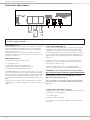
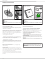
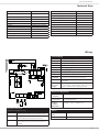
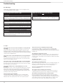
Installation Instructions
for the garage door operator
RP60A
This booklet must be handed over to the end-user
together with the user-manual.
3V1 SKR1W
English
Content
Information and Remarks
Directives and Regulations
Use of the operators
Garage Doors
The installers declaration of conformity
Older Garage Doors
Important Information for the Installer 3
Instruction for the users
Security Advises for the Installation 4
Installation
Different Conditions for Installation 5
Minimum space above the garage door
Door Arm Extension
C-Rail Extension
Pre-Mounting the operator 6
Installing the operator 6
Minimum head room above the door
Adjusting the running-length blocks 8
The Emergency Release 9
When there is a second entrance to the garage
When the garage door is the only entrance
Printed Circuit Board: Adjustments and Connections
Devices for Adjustments 10
TEST/RUN-Button (1)
LERN/LEARN-Button (2)
Jumper “KRAFT/PRESSURE” (3)
Combined TEST + LERN button functions
Programming Running-Length and Force 11
Information
1.) Adjusting the running-length blocks
2.) Starting the programming-mode
3.) Start the learning-cycle
Quick Reference
Special Functions 12
Readjusting the time for the internal light
Setting the pre-warning ON/OFF
Programming the Soft-Modes
The BOTTOM Soft-Stop
Programming the BOTTOM Soft-Mode
Enabling the TOP Soft-Modes
Reducing the Closing Speed
Why reduce the Closing Speed?
When to reduce the Closing Speed?
Programming the Closing Speed
2
External Connections 15
Push Button and Key Switch
Photo-Cell
24V AC Supply
Receiver-Module
LED-Lamps 16
LED “TEST“
LED “Diag“
LED “Vp“
Remote Control
Programming the Hand Transmitters 17
Basics
Programming Transmitter and Receiver
Clearing the receivers‘ memory
Additional Information 18
Criterias influencing the range
Use with a HomeLink© System
Technical Information
Technical Data 19
Wiring 19
External connections
Internal Wiring
Troubleshooting 20
Error Messages
Error messages via the operator‘s light
If... then...
Additional messages only via the LED “Diag“
Information and Remarks
Important Information for the Installer
It is within legal regulation and without restriction, to use a
Seip door operator with any garage door that has been approved for use with other certified door operators!
Directives and Regulations
The garage door operator RP60 complies to the latest European
directives and regulations. The declaration of conformity is enclosed at the end of these instructions.
Use of the operators
The operators were designed for the use with up-and-over doors
(tilting and canopy-type) and sectional doors.
All garage doors need to be maintained before automation. The
door must be easily opened and closed by hand. A garage door
must not be automated unless it is easy to open and close manually.
Garage Doors
In January 2001 the European regulations EN12604 and EN12605
became compulsory for garage doors. Before installing an automatic door operator it must be assured that the garage doors
applies to these regulations (the information can be obtained from
the manufacturers‘ declaration of confirmity). A Seip door operator may be installed to any door that complies to the regulations.
Should a garage door not be compliant then please refer to the
chapter „older garage doors“.
If, however, the dangers cannot be avoided we recommend to use
the automatic pre-warning function of the operator. The operators‘ lighting will then be blinking for approx. 5 sec. before every
movement of the garage door. People inside the garage will be
warned before the opening and can step back from the garage
door in time.
Instruction for the users
Please instruct the users as follows:
- Use of the hand transmitter
- Use of the emergency release in case of a power failure
- Hand over the separate „User Manual“ to the customer
- Inform the user about the Security Advises in the User Manual
The installers declaration of conformity
No matter whether a door operator was delivered together with a
garage door or seperately, the installer must issue a declaration of
conformity for the complete installation.
With this declaration the installer assures, that the installation
was made according to the instructions given by the manufacturers (e.g. the installation instructions of the garage door and the
operator). This declaration can only be issued by the installer and
may not be issued from the manufacturer!
If both components comply to the directives and the installation
was made as to the manufacturers instructions the whole installation will normally be CE-compliant.
Older Garage Doors
When automating an older garage-door the TS-series will still
comply to the regulations - through the automatic force setting
the requested values for forces and reversion will be according to
the regulations.
But it needs to be taken in consideration that most older garage
doors do not meet the regulations EN 12604 and EN 12605
- especially regarding security features. They might still have sharp
edges bearing the danger of severe injuries - for example sectional
doors might not have a finger protection between the sections.
Unfortunately the entire regulations do not mention how to
handle the automation of such an older garage door - the danger
basically is not the automation but the construction of the door.
Therefore we strongly recommend to
- check the garage door for sharp edges bearing danger when the
door is moving; take any necessary action to avoid the dangers
and make the door safer
- check the doors‘ springs and readjust them if necessary
- grease or oil the pivotal points and rollers of the garage door
- check that the door may be easily used by hand
Up-and-over door
sectional door
3
Information and Remarks
Security Advises for the Installation
Important Safety Instructions for Installation
WARNING: INCORRECT INSTALLATION CAN LEAD TO SEVERE
INJURY
Follow all Installation Instructions.
- Read page 3 of this instruction carefully before the installation
- Before installing the drive, remove unnecessary ropes from the
existing installation
- Maintain the garage door according to the advises on page 3
and to the door manufacturer’s manual
- If possible, install the drive at a height of at least 2,10 m and the
manual release at a height less than 1,80 m
- Locate the push-button within sight of the door but away from
moving parts and at a minimum height of 1,50 m
- Fix the label warning against entrapment next to the push-button
- The label fixed to the manual release may not be removed
- After installation, ensure that the mechanism is properly adjusted
and that the drive reverses when the door contacts a 40 mm high
object placed on the floor.
4
Installation
Different Conditions for Installation
Minimum space above the garage door
Before installing the operator you should check the garage for the
conditions of installation. You will need optional extras in either of
the following situations:
35mm Minimum
C-Rail Extension
Door Arm Extension
If the garage door is higher than 2.250 mm you will need a c-rail
extension. Two sizes of extensions are available: 500mm and
1.000 mmm.
The operator may be extended by a maximum of 1.500mm - the
maximum height of a garage door is 4.150mm.
Should the minimum space between the garage door and the ceiling be smaller than 35mm then a door arm extension is needed.
For an extension you can use a metal beam from any DIY-market.
The beam should not be shorter than the door‘s height.
5
Installation
Pre-Mounting the operator
During this procedure be careful not to twist the chain. Therefore
do not lift the parts - slide them along the floor.
(1)
1. The operator is laying unpacked in front of you. The motorhead unit is on your right hand side.
2. Lay part (1) to the front.
3. Fix through pushing the C-profile coupling piece (2) over it all
the way home.
(3)
(2)
4. Slide C-rail part (3) in front of part (1)
5. Set part (3) in the C-rail coupling piece (4) at an angle, inserting
it from above as shown.
(1)
6. Press down part (3) to tension the chain.
7. Turn around the operator and screw in the milled nuts into the
C-rail coupling pieces.
Your operator now is readily premounted for installation.
(3)
(4)
The chain has been pretensioned in the factory; do not change
the chain tension!
ATTENTION:
The RP60 is equipped with a fully automatic measurement for the
required running length. When shipped the operator is programmed with a standard running length for factory testings.
If you want to run the operator for testing purposes you must
fix the blocks inside the c-rail by tightening the screws. A test
run may only be done after making sure, that the blocks
are fixed properly. Otherwise damaged might apply to the
operator!
Installing the operator
Minimum head room above the door
Meassure the distance between the ceiling and the highest point
reached by the garage door (1).
The minimum-headroom necessary for mounting the operator is
35 mm. If there is less headroom please pay attention to page 5.
(1)
The front fixing angle can be mounted either at the lintel or at the
ceiling.
1. Meassure the middle of your garage door and make a mark on
the lintel and the top of your door (2+2a).
(2)
2. Fix the front fixing angle in the middle either at the lintel or at
the ceiling. (We recommend the lintel if possible) (2+2a).
(2a)
6
Installation
Installing the operator
(3)
(3a)
3. Attach the C-rail to the front fixing angle (3). Put a carton piece
under the motor head unit to avoid damages.
4. To fix the motor head to the ceiling we recommend you to use
a ladder (4). When the operator is laying on the ladder you can
open the garage-door. Adjust the C-rail according to the mark you
made in the middle of the garage-door.
Fix the operator to the ceiling when you have made sure the C-rail
is running straight to the front. Use the supplied bracket to fix the
C-rail to the ceiling (pic. 4 and 4a).
5. Now fix the door arm to the garage door (6). Take care that the
angle between the operator and the door arm does not exceed a
max. of 45° (it may be lower).
(4)
6. The limit-blocks must be tightened before running the
operator!
The garage doors‘ bolts must be removed before running
the operators - otherwise damages on the garage door or
operator might occure!
For additional security our locking set can be obtained as an
optional extra.
(4a)
(5)
(6)
(7)
7
Installation
Adjusting the running-length blocks
These adjustments must be made before the programming
of the forces and the running-length.
Starting the programming procedure without correctly adjusted blocks may lead to damages on the garage door and
the operator!
Vorgehensweise:
1. The operator is mounted and the door-arm is fixed to the garage-door. The trolley is locked to the chain and stands somewhere
between the two blocks. If, however, trolley and chain need to be
moved you may do this using the TEST/RUN button.
2. Release the trolley (Pic. 1) and manually close the garage door.
3. The block for the closing direction is now right in front of the
trolley (Pic. 2). If not, the block must be moved until it touches the
trolley.
4. Tighten the blocks‘ screw to keep it in place. Take care not to
tighten it too strongly - the c-rail should not be bended.
5. Now the garage door needs to be opened manually. The trolley
will lock into the chain - you have to release it once again to fully
open the garage door. (Pic. 1).
6. The block for the opening direction is now right in front of the
trolley (Pic. 3). If not, the block must be moved until it touches the
trolley.
7. Tighten the blocks‘ screw to keep it in place. Take care not to
tighten it too strongly - the c-rail should not be bended.
8. The trolley now needs to be locked back to the chain!
After that the programming procedure may be started (page 10
onwards).
8
Installation
The Emergency Release
Pic. 1
In case of a power failure the garage door can be opened by
hand. Therefore the operator first needs to be released.
When the garage door is the only entrance
It is necessary to connect the emergency release to the door‘s
handle (pic. 1) otherwise the garage cannot be accessed in a
power failure situation.
Procede as follows:
1. Find out in which direction the door handle moves when opening the door.
2. Drill a hole in that side of the door handle which turns downwards.
3. Thread the cable through the hole and fix it with the enclosed
metal-clamps. Be carefull not to put a high tension on the emergency release cable - the operator then might release from the
garage-door during a normal opening cycle.
4. Check the function of the emergency release together with a
second person. Stay inside the garage and close the door with
the operator. Let the second person open the door manually with
the door keys. If this works, the emergency-release is mounted
properly.
Do not leave the garage and close the garage-door with the
operator before you have tested the emergency-release!
Pic. 2
When there is a second entrance to the garage
You can use the supplied handle for the emergency release (pic.
2).
Thread the emergency release cable through the handle.
Fix the metal clamps to the cable where the handle shall be
placed.
Shorten the cable below the metal clamps - the handle is now being held by the clamps.
In case of a power failure the user can now open the garage
door by releasing the operator with the handle for the emergency
release.
9
Printed Circuit Board: Adjustments and Connections
Devices for Adjustments
MO910-V2
HF-MODUL/RECEIVER CARD
Uext
Ant
Prä ge.
24 V
C D A B
1
2
3
This page only shows the functions of the buttons and potentiometers on the P.C.B.. To programme the operator please refer to page 10 onwards.
TEST/RUN-Button (1)
With this button you put the operator into operation. The button
works on the OPEN-STOP-CLOSE principle, e.g. the first push
opens the door, the second push stops the door and the third
push closes the door etc.
The LED-lamp “TEST“ is switched on as long as you press the
TEST-button and shows that the impulse was received an recognised by the electronics.
LERN/LEARN-Button (2)
This button fulfills the following functions:
1. Learning the forces
2. Registering (learning) a hand-transmitter
3. Ajusting the length of the CLOSING Soft-Stop
4. Starting advanced programming functions
The LERN/LEARN-button must be pressed for approx. 3 sec.; the
button can be released once the operator‘s light starts blinking.
Whilst the operator‘s light is blinking you can either register a new
hand-transmitter by pushing the hand transmitters button O R
you may start the learning of forces by pressing the button once
again.
Details on both procedures can be obtained from the chapters
“Automatic Force Setting“ on page 11 and “Remote Control“ on
page 15.
Jumper “KRAFT/PRESSURE” (3)
It is possible to have the garage door locked by mechanical bolts
in addition to the operators’ self-locking motor. Some of these
mechanical bolts are driven by a system of beams and springs
which require a higher force to ensure that the bolts are locked
in correctly. With the standard setting (Jumper plugged on) this
might sometimes lead to unwanted reversions shortly before the
bolts lock in.
It is therefore possible to increase the force slightly during the
CLOSING Soft-Stop; the operator will then react less sensitive
which allows the bolts to lock in:
- Jumper is plugged on: normal force (standard-setting)
- Jumper is removed: higher force during CLOSING Soft-Stop
ATTENTION: for this setting you must remove the jumper
ONLY AFTER THE FORCES AND LIMITS WERE PROGRAMMED!
Should the jumper be removed before the learning-cycles,
then the TOP Soft-Start will be disabled (please refer to
pages 12+13 “Special Functions”).
TIP: if you decide to remove the jumper, then plug it back
onto one pin only - so it remains available on the P.C.B. for
later use.
Combined TEST + LERN button functions
Through a combined use of TEST and LERN button the following
special functions can be adjusted:
1. Pre warning light
2. Durance of the internal light
How to adjust these functions is explained on page 12 “Special
Functions”.
10
Printed Circuit Board: Adjustments and Connections
Programming Running-Length and Force
MO910-V2
HF-MODUL/RECEIVER CARD
Uext
Ant
Prä ge.
24 V
C D A B
1
3
2
Pictures:
1: TEST/RUN-Button
2: LERN/LEARN-Button
3: Jumper for additional force
Information
To properly use the operator it is necessary to programme the running-length and the force. Using the operator without these
important adjustments may lead to damages on the garage
door and the operator. For test-runs without a garage door
the running-length blocks must be tightened (please refer
to page 8 “Adjusting the running-lenth blocks”).
The programming procedure is done completely automatic with
an automated procedure. The programming-mode needs to be
started first - it will be indicated by the blinking operators’ light.
The quick-reference on this page shows a short summary of the
procedure.
1.) Adjusting the running-length blocks
This step is descriped on page 8, “Adjusting the running-length
blocks”. (Remark: the blocks are fixed by tightening the
screw).
2.) Starting the programming-mode
Keep the LERN/LEARN button (2) pressed for 3 seconds - release
it once the operators‘ light begins blinking. The operator is now
running in programming-mode.
3.) Start the learning-cycle
Shortly press the LERN/LEARN button (2) once again. The operator
now starts three fully automatic measurement-runs:
3.1. First the block for OPENING direction is searched for
3.2. Second the operator closes the garage door with low speed
(during this run you may also change the length of the factory
pre-set soft-stop, as described on page 13).
3.3. The operator stops when the garage door ist closed - the
measured running-length is now stored in the memory
3.4. The operator opens the garage door and measures the required opening-force
3.5. The operator closes the garage door and measures the required closing-force
3.6. The operator stops in closing position and remains blinking
for a couple of seconds.
Once all the measures values have saved in the memory the operators’ light stops blinking - now the operator is ready for use.
Procede with the programming of hand-transmitters on page 15.
Quick Reference
1.) Adjustment of blocks
The running-length blocks for
opening and closing direction
must be properly adjusted (please
refer to page 8)
2.) Start programming
mode
Press the LERN/LEARN button for
approx. 3 seconds. The operators’
light begins blinking - release the
LERN/LEARN button
KRAFT/ LERN/LEARN
PRESSURE
TEST/RUN
8k2/ TEST/
DIAG FUNK
Vp
HF-MODUL/RECEIVER CARD
3.) Start the learning-cycle
KRAFT/ LERN/LEARN
PRESSURE
TEST/RUN
8k2/ TEST/
DIAG FUNK
Press the LERN/LEARN button
once again shortly: the operator
now starts three fully automatic
measurement-runs.
Vp
HF-MODUL/RECEIVER CARD
The learning cycle stops after the three runs. The garage door
is then closed and the operators’ light stops blinking. The programming is now complete.
4.) You may now procede with chapter “Remote Control“ on
page 15
INFORMATION:
When the learning-cycles are made as to the procedure
described on this page, then the operator will be programmed with the standard values for the soft-modes.
Shall the soft-modes be changed or disabled, then please
refer to page 13.
The learning-cycle can be repeated at any time. Running
a new learning-cycle will overwrite the old values and
substitute them with the new ones.
11
Printed Circuit Board: Adjustments and Connections
Special Functions
Readjusting the time for the internal light
The time for the internal light may be adjusted from 10 seconds to
5 minutes. The factory setting is 3 minutes.
To readjust the time procede as described below:
1. Keep the LERN/LEARN button pressed for 6 seconds. Release
the button once the green LED „TEST/FUNK“ turnes on.
2. Shortly press the LERN/LEARN button again.
3. The green LED „TEST/FUNK“ now starts blinking at 1 second
intervalls - each blinking increases the time by 10 seconds.
5. Once the required time is reached, press again the LERN/LEARN
button shortly. The value is then saved in the memory - the programming is finished.
LED TEST/FUNK blinks .... times Time for light is:
6x
1 minute
12 x
2 minutes
18 x
3 minutes
24 x
4 minutes
30 x
5 minutes
Quick Reference „Time for internal light“
1.) Keep the red LEARN
button pressed for 6
seconds
After 3 seconds the operators‘
light starts blinking, after 6
seconds the green LED „TEST/
FUNK“ turnes on
TEST/RUN
KRAFT/ LERN/LEARN
PRESSURE
8k2/ TEST/
DIAG FUNK
Vp
HF-MODUL/RECEIVER CARD
2.) Release LERN/LEARN
button
LED „TEST/FUNK“ is on
3.) Shortly press LERN/
LEARN button
LED „TEST/FUNK“ begins blinking
at 1 second intervalls. Each
blinking adds 10 seconds to the
time (starting from zero)
KRAFT/ LERN/LEARN
PRESSURE
TEST/RUN
8k2/ TEST/
DIAG FUNK
Vp
HF-MODUL/RECEIVER CARD
4.) Press LERN/LEARN
button shortly when
required time is reached
KRAFT/ LERN/LEARN
PRESSURE
The adjusted time will be saved in
the memory.
TEST/RUN
8k2/ TEST/
DIAG FUNK
Vp
HF-MODUL/RECEIVER CARD
Setting the pre-warning ON/OFF
1. Keep the LERN/LEARN button pressed for 6 seconds. Release
the button once the green LED „TEST/FUNK“ turnes on.
2. Shortly press the TEST/RUN button
3. The green LED TEST/FUNK indicates whether the pre-warning
is switched ON or OFF:
LED TEST/FUNK is off: pre-warning is OFF
LED TEST/FUNK is glowing: pre-warning is ON
4. by shortly pressing the TEST/RUN button the pre-warning
can be switched ON and OFF
5. after making your choice shortly press the LERN/LEARN button - the setting will be saved to the operators‘ memory.
Quick Reference „Pre-Warning“
1.) Keep the red LEARN
button pressed for 6
seconds
After 3 seconds the operators‘
light starts blinking, after 6
seconds the green LED „TEST/
FUNK“ turnes on
TEST/RUN
KRAFT/ LERN/LEARN
PRESSURE
8k2/ TEST/
DIAG FUNK
Vp
HF-MODUL/RECEIVER CARD
2.) Release LERN/LEARN
button
LED „TEST/FUNK“ is on
3.) Shortly press the black
TEST/RUN button
LED „TEST/FUNK“ indicates
status:
LED on: pre-warning ON
LED off: pre-warning OFF
KRAFT/ LERN/LEARN
PRESSURE
TEST/RUN
8k2/ TEST/
DIAG FUNK
Vp
HF-MODUL/RECEIVER CARD
4.) Shortly press the
TEST/RUN button
KRAFT/ LERN/LEARN
PRESSURE
By pressing the TEST/RUN button
the pre-warning is switched on
and off:
LED on: pre-warning ON
LED off: pre-warning OFF
TEST/RUN
8k2/ TEST/
DIAG FUNK
Vp
HF-MODUL/RECEIVER CARD
5.) Shortly press the red
LERN/LEARN button
KRAFT/ LERN/LEARN
PRESSURE
TEST/RUN
8k2/ TEST/
DIAG FUNK
HF-MODUL/RECEIVER CARD
12
The chosen adjustment is saved
into the memory.
Vp
Printed Circuit Board: Adjustments and Connections
Special Functions
TOP soft-mode
Programming the Soft-Modes
The RP60 is shipped with factory pre-set values for the SoftModes; if the learning cycle is run without any changes to the
factory-settings, then the pre-set values will be programmed
automatically.
The BOTTOM Soft-Stop
The length of the BOTTOM Soft-Stop may be changed during the
first run of the learning-cycle in closing direction.
- Extending the BOTTOM Soft-Stop is recommended, if the
garage door slams on closing.
BOTTOM soft-mode
Quick Reference „Programming the BOTTOM Soft-Mode“
1.) During the first learning
cycle in CLOSING direction
KRAFT/ LERN/LEARN
PRESSURE
TEST/RUN
8k2/ TEST/
DIAG FUNK
Vp
HF-MODUL/RECEIVER CARD
Keep the LERN/LEARN button
pressed during the first run in
CLOSING direction and keep it
pressed -the operator increases
speed
- Reducing or disabling the BOTTOM Soft-Stop is recommended, when the bottom of the garage door does not close completely. Expecially when mechanical spring-locks are installed, these
might not engage. When the BOTTOM Soft-Stop is disabled, the
garage door reaches the closing position with a higher speed. This
gives the door a higher momentum and the bottom can fall into
the doors‘ frame - the locks can then engage.
Programming the BOTTOM Soft-Mode
The length of the soft-stop can be adjusted during the first automatic measurement-run in closing direction. Please proceed as
described below:
3.) The operator reaches the CLOSED position. It will proceed
with the learning-cycle (two more runs) before finishing the programming. The CLOSING Soft-Stop will then be set as to your
adjustments.
1. Start the learning cycle (refer to page 11)
2. the operator runs in closing direction with low speed
3. press the LERN/LEARN button and keep it pressed - the operator
is now increasing the speed
4. release the LERN/LEARN button at the position where the softstop shall begin (the operator will safe this position as the
beginning of the BOTTOM soft-stop)
If the Soft-Stop is to be disabled, then the LEARN button must be
pressed until the door is completely closed.
5. the operator will reduce speed with a short delay and then
reach the closing position
6. the operator will procede with the remaining measurementruns
Quick Reference „Enabling the TOP Soft-Mode“
When the operators‘ light stops blinking, all measured values
are saved in the memory - the BOTTOM soft-stop now is in the
programmed position.
2.) The operator is running
in CLOSING direction with
increased speed
Release the LERN/LEARN button
at the position where the softstop shall start in future.
If the LEARN button is kept
pressed until the door is
completely shut, then the
soft-stop will be disabled.
1.) Remove the Jumper KRAFT/PRESSURE before starting the
learning cycles
KRAFT/ LERN/LEARN
PRESSURE
TEST/RUN
8k2/ TEST/
DIAG FUNK
Vp
HF-MODUL/RECEIVER CARD
2.) Start the learning cycle
TEST/RUN
KRAFT/ LERN/LEARN
PRESSURE
8k2/ TEST/
DIAG FUNK
Vp
HF-MODUL/RECEIVER CARD
3.) After the learning cycles are completed the jumper can be
replaced (dependant on the required function, as to page 10)
KRAFT/ LERN/LEARN
PRESSURE
Procedure for Enabling the TOP Soft-Mode
Remove the jumper „KRAFT/PRESSURE“ before starting the
learning cycels and leave it removed until the learning cycles are
completed - the TOP Soft-Mode then is enabled.
After the learning cycles the Jumper „Kraft/Pressure“ fulfills its‘
normal function („Normal Force/Higher Force during CLOSING
Soft-Stop“ as to page 10) and can be replaced.
TEST/RUN
8k2/ TEST/
DIAG FUNK
HF-MODUL/RECEIVER CARD
Enabling the TOP Soft-Modes
The RP60 will start the closing procedure from OPENING position with slow speed (e.g. TOP Soft-Mode). Dependant on the
performance of the garage door it might be necessary to enable
this Soft-Mode, especially when the operator reverses during that
period (e.g. pressure detection).
Vp
TIP: should you decide to remove the jumper, then plug it
back onto one pin only - so it remains available on the P.C.B.
for later use.
13
Printed Circuit Board: Adjustments and Connections
Enhanced Adjustments
Speed Level
8
7
8
7
6
6
5
1
0 - 55
56 - 75
96 -115
76 - 95
Speed Level (No. of blinks of
the LED „Diag“)
1
116 -170
Closing Speed (cm/sec.)
Door
Weight
in kg
6 cm/sec.
2
6,5 cm/sec.
3
7,5 cm/sec.
4
9,5 cm/sec.
5
10,5 cm/sec.
6
11,5 cm/sec.
7
12,5 cm/sec.
8
14,5 cm/sec.
Quick Reference „Ajusting the Closing Speed“
1.) First press LEARN button,
then in addition TEST-button,
keep both pressed for 3 sec.
The operators light begins blinking
when the buttons are pressed
TEST/RUN
KRAFT/ LERN/LEARN
PRESSURE
8k2/ TEST/
DIAG FUNK
Vp
HF-MODUL/RECEIVER CARD
2.) Red LED „Diag“ begins to
blink in intervalls
Release both buttons when the LED
„Diag“ starts blinking
Factory pre-set: 8 blinks followed by
a short break (= max. speed)
Uext
Ant
HF-MODUL/RECEIVER CARD
1.) The operator is switched on
2.) Press the red LEARN-button and keep it pressed. Press the
black TEST-button in addition and keep both buttons pressed for
approx. 3 seconds.
3.) The operators light starts blinking and the red LED „Diag“
blinks in intervalls; the buttons can now be released.
4.) The LED „Diag“ is blinking in intervalls (8 blinks followed by a
short break) - indicating the factory pre-set speed level 8.
5.) Each press of the TEST-button will reduce the closing speed by
one level, each press of the LEARN-button will increase the speed.
After readjusting the speed, wait for the short break between the
intervalls and count the number of blinks from there to check the
entirely adjusted speed level.
6.) Once you reached the wanted closing speed level, press the
LEARN-button and in addition the TEST-button and keep both
pressed for approx. 1 second.
7.) The closing speed is now adjusted and the operator is now
in the ordinary learning mode (the operators light and the LED
„Diag“ are blinking constantly). If the limit-switches were adjusted
already, you can now start the learning cycle by shortly pressing
the red LEARN-button.
Otherwise you can now adjust the limit-switches (please refer to
pages 10 and 11) and then start the learning cycle.
2
MO910-V2
Programming the Closing Speed
The programming of the closing speed must be made before
running the learning cycle. If, however, the learning cycle was
already completed, it must be run again after changing the closing
speed.
4
3
KRAFT/
TEST/RUN LERN/LEARNPRESSURE
When to reduce the Closing Speed?
The table besides provides information on suggested closing
speeds for different door weights. For new, CE-compliant doors
you should find the doors weight either labelled on the door or in
the instructions. Adjust the closing speed according to this information, as far as a change is required.
When automating an older, non CE-compliant garage door, we
strongly recommend to use speed level 4 or lower (please also
refer to page 3).
5
4
24 V
Why reduce the Closing Speed?
Reducing the closing speed will also reduce the forces and the
time for reversion which appear when the garage door hits an
obstacle.
The greater the weight of a garage door, the higher the mass that
needs to be moved, stopped and reversed in case of detection of
an obstacle. Especially on heavy doors this momentum may result
in a short peak force, leading to higher forces on the leading edge
. The lower the closing speed, the lower the momentum of force
and the peak forces.
Präge.
Reducing the Closing Speed
When using the standard programming procedure, then the closing speed is automatically set to maximum; for most
CE compliant garage doors no changes are necessary.
3.) Reduction of speed by
pressing the TEST button
KRAFT/ LERN/LEARN
PRESSURE
Each press on the TEST button
reduces the closing speed by one
level (pressing the LERN button will
increase the speed).
TEST/RUN
8k2/ TEST/
DIAG FUNK
Vp
HF-MODUL/RECEIVER CARD
4.) First press LEARN button,
then in addition TEST-button
and release both
KRAFT/ LERN/LEARN
PRESSURE
TEST/RUN
8k2/ TEST/
DIAG FUNK
Wait for the break and count the
number of blinks from there to
check the entire adjustment.
The operator is now in the ordinary
learning mode; the operators light
and the LED „Diag“ are now blinking simultaneousely.
Vp
HF-MODUL/RECEIVER CARD
5.) Adjust the limit-switches and start the learning-cycle.
If changes to the soft modes are necessary, then please refer to page
11.
If the limit-switches had been adjusted previousely, the learning-cycle
can be started instantly by shortly pressing the LERN button.
14
Printed Circuit Board: Adjustments and Connections
External Connections
MO910-V2
HF-MODUL/RECEIVER CARD
Uext
Ant
Prä ge.
24 V
C D A B
KRAFT/
TEST/RUN LERN/LEARNPRESSURE
Component
Connector
Function
Push Button and
Key Switch
A+B
Floating connector for push button and key switch:no electricity to come into contact
with these connectors!
When using an external receiver the impulse wires are connected to this terminal.
Photo-Cell
C+D
(with 8,2 kOhm
resistor)
Function
OPENING direction: when releasing the CLOSING limit-switch the connector is checked for 3
seconds (= hatch door closed or opened). Impulses coming in later during the OPENING cycle will
be ignored.
CLOSING direction: the connector is being checked throughout the whole CLOSING cycle. If an
obstacle is recognized (by the security-beam) the operator will reverse
24 V
24V
24V
Transmitter
24 V
D
C
8,2 kW
N.C.
Receiver
Hatch-Door Switch
A hatch-door within the garage door can be secured with a switch - when the switch is not activated (e.g. the hatch-door stands open) the operator will not work.
ATTENTION: when a photo-cell AND a hatch-door switch are connected at the same time,
then they must be connected in a row (not parallel)!
Please also take into consideration, that the hatch-door switch may not be sensitive to
the shaking of the garage door during the movement - otherwise it may come to unwanted stops and reversions during the closing procedure!
8,2 kW
C
D
24V AC Supply
24V
24V AC power supply for external components (external receiver, photo-cell), a maximum of 200 mAmp. is allowed.
Receiver-Module
HF-Modul /
Receiver-Card
Plug for Seip remote-receiver cards.
15
Printed Circuit Board: Adjustments and Connections
LED-Lamps
MO910-V2
HF-MODUL/RECEIVER CARD
Uext
Ant
Prä ge.
KRAFT/
TEST/RUN LERN/LEARNPRESSURE
24 V
Gnd
Gnd
Uext
24Vac
BT
8k2
LED
Function
ON
OFF
LED “TEST“
(green)
Turns on when:
1.) a device connected to A+B (push-button, key-switch) gives an
impulse
2.) the P.C.B.’s TEST-button is pressed
3.) a signal from a registered hand-transmitter is received
4.) the operator is in programming-mode
This LED also is being used for the programming of special
functions (pre-warning, time internal light)
Incoming impulse
No incoming impulse
LED “Diag“
(red)
Turns on when:
1.) a safety-device recognizes an obstacle
2.) a short-cut is detected in the wiring of a security device
3.) a safety-device is not working properly
This LED also is being used for the programming of special
functions (pre-warning, time internal light)
Incoming impulse
from a programmed
hand-transmitter
No incoming impulse from a handtransmitter
LED “Vp“
(yellow)
“ON“ when mains power supply is o.k.
Mains power supply
o.k.
No mains power
16
Remote Control
Programming the Hand Transmitters
Quick reference: programming the first hand transmitter
1.) Keep the LERN/LEARN
button pressed for approx.
3 sec.
KRAFT/ LERN/LEARN
PRESSURE
The operators‘ light will start
blinking
Basics
As a standard the operator is equipped with a 433 MHz AM
remote control set. The coding is done via rolling code - the code
is changed after each impulse; receiver and transmitter agree completely automatic about the next code to be used. New codes will
be chosen out of a pool of billions of possible codes.
TEST/RUN
8k2/ TEST/
DIAG FUNK
Your operator is equipped with our standard remote control set
when you hand transmitters looks like the one shown on the right
hand side. The 4-channel MIDI transmitter is standard equipment,
the 2-channel MINI transmitter is available as an optional.
Vp
HF-MODUL/RECEIVER CARD
2.) Press the hand transmitter button you want to use
The operators‘ light stops
blinking - the transmitter was
succesfully programmed
If your operator is equipped with another remote control set,
please refer to the manufacturers instructions for programming.
Programming Transmitter and Receiver
To use a hand transmitter it must first be registered (programmed)
by the receiver. Only one hand transmitter button can be used for
one receiver.
Quick reference: Programming additional hand transmitters from a distance
Remark: additional hand transmitters can be programmed
either like the first transmitter or from a distance as explained
below:
1.) Open the garage door
for approx. 50 cm and close
it again
2.) Press buttons 1+2
simultaneousely on any
registered transmitter for
3 sec.
After the garage door is closed
you have got 10 seconds to proceede to step 2)
The operators‘ begins blinking
- release the hand transmitters‘
buttons
Registering the first hand transmitter
The first hand transmitter (e.g. no hand transmitter has been
registered for the receiver, yet) must be learned directly via the
operators‘ main electronic:
1. Press the LERN/LEARN button on the main electronic for approx.
3 seconds until the operator’s light starts blinking and release the
LERN/LEARN button.
2. Press the hand transmitter button you want to register to the
receiver - the operators’ light stops blinking when the transmitters’ signal was received. The transmitter is now registered.
Registering additional hand transmitters
When at least one hand transmitter has been registered by the
receiver you may program additional hand transmitters from a
distance:
1. The garage door must be closed
2. Open the garage door approx. 50 cm and close it again.
3. After the garage door is closed you have got 10 seconds to
press the buttons 1+2 simultaneously on the registered hand
transmitter - the operator’s light then starts blinking.
3.) Take the new hand
transmitter and press the
button you want to use
shortly
The operators‘ light stops
blinking - the hand transmitter
was successfully programmed
4. The light will keep blinking for another 10 seconds - during that
period of time you must press the button on the new hand transmitter which you want to use with the operator. Once the new
transmitter is registered the operator’s light stops blinking.
The procedure must be repeated for each new hand transmitter.
Clearing the receivers‘ memory
Keep the LERN/LEARN button pressed for approx. 15 sec.. The
operators‘ light and the red LED „Diag“ will start blinking after 3
seconds. After another 10 seconds the red LED „DIAG“ will glow
constantly. You can then release the LERN/LEARN button.
All previousely programmed hand transmitters are now
cleared from the receivers‘ memory.
17
Remote Control
Additional Information
4-Channel MIDI transmitter,
433 MHz, rolling code
1
1-Channel Wall Transmitter
433 MHz, rolling code
2
4
Battery
12V
Usable types of batteries: A23, 23A, 23L, EL12, VR 22 and
MN 21
Voltage: 12V
Used batteries must be disposed of according to national
laws!
Battery
A23S
3
Usable types of batteries: A23, 23A, 23L, EL12, VR 22 and
MN 21
Voltage: 12V
Used batteries must be disposed of according to national
laws!
Criterias influencing the range
Use with a HomeLink© System
The RP operators are equipped with a high quality remote
control set as a standard!
The standard remote control SKR433-1 supplied with the
TS-series is compatible with HomeLink© systems Software
Revision 6 or higher. Older Software Revisions are not
supported. Information on the Software Revision in your car and
programming information can be obtained from the cars
documentations (programming information is also available on
the internet: www.eurohomelink.com).
Programming procedure:
1. Original hand-transmitter must be programmed into the
HomeLink© Modul
2. Garage Door Operator must be put into learning mode
(page 18 “Programming additional hand transmitters from a
distance”)
3. A signal must be sent from the HomeLink© Module to the
operator
Nevertheless the remote control is the part of the operator which
might be influenced by circumstances in the surroundings of the
garage. With our standard remote control you might reach a
range of more than 100 meters. In areas with high disturbancies
the range will still be approx. 50 meters.
The range might be influenced by:
- old batteries in the hand transmitter - if you should experience
a problem with the range, please change the batteries first. The
lower the batteries run the lower the range will be.
- Building materials of the garage
In a garage made of concrete and steel you might reach a lower
range than in an ordinary garage build of stone. The more steel
was used for the walls the shorter the range of your remote-control.
Remote-control activity in the area
Radio and television transmitters close to your garage might
reduce the range.
Older baby-phones
Especially older baby-phones might influence the range of the
remote control severely. These devices send strong signals via the
houses internal power supply net. These signals also intrude other
devices via the wall plug, as eg the operator.
It is extreemely unlikely that the range will drop to an unacceptable distance. If, however, problems should occure we will like to
be helpful.
18
Please avoid to drop the hand transmitter - parts could
be damaged inside the transmitter. That might lead to
malfunctions!
Technical Information
Technical Data
RP 60 A
Pre-Warning Light
adjustable
60 kg (+/- 4%)
Soft-Stop in Closing Direction
adjustable
Force-Setting for Operation
automatic
Nett Running Length
2.640 mm
Motor
24V DC, low-noise
Max. Running Length with Extension
4.050 mm
Running Speed
14 cm/sec.
Overall Length
mm
Speed in Soft Mode
8 cm/sec.
Height Motor Head
mm
Lighting
230V AC, max. 40 watts
Length Motor Head
mm
Lighting Durance (adjustable)
10 to 300 seconds
Width Motor Head
mm
Duty Cycle
80%
Minimum Space above the door
35 mm
Power Consumption in Stand By
2,3 watts
Weight including packaging
Power Supply
190-250V AC
Emissions
Transformer
230V AC, 24V DC
Maximum Pulling Force (adjustable)
kg
≤ 60 dB(A)
Wiring
Internal Wiring
1
Blue, mains supply, 230V
2
Brown, mains supply, 230V
3
Black, transformer, 230V
4
Black, transformer, 230V
5
Brown, Lighting, 230V
6
Blue, Lighting, 230V
7
White, transformer, 24V
8
White, transformer, 24V
9 MOTOR
Connector for the plug from the motor
PE
Earthing from the printed circuit board to the
base plate
Earthing of
the mains
supply
The earthing of the mains supply (green/yellow)
is connected to the base plate with a screw (the
screw is marked with a earthing symbol)
Devices for adjustments
24 V
C D A B
External connections
(Explained on pages 12 + 13)
A+B
Floating connector for push-button, key-switch
and the impulse cables of an external receiver
C+D
Floating connector with a 8,2kOhm resistor for
impulse cables from a photo-cell receiver
24V
24V AC for a photo cell transmitter when a
self test before every movement of the door is
required
Button
„Test/Run“
Runs the operator - OPEN-STOP-CLOSE
Button
„Lern/Learn“
For automatic force setting and registration
of hand transmitters
Jumper
“FORCE/
PRESSURE”
Setting of lower or higher force
Others
HF-Modul/Receiver Plug for receiver module, 433 MHz
Card
FUSE
Fuse T1,6A 250V
19
Technichal Information
Troubleshooting
Error Messages
The RP 60 is equipped with a system of error messages via the
internal lighting and the LED “Diag“.
Error messages via the operator‘s light
Additional messages only via the LED “Diag“
2 x blinking
3 x blinking
Running-time error - the operator did not reach the runninglength block within the programmed distance. Check the blocks
and try reprogramming the P.C.B. (e.g. start the learning-cycles)
Photo cell - either an obstacle was recognised by the photo
cell/hatch-door switch or one of the devices is damaged. Please
also check the wiring.
4 x blinking
The microprocessor has lost data - try to run the learning cycle.
When this does not work, the motor-head needs to be replaced.
5 x blinking
The microprocessor cannot save data - the P.C.B. shuts down
and stops all operations. The motor-head needs to be replaced.
6 x blinking
Damaged relays - the electronics need to be exchanged
7x blinking
The Hall-Sensor in the motor is damaged OR there is a loose
connection between the motor and the electronics OR there is
an error on the motors plug
If... then...
The operator does not react on the transmitter or on the push-button switch
Power failure? Disconnect and connect the operator. Is the door stuck
because of snow and ice? Check the lines and the connections of the
push-button switch. Is there water in the push-button switch or in the key
operated switch? Disconnect alle external components and try running the
operator via the TEST/RUN button.
The operator reacts on the transmitter but not on the push-button
switch
Check the line of the push-button switch. Does the push-button switch
work, when the remote receiver is disconnected? If so, the remote transmitter or receiver might be defective.
The operator reacts on the push-button but not on the transmitter
Check the accordance of the transmitter and the receiver code. Displace
the antenna of the receiver. Avoid each metal contact (reduces the range).
Check the battery of the transmitter
The operator neither reacts on the push-button nor on the
transmitter
Disconnect the receiver or remove the transmitter battery. Use your pushbutton switch only. If this solves the problem, your transmitter may be
defective. Disconnect the push-button switch and use your transmitter
only. If this solves the problem, the push-button switch or the line of the
push-button switch may be defective.
The door doesn’t open completely
Is the limit switch „OPEN” correctly set? Is the door jamming while
opening? Unlock the carriage manually (make the door running well).
Lubrificate and oil the pivotal points of the door. Increase the power.
20
The door doesn’t close completely and opens again
Is the limit switch „CLOSE” set correctly? Is the door jamming while
closing? Unlock the carriage manually (make the door running well).
Lubricate and oil the pivotal points of the door. Run through the automatic
learning cycle.
The emergency release doesn’t work
Is the limit switch „CLOSE” correctly set? If not, your opener switches off
under pressure. In this case the chain is under tension and therefore the
emergency release can hardly be unlocked. Make sure that the limit switch
is correctly set.
The light doesn’t work
Replace the bulb (230 V, max. 40 Watt)
The operator isn’t running smooth
Unlock the carriage of the opener. Move the door manually and make sure
that the door is well balanced (must come to a stop at each position).
The spring tension is too high or there is even a spring fracture.
The motor is buzzing but the door doesn’t move
The door is jamming.
The operator works, but the door doesn’t move
The carriage is unlocked. If you want to lock it, open the door, but not
completely, and let the opener run. The carriage locks in automatically.
The operator doesn’t work because of a power failure
Unlock the carriage with the help of the emergency release and open
the door manually. (If you have a garage where you can only enter from
outside: Unlock the door with the key and turn the door-handle, then your
opener will be unlocked. If you have a garage where you can also enter
from inside: pull at the Bowden cable hanging from the carriage.)
EG-Konformitätserklärung
EC Declaration of Confirmity
im Sinne der EG-Richtlinien
Niederspannungsrichtlinie 2006/95/EC
Elektromagnetische Verträglichkeit 2004/108/EC
As to European Directives
Low-Voltage Directive 2006/95/EC
Electro-Magnetical Compatibility 2004/108/EC
Document No. AN-02052009
Dokument Nr. AN-02052009
We,
Wir,
Seip Antriebstechnik GmbH
Grombacher Straße 83, 75045 Walzbachtal-Jöhlingen, Deutschland
hereby declare, that the following products comply to the mentioned EC-regulations.
erklären hiermit, daß die nachfolgenden genannten Produkte den unten angegebenen
EG-Richtlinien entsprechen.
Type of Product / Produktart
Garage Door Operator / Torantrieb
Product Name / Modell
RP60A
Approved according to 2006/95/EC and 2004/108/EC / Geprüft nach 2006/95/EC und 2004/108/EC
Referring EC-regulations: / Angewandte harmonisierte Normen:
Electromagnetic Compatibility /
Elektromagnetische Verträglichkeit
EN 61000-3-2
Limits for harmonic current emissions /
Grenzwerte für Oberschwingströme
EN 61000-3-3
Limitation of voltage changes, voltage fluctuations and flicker in publik low-voltage supply systems /
Grenzwerte für Spannungsschwankungen und Flicker
EN 61000-6-3
Emission standard for residential, commercial and light-industrial environments /
Störaussendung für Wohnbereich, Geschäfts- und Gewerbereiche sowie Kleinbetriebe
EN 61000-6-2
Generic standards - Immunity for industrial environments
Fachgrundnorm - Störfestigkeit - Industriebereich
Low-Voltage Directive /
Niederspannungsrichtlinie
EN 60335-2
Particular requirements for drives for vertically moving garage doors for residential use /
Anforderungen für Antriebe von Garagentoren mit Senkrechtbewegung zur Verwendung im Wohnbereich
EN 60335-1
Safety of household and similar electrical appliances /
Sicherheit elektrischer Geräte für den Hausgebrauch
Safety in Use /
Nutzungssicherheit
EN 12453
Safety in use of power operated doors, requirements /
Nutzungssicherheit kraftbetätigter Tore, Anforderungen
EN 12445
Safety in use of power operated doors, Test methods /
Nutzungssicherheit kraftbetätigter Tore, Prüfverfahren
Forces
Betriebskräfte
EN 13241-1
Tested for Up-and-Over Doors and Sectionaldoors up to 4m wide and 2,50m high
Geprüft für Kipp- und Sektionaltore bis zu 4m Breite und 2,50m Höhe
Myke Seip, Walzbachtal-Jöhlingen, 02.05.2009
GmbH
ANTRIEBS TECHNIK
Grombacher Straße 83
75045 Walzbachtal-Jöhlingen
Germany
www.seip.com
21
EG-Konformitätserklärung
EC Declaration of Confirmity
gemäß dem Gesetz über Funkanlagen und Telekomm
unikationsendeinrichtungen (FTEG) und der Richtlinie
1999/5/EG (R&TTE)
in accordance with the Radio and Telecommunications
Terminal Equipment Act (FTEG) and Directive 1999/5/EC
(R&TTE Directive)
Document No. FU-009032010
Dokument Nr. FU-009032010
We, Wir,
Seip Antriebstechnik GmbH
Grombacher Straße 83, 75045 Walzbachtal-Jöhlingen, Deutschland
declare that the product
erklären, daß das Produkt
SKR 433-1
Code B43A023004-1
Hand Transmitter as remote control for garage door operators
Handsender als Fernbedienung für Garagentorantriebe
(Short Range Device)
(Funkgerät geringer Reichweite (SRD))
complies with the essential requirements of §3 and the other relevant provisions of the FTEG (Article 3 of the R&TTE Directive),
when used for its intended purpose.
bei bestimmungsgemäßer Verwendung den grundlegenden Anforderungen des §3 und den übrigen einschlägigen
Bestimmungen des FTEG (Artikel 3 der R&TTE) entspricht.
§3(1)1, (Article 3(1)a)) does not refer to this type of product.
§3(1)1, Artikel 3(1)a) bezieht sich nicht auf diesen Produkttyp, es gibt hierzu keine Norm
Protection requirement concerning electromagnetic compatibility §3(1)(2), (Article 3(1)(b))
Schutzanforderungen in Bezug auf die elektromagnetische Verträglichkeit §3(1)2, Artikel 3(1)b))
EN 300 220-1/1997
EN 300 683/1997
EMV / EMC Directive 89/336/EEC;92/31/EEC;93/68/EEC
and/und
SKR1W433
Code B43A623001
Wall Transmitter as remote control for garage door operators
Wandsender als Fernbedienung für Garagentorantriebe
(Short Range Device)
(Funkgerät geringer Reichweite (SRD))
complies with the essential requirements of §3 and the other relevant provisions of the FTEG (Article 3 of the R&TTE Directive),
when used for its intended purpose.
bei bestimmungsgemäßer Verwendung den grundlegenden Anforderungen des §3 und den übrigen einschlägigen
Bestimmungen des FTEG (Artikel 3 der R&TTE) entspricht.
§3(1)1, (Article 3(1)a)) does not refer to this type of product.
§3(1)1, Artikel 3(1)a) bezieht sich nicht auf diesen Produkttyp, es gibt hierzu keine Norm
Protection requirement concerning electromagnetic compatibility §3(1)(2), (Article 3(1)(b))
Schutzanforderungen in Bezug auf die elektromagnetische Verträglichkeit §3(1)2, Artikel 3(1)b))
EN 300 220-1 V2.1.1
EN 300 220-2 V2.1.2
EN 301 489-1 V1.6.1
EN 301 489-3 V1.4.1
EN 60950-1:2006
EMV / EMC Directive 2006/95/EC;2004/108/EC; 99/5/EC
Myke Seip, Walzbachtal-Jöhlingen, 09.03.2010
GmbH
ANTRIEBS TECHNIK
Grombacher Straße 83
75045 Walzbachtal-Jöhlingen
Germany
www.seip.com
22
23