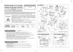
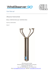
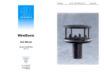
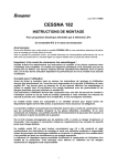
1
WindDisplay
User manual
Doc No. 1086-PS-0050
Issue 06
CE
Gill Instruments Limited
Saltmarsh Park,
67 Gosport Street,
Lymington,
Hampshire.
SO41 9EG
UK
Tel: +44 (0) 1590 613500
Fax: +44 (0) 1590 613501
E-mail: [email protected]
Website: www.gill.co.uk
WindDisplay
February 2005
Document No 1086-PS-0050
Issue 06
FOREWARD ......................................................................................... 2
1. PACKING LIST .................................................................................. 3
2. SUMMARY OF ABBREVIATIONS USED............................................ 3
3. GENERAL ......................................................................................... 4
4. INSTALLATION................................................................................. 6
4.1
Mechanical ............................................................................... 6
4.2
Electrical .................................................................................. 6
4.2.1
Cable layout ....................................................................... 6
4.2.2
Power supply ..................................................................... 7
4.2.3
Connections ....................................................................... 7
4.2.4
Daisy Chain Connections .................................................... 7
5. COMMISSIONING.............................................................................. 8
5.1
Settings via front panel .............................................................. 8
5.1.1
Units and averaging settings ............................................... 9
5.1.2
Lamp test .......................................................................... 9
5.1.3
Deviation setting ................................................................ 9
6. MAINTENANCE............................................................................... 10
7. APPENDIX/DRAWINGS ................................................................... 11
APPENDIX
APPENDIX
APPENDIX
APPENDIX
APPENDIX
1
2
3
4
5
– General assembley .................................................... 12
– Cable information ...................................................... 13
– Electrical connections ................................................ 14
– Daisy chain connections............................................. 15
– Rear view of WindDisplay........................................... 16
Page 1
WindDisplay
February 2005
Document No 1086-PS-0050
Issue 06
FOREWARD
WindDisplay
February 2005
Document No 1086-PS-0050
Issue 06
1. PACKING LIST
This manual refers to the WindDisplay supplied by Gill Instruments.
•
WindDisplay
The WindDisplay is a sophisticated instrument and to achieve optimum
performance, we recommend that you read the whole of this manual before
proceeding to use the equipment.
•
Mounting lugs
•
This manual
Gill products are in continuous development and therefore specifications may be
subject to change without prior notice.
2. SUMMARY OF ABBREVIATIONS USED
ac……………..
Alternating current
Bft
Beaufort scale
dc……………..
Direct current
km/h
Kilometres per hour
kn
Knots
LED………….
Light Emitting Diode
mA
Milliamp
mph
Miles per hour
m/s
Metres per second
PCB……………
Printed Circuit Board
Caution – Copyright Applies:
The information contained in this manual remains the property of Gill Instruments
and as such, it should not be copied or re-produced for commercial gain.
Page 2
Page 3
WindDisplay
February 2005
Document No 1086-PS-0050
Issue 06
WindDisplay
February 2005
3. GENERAL
Document No 1086-PS-0050
Issue 06
Principal characteristics
The Gill digital WindDisplay is a combined wind speed and direction indicator.
The WindDisplay comprises two, 3 digit LED arrays to provide instantaneous wind
speed and maximum or minimum gust data. A double ring of 36 LEDs is used to
indicate instantaneous and average direction information.
Power supply
220Vac
Speed display
3 digit 7 segment LED display 14.3mm height
Gust display
3 digit 7 segment LED display 10.1mm height
The front panel provides three buttons “MENU”, “σ” and ”τ”which may be used to
adjust the brightness of the LEDs, enter a display mode or enter a set up mode.
Direction display
36 LEDs circular colour RED
Direction average
36 LEDs circular colour AMBER
The WindDisplay will accept data output directly from Gill WindObserver and Gill
WindMaster anemometers without the need for additional interfaces. It provides
the power supply to the anemometer and “daisy-chain” connections are available
for additional WindDisplays. See Appendix 1.
Input
RS422
Output
Daisy chain RS422, 300 Baud, ascii 15Vdc supply
to anemometer.
Dimensions
144 x 144 x 94 mm
Weight
Approximately 0.8kg
Scale
Knots, mph, m/s, km/h
Brightness control
From the front panel control
Readout units
m/s, km/h, knots, mph and Bft
The display is housed in a DIN-size casing suitable for flush mounting and must
be mounted in a console or display panel.
The WindDisplay may be user-configured to display the wind speed in various
scales, i.e. miles per hour (mph), metres per second (m/s), knots (kn), kilometres
per hour (km/h) and Beaufort (Bft).
The WindDisplay is available in three versions. The marine version is designed
for use on board ship. The front panel of the marine display has a degree scale
range from 0° to 180° on both sides of the scale.
Standard
Marine
Marine
0° - 359° scale
0° - 180° - 0° scale
0° - 180° - 0° scale NMEA format
Page 4
Page 5
WindDisplay
February 2005
Document No 1086-PS-0050
Issue 06
4. INSTALLATION
WindDisplay
February 2005
4.2.2
INSTALLATION AND COMMISSIONING MUST BE
COMPLETED BY QUALIFIED PERSONNEL
4.1
Power supply
The WindDisplay power supply will be set for 230 Vac.
If the customer requires a different supply voltage, the following
will apply:
Mechanical
Panel mounting of the WindDisplay requires a panel cut-out of 137mm
square. Maximum panel thickness 5mm. Rear access must be provided
for fixing of the tightening clamps and connecting the electric cabling. The
depth of the units is 94mm and an additional clearance of 8mm should be
allowed for the cable connections and strain relief.
4.2
Document No 1086-PS-0050
Issue 06
•
•
4.2.3
The unit can be returned to Gill Instruments for
adjustment.
The Distributor will modify the unit.
Connections
All connections to the WindDisplay are made to the rear of the
display as shown on the drawing in Appendix 3.
Electrical
The WindDisplay utilises a common terminal strip for connections to the
anemometers and ancillary displays. The signal cable between sensor
and display is a 4-core cable with 2 cores for power to the sensor and 2
cores for signal transmission. To reduce interference, the cable must
have a common screen. This screen should be grounded to earth. The
cable may be up to 1 kilometre in length.
Recommended cable: See Appendix 2.
4.2.4
Daisy Chain Connections
The daisy-chain output is used to transmit wind data to a second
WindDisplay. The cable length depends on the type of cable
used but a distance of up to 1000 metres is possible. The cable
should be a twisted pair, screened and the screen should be
grounded at one point only. See Appendix 4.
The WindDisplay provides the 15 Volts dc power supply to the
anemometer.
4.2.1
Cable layout
See Appendix 2.
Page 6
Page 7
WindDisplay
February 2005
Document No 1086-PS-0050
Issue 06
5. COMMISSIONING
WindDisplay
February 2005
5.1.1
Before switching on the mains, check that the power supply is correct as indicated
on the identification label on the rear of the equipment.
Units and averaging settings
When the menu button is pressed the LED in the “average time
window” starts to flash indicating that the selected option is
functioning. It now becomes possible to make a selection using
the arrow up and down buttons. If the menu button is pressed
again, the LED in the units window starts flashing, indicating that
the selected option is on. With the arrow up and down buttons, it
is now possible to select different units for the wind speed.
The anemometer must be configured in the following output formats, depending
on the type of WindDisplay used:Gill Output
NMEA Output
Document No 1086-PS-0050
Issue 06
1Hz (P1), Baud Rate 9600 (B3), Polar Cont (M2)
1Hz (P1), Baud Rate 4800 (B2), NMEA Cont (M5)
If the buttons are not touched for 5 seconds, the display will return
to the normal operating mode.
With no anemometer cable connected, switch on the display and observe the front
panel LEDs. The system will perform an LED test. All LEDs are switched on and
off one by one. When the test is finished the display shows no information on the
LED circle and on both speed displays “---“ is shown.
5.1.2
With both arrow buttons pressed, all the displays and LEDs start
flashing (lamp test). When the interval time for a gust is set to 0
seconds, the gust must be reset manually. This has to be done
by pressing the menu and the arrow down button at the same
time.
Check the voltage at terminal (1) and (2) on the rear panel. This should be 15
Volts dc.
Connect the anemometer as shown in Appendix 3.
When there is no serial information received from the anemometer, the watchdog
circuit in the display unit starts to switch the 15 Volt supply voltage to the sensor
ON and OFF. The supply voltage is on for 10 seconds and if no information is
received from the anemometer, the supply voltage is switched OFF for 5 seconds.
If this occurs during commissioning, check the wiring to the anemometer.
When the display is fully operational and the sensor information is not received for
more than 5 seconds, the display starts to flash indicating that sensor information
is no longer being received by the display unit.
5.1
Settings via front panel
On the front panel of the display there are three push buttons. The
buttons are marked “MENU” “? ”and “? ”. Under normal conditions the
buttons marked “? ” and “? ” are used to adjust the brightness of the
display.
Page 8
Lamp test
5.1.3
Deviation setting
The display provides the possibility to add an offset to the wind
direction. This is very useful for wind systems installed on oil rigs
and for airports if they want to use the magnetic North instead of
true North.
An offset is added in the following way. Press the arrow-up
button “? ” and the menu button. The Gust display starts flashing
and is showing the offset. As long as the display is flashing, the
offset can be changed using the arrow up or arrow down buttons.
The set value is added to the actual wind information from the
anemometer.
Page 9
WindDisplay
February 2005
Document No 1086-PS-0050
Issue 06
WindDisplay
February 2005
Document No 1086-PS-0050
Issue 06
6. MAINTENANCE
7. APPENDIX/DRAWINGS
The Gill WindDisplay unit has no moving parts and requires no routine
maintenance. In the event of failure, the unit must be returned to the authorised
Gill Distributor.
Appendix 1
General assembly
Appendix 2
Cable information
If required, the front panel of the display can be cleaned with a cloth, slightly
moistened with a soft detergent. Ensure that no liquid enters the display unit.
Solvents should not be used and care should be taken to avoid scratching the
front panel.
Appendix 3
Electrical connections
Appendix 4
Daisy chain connections
Appendix 5
Rear view of WindDisplay
Fuses: Glass fuses 5 x 20 mm
50mA for 230 Vac
The fuse can be reached as follows
Switch off the main supply and disconnect all the wiring on the rear of the
display.
Remove the four 2.5mm screws on the rear of the display.
Remove the front window, pull on a corner with both hands.
Hold the front of the unit down and remove the whole case.
The fuse is positioned on the PCB see Appendix 5.
Page 10
Page 11
WindDisplay
February 2005
Document No 1086-PS-0050
Issue 06
APPENDIX 1 – General assembley
WindDisplay
February 2005
Document No 1086-PS-0050
Issue 06
APPENDIX 2 – Cable information
Page 12
Page 13
WindDisplay
February 2005
Document No 1086-PS-0050
Issue 06
APPENDIX 3 – Electrical connections
Page 14
WindDisplay
February 2005
Document No 1086-PS-0050
Issue 06
APPENDIX 4 – Daisy chain connections
Page 15
WindDisplay
February 2005
Document No 1086-PS-0050
Issue 06
APPENDIX 5 – Rear view of WindDisplay
1 = Anemometer Supply V2 = Anemometer Supply V+
7 = RS422 IN (-)
8 = RS422 IN (+)
9 = Daisy Chain OUT (-)
10 = Daisy Chain OUT (+)
11 = Pulse speed input (-)
12 = Pulse speed input (+)
Page 16