1
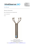
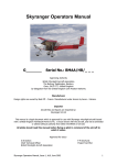
WindMaster &
Windmaster Pro
Ultrasonic Anemometer
User Manual
Doc No. 1561-PS-0001
Issue 02
Gill Instruments Limited
Saltmarsh Park,
67 Gosport Street,
Lymington,
Hampshire.
SO41 9EG
UK
Tel: +44 (0) 1590 613500
Fax: +44 (0) 1590 613501
E-mail: [email protected]
Website: www.gill.co.uk
WindMaster and WindMaster Pro
1561-PS-0001.
Issue 2 August 2006
________________________________________________________________________________________________________________________
Contents
Contents
1
1.
FOREWORD
3
2.
INTRODUCTION
4
3.
PRINCIPLE OF OPERATION
Polar definition
U, V, and W axes definition
Effects of temperature, barometric pressure, rainfall and humidity
Measurement sequence
Signal processing
5
6
6
7
7
7
4.
SPECIFICATION
8
5.
PRE-INSTALLATION
5.1. Equipment supplied
5.2. Software
5.3. Options
5.4. Accessories
5.5. Packaging
5.6. Installation requirements
PC requirement
Other equipment
Connection
Power supply
9
9
9
9
9
9
9
9
10
10
10
6.
INSTALLATION
6.1. Installation Guidelines
6.2. Bench system test
6.3. Cable type
6.4. Cable length
6.5. Connections
Cable assembly
Connector Pin & Conductor positions
Grounding (earthing)
6.6. Connection to a PC using RS 232
6.7. Connection to a PC using RS 422
6.8. Connection to a PC via a Power and Communications Interface
Environmental
Electrical Power Requirements
Connector Pin and Cable Assignments for PCI
6.8. Networking using RS485
6.9. Mechanical installation
Location
Orientation
Alignment
Corrosion
Grounding (Earthing)
Cable strain relief
Flange mounting
Pipe mount adaptor
11
11
11
11
12
13
14
15
17
18
18
19
19
19
19
22
23
23
23
23
23
23
23
24
24
7.
MESSAGE FORMATS
7.1. Gill format– Polar, Continuous (Default format)
WindMaster node address
Horizontal wind direction
Horizontal wind speed
26
26
26
26
26
2
WindMaster and WindMaster Pro
1561-PS-0001.
Issue 2 August 2006
________________________________________________________________________________________________________________________
7.2.
7.3.
Vertical wind speed
Units
Speed of Sound (SOS)
Sonic temperature
Status
Checksum
Output rate (not displayed)
Gill format – UVW, Continuous
Gill format – Polled (Polar or UV)
26
26
27
27
27
27
27
27
27
8.
ANALOGUE INPUTS
8.1. Analogue Inputs
8.2. PRT input
28
28
28
9.
ANALOGUE OUTPUTS
Output allocations
Output types
Voltage outputs
Current outputs
Scaling
Polar wind direction wraparound
28
28
29
29
29
29
29
10. CONFIGURING
10.1. WIND software
10.2. Configuring using Hyperterminal
Setting up
Entering Configuration mode
Returning to Measurement mode
Checking the configuration
Changing settings
Command List
30
30
34
34
34
34
35
35
36
11. MAINTENANCE & FAULT-FINDING
11.1. Cleaning
11.2. Servicing
11.3. Fault-finding
11.4. Returning unit
11.5. Status (error) codes
41
41
41
42
42
42
12. TESTS
12.1. Bench test
12.2. Calibration
Standard calibration
Certified calibration
42
43
43
43
43
13. APPENDICES
13.1. Guarantee
43
43
13.2 Electrical Conformity
EC DECLARATION OF CONFORMITY ACCORDING
44
44
1. FOREWORD
Thank you for purchasing a WindMaster or WindMasterPro manufactured by Gill Instruments Ltd. The units have no
customer serviceable parts and require no calibration or maintenance. To achieve optimum performance we recommend
that you read the whole of this manual before proceeding with use.
3
WindMaster and WindMaster Pro
1561-PS-0001.
Issue 2 August 2006
________________________________________________________________________________________________________________________
Gill products are in continuous development and therefore specifications may be subject to change and design
improvements without prior notice.
The information contained in this manual remains the property of Gill Instruments and should not be copied or
reproduced for commercial gain.
2. INTRODUCTION
This manual describes the operation of both the WindMaster (1590-PK-020 + options) and WindMaster Pro (1561-PK020 + options). The instruments replace the previous WindMaster model (1086-PK-046) and WindMasterPro (1352PK-001). Refer to appropriate manuals for these instruments.
The term 'WindMaster' is used in this manual as a general term for both the WindMaster and the WindMaster Pro; they
are robust three axis anemometers, with no moving parts.
The units of wind speed, output rate, and formats are all user selectable.
The WindMaster, constructed in aluminium and carbon fibre, can perform measurements in wind speeds up to 45 m/s.
The WindMaster Pro, constructed from marine grade stainless steel 316, can perform measurements in wind speeds up
to 65 m/s.
Options include up to four analogue input and four analogue output channels (12 or 14 bit resolution for WindMaster;
14 bit resolution for WindMaster Pro. A PRT input is also available (WindMaster Pro only).
Units may additionally be calibrated in a wind tunnel to ISO 16622, traceable to national standards.
WIND software is available free from the Gill website www.gill.co.uk . It is strongly recommended as it provides an
easy, user-friendly interface.
4
WindMaster and WindMaster Pro
1561-PS-0001.
Issue 2 August 2006
________________________________________________________________________________________________________________________
3. PRINCIPLE OF OPERATION
Figure 1 Time of Flight details
The WindMaster measures the times taken for an ultrasonic pulse of sound to travel from an upper transducer to the
opposite lower transducer, and compares it with the time for a pulse to travel from lower to upper transducer.
Likewise times are compared between each of the other upper and lower transducers.
As Figure 1 shows, the air velocity along the axis between each pair of transducers can then be calculated from the
times of flight on each axis.
This calculation is independent of factors such as temperature.
From the three axis velocities, the wind speed is calculated, as either signed U, V, and W , or as Polar and W.
It can be seen from Figure 1 that the speed of sound in air can be calculated from the times of flight. From this the sonic
temperature can be derived from the formula TS1 = C12 / 403
Where
TS1 = Sonic temperature
C1 = Speed of sound
Note the formula does not account for the effect of Humidity
Figure 2 shows the direction and polarity of the U, V and W axes.
5
WindMaster and WindMaster Pro
1561-PS-0001.
Issue 2 August 2006
________________________________________________________________________________________________________________________
Polar definition
The wind speed in the UV plane, with direction in degrees from 0 to 359 °, with respect to the Reference spar (which is
normally aligned to North).
U, V, and W axes definition
+U is defined as towards the direction in line with the north spar as indicated in the diagram.
+V is defined as towards the direction of 90° anti-clockwise from N / the Reference spar.
+W is defined as vertically up the mounting shaft.
6
WindMaster and WindMaster Pro
1561-PS-0001.
Issue 2 August 2006
________________________________________________________________________________________________________________________
Effects of temperature, barometric pressure, rainfall and humidity
The calculated u,v and w components are independent of temperature ,pressure,rainfall & humidity within the operating
parameters of the WindMaster.
The calculated sonic temperature/speed of sound should be corrected by the user for humidity to provide and indication
of ambient temperature.
Measurement sequence
The table shows the firing sequence of the transducers.
Measurement Sequence
The sample rate is automatically selected to either 32 or 40 Hz, depending on the output rate configured
Measurement Period
Ultrasonic Measurement Axis
Transducer Firing
Analogue Input Measurement
Serial Communications
1
L > U
10 ms max
2
3
U > L
L > U
U > L
L > U
1, 2, 3 or 4, PRT (one in four)
U > L
Next cycle
1
L > U
U > L
2
L > etc
Data from previous meas.
L > U Indicates lower to upper transducer firing
U > L Indicates upper to lower transducer firing
Analogue inputs 1 & 2 are sampled every measurement period
Analogue inputs 3 & 4 are sampled alternatively ( ie half of measurement rate
PRT is sampled once every 4 firings (ie quarter of measurement rate)
Signal processing
Instantaneous Sampling
The WindMaster can be configured to output the sampled data direct at the selected output rate without any averaging "Instantaneous Sampling". Alternatively data can be sampled at 32 or 40 Hz and averaged (see section 10.2 PX). This
applies for wind data and speed of sound. All samples are transmitted with a status code.
Retries Enabled
If this mode is selected, if a problem sample is detected, the unit will attempt another ultrasonic firing within the set
time parameters.
Calibration Enabled /Disabled
The on-board calibration (providing compensation for spar and transducer shadowing), can be disabled, returning the
unit to raw, uncorrected operation.
7
WindMaster and WindMaster Pro
1561-PS-0001.
Issue 2 August 2006
________________________________________________________________________________________________________________________
4. SPECIFICATION
WindMaster
Outputs
Output rate
WindMaster Pro
Sample rate (automatically selected)
1, 2, 4, 8, 10, 16, 20, (32 option) Hz
32 or 40 Hz
1, 2, 4, 8, 10, 16, 20, 32 Hz
32 or 40 Hz
Units of measure
Format
Averaging
m/s, mph, KPH, knots, ft/min
UVW or Polar
Flexible 0 - 3600 s
m/s, mph, KPH, knots, ft/min
UVW or Polar
Flexible 0 - 3600 s
0 - 45 m/s
0.01 or 0.001 m/s
< 1.5% RMS
< 1.0 % RMS
0 - 65 m/s
0.01 or 0.001 m/s
< 1.5% RMS
< 1.0 % RMS
0 – 359.9°
10 or 0.10
0 – 359.9°
10 or 0.10
2°
2°
0.5°
0.5°
300 -370 m/s
0.01 m/s
300 -370 m/s
0.01 m/s
< ± 0.5% @ 20°C
9 -30 Vdc, ( 55 mA @ 12 Vdc)
(excluding analogue outputs)
< ± 0.5% @ 20 °C
9 -30 Vdc, ( 55 mA @ 12 Vdc)
(excluding analogue outputs)
RS232, RS422, RS485
network up to 8 anemometers
2400 - 57600
RS232, RS422, RS485
network up to 8 anemometers
2400 - 57600
Resolution 12 or 14 bit
User selectable full scale wind speed
Resolution 14 bit
User selectable full scale wind speed
0-20 mA, 4-20 mA, 0-5 V,
Wind Speed
Range
Resolution
Accuracy (12 m/s) (Standard)*
Accuracy (12 m/s) (to special order)* #
Direction
Range
Resolution
Accuracy (12 m/s) (Standard)*
Accuracy (12 m/s) (to special order)* #
Speed of Sound
Range
Resolution
Accuracy
Power requirement
Digital output
Protocol
(ASCII)
Baud rates
Analogue outputs (optional)
4 channels
Selectable range
Output type
Analogue inputs (optional)
Up to 4 single-ended
or 2 differential
Input range
Sonic temperature
Range
General
Weight
Size
Environmental
Operating temperature
Humidity
Precipitation
EMC
0-20 mA, 4-20 mA, 0-5 V, ±5 V,
0-2.5V
±5V,0.2.5V
Resolution 12 or 14 bit
Resolution 14 bit,
plus PRT 100ohm (option)
±5 V
±5 V
-40 °C to +70 °C
-40 °C to +70 °C
1.0 kg
750 mm x 240 mm
IP65
1.7 kg
750 mm x 240 mm
IP65
-40 °C to +70 °C
< 5 % to 100 %
Operation up to 300 mm / hour
Emissions BS EN 61000 - 6 - 3
Immunity BS EN 61000 - 6 - 2
-40 °C to +70 °C
< 5 % to 100 %
Operation up to 300 mm / hour
Emissions BS EN 61000 - 6 - 3
Immunity BS EN 61000 - 6 - 2
* Accuracy specification applies for wind speed up to range maximum, and for wind incidence up to ± 30 ° from the horizontal.
# Custom calibration (to be specified when ordering, or unit can be returned for calibration)
- Wind tunnel calibration is in accordance with ISO 16622 and traceable to national standards.
8
WindMaster and WindMaster Pro
1561-PS-0001.
Issue 2 August 2006
________________________________________________________________________________________________________________________
5. PRE-INSTALLATION
5.1.
Equipment supplied
WindMaster or WindMaster Pro
Connector assembly comprising
Installation kit
User Manual (this document)
5.2.
31 way Clipper connector
Solder bucket pins
Sealing gland and washer
Four M6 stainless steel nuts, bolts and shake-proof washers
Software
WIND software is available free at www.gill.co.uk , and is strongly recommended as it provides an easy, user-friendly
interface.
5.3.
Options
Notes
These options must be specified when ordering the WindMaster or WindMaster Pro.
See Section 4 Specification for more detail
WindMaster
WindMaster Pro
Four Analogue outputs
12 or 14 bit (specify)
14 bit
Four Analogue inputs
12 or 14 bit (specify)
14 bit
PRT input
Not available
Specify when ordering
Wind tunnel calibration,
traceable to national standards
Specify when ordering *
Specify when ordering *
* Units may be returned to Gill for Wind tunnel calibration.
5.4.
Accessories
Item
Travelling case - Portable protective case
Spare 31 way Clipper connector
Spare 15m lead - one end free, other end fitted with Clipper pins
Power Supply and Interface Unit (PCI)
Pipe mount adaptor
5.5.
Part No
1210 - 30 -074
1561 - PK - 050
1561 - 10 - 018
1189 - PK - 021
1561 - 30 - 025
Packaging
Whilst the WindMaster is being moved to its installation site, the unit should be kept in its packaging. All the packaging
should be retained for use if the unit has to be returned at any time.
Note that if the WindMaster is to be regularly moved around, a travelling case is available as an optional extra
5.6.
Installation requirements
PC requirement
The new WIND software will operate with any PC with Windows software from Windows 98 onwards.
The PC must be fitted with a suitable interface to match the chosen communication format - RS232, RS422, or
RS485. Alternatively a Gill Power Supply and Interface (PCI) may be used to convert RS422/485 output to RS232
9
WindMaster and WindMaster Pro
1561-PS-0001.
Issue 2 August 2006
________________________________________________________________________________________________________________________
Other equipment
Analogue inputs / outputs must be compatible with the options fitted to the WindMaster or WindMaster Pro.
See Sections 8 and 9
Connection
o
o
o
o
o
The unit is fitted with a modified 31 way Clipper industrial plastic connector (shell size 3), and supplied with a
mating plug with solder bucket pins for installation by the user.
The cable should be securely fixed with cable clamps or equivalent, so that the cable is not under stress at the
plug.
There are restrictions on the maximum cable lengths for correct operation. See 6.4
The cable should be routed up the inside of the mounting tube.
See 6.3 for cable specification.
Power supply
o
o
The WindMaster requires a DC supply of between 9 – 30 V DC.
Typical current drain
55 mA @ 12 V (excluding analogue outputs)
10
WindMaster and WindMaster Pro
1561-PS-0001.
Issue 2 August 2006
________________________________________________________________________________________________________________________
6. INSTALLATION
6.1.
Installation Guidelines
As with any sophisticated electronics, good engineering practice should be followed to ensure correct operation.
Always check the installation to ensure the WindMaster is not affected by other equipment operating locally,
which may not conform to current standards, e.g. radio/radar transmitters, boat engines, generators etc.
Guidelines –
o Avoid mounting in the plane of any radar scanner – a vertical separation of at least 2m should be achieved.
o Radio transmitting antennas, the following minimum separations (all round) are suggested
•
VHF IMM – 1m
•
MF/HF – 5m
•
Satcom – 5m (avoid likely lines of sight)
Use cables recommended by Gill. If cables are cut and re-connected incorrectly (perhaps in a junction box) then
EMC performance may be compromised if cable screen integrity is not maintained.
Earth loops should not be created – wire the system in accordance with the installation guidelines.
Ensure the power supply operates to the WindMaster specification at all times.
6.2.
Bench system test
Note : Prior to physically mounting the WindMaster in its final location, we strongly recommend that a
bench system test is carried out to confirm the system is configured correctly, is fully functional and
electrically compatible with the selected host system and cabling (preferably utilising the final cable
length). The required data format, units, output rate, and other options should also all be configured at
this stage.
6.3.
Cable type
An RS232 / RS422 compatible cable (as appropriate) should be used, with the number of twisted pairs matching the
application.
Generic description – Twisted pairs with drain wire, screened with aluminised tape, with an overall PVC sheath.
Wire size 7/0.2mm (24 AWG)
Gill 15m lead - A nine pair, 15metre lead, with one end free and the other end fitted with Clipper pins, is available as
an accessory from Gill, see 5.4 Accessories for part number.
The table shows some suitable manufacturers’ references; other manufacturers’ equivalents can be used.
No. of pairs
9
Gill ref.
026 - 02663
Belden ref.
8774
Batt electronics ref.
91009
The cable allows for the connection of all:Power inputs
Digital inputs
Analogue inputs
Analogue Outputs
Note: If PRT input option is selected customer must compromise on the number of enclosed inputs or outputs. If PRT is
connected you must sacrifice two analogue inputs or outputs.
11
WindMaster and WindMaster Pro
1561-PS-0001.
Issue 2 August 2006
________________________________________________________________________________________________________________________
6.4.
Cable length
The maximum cable length is dependent on the chosen communication format (RS232, RS422 or RS485), the baud
rate, and, to a lesser extent, on the cable type and the local electrical ‘noise’ level.
Communication format
Baud rate
Max. cable length
RS232
9600
6.5 m (20 ft) or if using Cat 5 cable see
manufacturers recommendations
RS422/485
9600
1 km (3200 ft)
Analogue outputs voltage
N/A
6.5 m (20 ft)
Analogue outputs - current
N/A
Resistance dependent (max 250 Ω)
The table shows the typical maximum lengths at the given baud rates, using the recommended cable. If any problems of
data corruption etc are experienced, then a slower baud rate should be used. Alternatively, a thicker or higher
specification cable can be tried.
12
WindMaster and WindMaster Pro
1561-PS-0001.
Issue 2 August 2006
________________________________________________________________________________________________________________________
6.5.
Connections
Important
Do NOT join any of the cores of the cable together.
Any cores not used should be isolated.
Do NOT connect the unit’s analogue output 0V or power 0V to the screen or ground / earth.
The integrity of the screen of each pair should be maintained throughout the cable run.
Avoid long grounding loops.
For maximum lightning protection it is essential that the unit is properly grounded via its mounting base.
Function
Remarks
Pin No
TXA( -)
Anemometer Transmit -
1
TXB (+)
Anemometer Transmit +
2
RXB (+)
Anemometer Receive +
5
RXA (-)
Anemometer Receive -
6
Communications mode
Polarity sets comms mode:
Connect to V+ for RS232
Connect to 0V for RS422/485
If left unconnected unit will
default to RS422/485
4
Power V+
9 – 30 V
11
Power 0V
Use also for digital comms 0V
12
Analogue Output 1
8
Analogue Output 2
14
Analogue Output 3
9
Analogue Output 4
15
PRT Excitation +
19
PRT Excitation -
20
PRT Sense +
25
PRT Sense -
26
Analogue Input 1
27
Analogue Input 2
28
Analogue Input 3
29
Analogue Input 4
24
Analogue Grounds
Use the most convenient pin
10, 16, 17
Screens
Use the most convenient pin
3, 7, 21, 30, 31
Not connected
13, 18, 22, 23
13
WindMaster and WindMaster Pro
1561-PS-0001.
Issue 2 August 2006
________________________________________________________________________________________________________________________
Cable assembly
Open the pack of parts (1561-PK-050) provided with the WindMaster.
Strip the cable and solder the contact pins to the cores (please note that the connector supplies the correct strain relief
for cables with an outside diameter of 6-12mm).
Put the parts on the cable in the order as shown below.
Whilst squeezing the red retainers in the direction of ARROW A, pull in the direction of ARROW B.
A
B
Your connector should now resemble the connector in the picture above.
14
WindMaster and WindMaster Pro
1561-PS-0001.
Issue 2 August 2006
________________________________________________________________________________________________________________________
Insert each contact pin until you feel a slight click. If you have inserted the contact into the incorrect hole it can
be removed at this point by simply pulling it out. Please note there will be some resistance.
Continue to insert all of the contacts you require in accordance with the diagram below.
Connector Pin & Conductor positions
The drawing above shows the pin positions & the colour of the wire conductors, together with
position of conductor screens. This information must be used on conjunction with the information
shown in 6.5 connections. If the PRT option is selected you may have to sacrifice two analogue
inputs or outputs.
15
WindMaster and WindMaster Pro
1561-PS-0001.
Issue 2 August 2006
________________________________________________________________________________________________________________________
Once all of the contacts are inserted push the red retainer into place.
NB. The retainer can only be pushed back into place if the contacts are fully engaged.
Fit the connector to the WindMaster so that you can now finish assembling the connector.
Screw the back-shell onto the connector until it is fully in place. Please note that the final rotations can be slightly
stiff
Screw the cable clamp into the back shell
16
WindMaster and WindMaster Pro
1561-PS-0001.
Issue 2 August 2006
________________________________________________________________________________________________________________________
Now screw the cable-clamping nut into place
.
The connector can now be removed from the WindMaster.
Grounding (earthing)
To ensure correct operation, and for maximum protection against lightning, the anemometer MUST be correctly
grounded (earthed) via its mountings. Inadequate grounding will degrade anemometer performance, particularly in the
presence of radio frequency interference.
The unit MUST be connected to an appropriate grounding point with a minimum of 6mm² copper wire, via the M6 base
screws. The primary earth for the anemometer must be provided via the base screws and not via the cable screens.
17
WindMaster and WindMaster Pro
1561-PS-0001.
Issue 2 August 2006
________________________________________________________________________________________________________________________
6.6.
Connection to a PC using RS 232
Notes
1.
2.
3.
Using RS232, the cable length for reliable operation is limited to 6.5m (20ft) @ 9600 Baud. See 6.4
For longer cable runs, we recommend using the WindMaster configured with RS422 output, and a RS422/232
converter at the PC. See 6.7
Ensure WindMaster is configured for RS232. See Section 10 Configuring
WindMaster
connector
Pin nos.
Signal names
6.7.
TXA (-)
RXA (-)
1
6
Comms Mode link to Power V+ (Pin 11)
4
Screen
(Use the most convenient pin)
3, 7, 21,
30 or 31
Power V+
Power 0V
11
12
Cable
2 twisted pairs
Screen and
drain wires
PC
Typical Serial connector
(9 Way ‘D’ )
Signal
Pin nos.
names
RXD
2
TXD
3
Signal
comms
5
Ground
Chassis
ground
N/A
DC Power
supply
9 – 30V
+
–
Connection to a PC using RS 422
Notes
1.
2.
The PC must be fitted with an internal or external RS422 / RS232 converter.
Configure WindMaster for RS 422 by linking Comms Mode line (Pin 4) to 0V (Pin 12)
PC with RS422/232
converter
WindMaster connector
Signal names
TXB(+)
TXA(–)
RXB(+)
RXA(-)
Pin nos.
Cable –twisted
pairs
Signal names
RXB(+)
RXA(–)
TXB(+)
TXD –
2
1
5
6
Signal Ground
Screen
(Use the most convenient pin)
Comms Mode
- link to Power 0V (Pin 12)
or leave unconnected
Power V+
Power 0V
3, 7, 21,
30 or 31
Screen and drain
wires
Chassis ground
4
+
–
11
12
18
DC Power
supply
9 – 30V
WindMaster and WindMaster Pro
1561-PS-0001.
Issue 2 August 2006
________________________________________________________________________________________________________________________
6.8.
Connection to a PC via a Power and Communications Interface
Dependent upon system requirements the WindMaster unit can be operated with the Power and Communications and
Interface unit (PCI), which can be ordered as an optional extra. Connect WindMaster via RS422 port; then connect
computer to RS232 port on PCI.
Environmental
The Desktop PCI is intended for use in a protected environment and provides interfacing to a single anemometer.
RS232, and RS422 ports are provided. The PCI is not intended for outdoor use.
PCI Electrical Power Requirements
1)
2)
3)
100Vac - 120Vac, 10VA for the 115V switch position
200Vac - 250Vac, 10VA for the 230V switch position
9 - 30Vdc, 55mA excluding analogue outputs (anemometer)
8 - 15Vdc, 50mA max (interface)
3 fuses protect the unit:
1.
Externally accessible
2.
Internally accessible
315 mA(T) for 115/230v operation
500 mA (T) AUX
500 m A(T) ANEM
Connector Pin and Cable Assignments for PCI
Anemometer connector - 15 way
Pin
Designation
1
Screen
2
RS422_RXB (+)
3
RS422_TXB (+)
4
Digital 0V, Signal ground
5
Supply V+
6
Analogue output V1
7
Not used
8
Analogue output V2
9
RS422_RXA (-)
10
RS422_TXA (-)
11
Supply V12
Analogue output V4
13
Analogue 0V
14
Not used
15
Analogue output V3
19
WindMaster and WindMaster Pro
1561-PS-0001.
Issue 2 August 2006
________________________________________________________________________________________________________________________
DC Supply - 4 way
Pin
Designation
1
Interface V+
2
Interface V3
Anemometer V4
Anemometer V+
RS232 Output - 9 way
Pin
Designation
1
DCD
2
RX data
3
TX data
4
DTR
5
Signal Ground
6
DSR
7
RTS
8
DCD
9
RI
RS422 Input/Output - 9 way
Pin
Designation
1
Not connected
2
Not connected
3
Not connected
4
RS422_RXA (-)
5
Signal ground
6
RS422_TXA (-)
7
RS422_TXB (+)
8
RS422_RXB (+)
9
Earth
20
WindMaster and WindMaster Pro
1561-PS-0001.
Issue 2 August 2006
________________________________________________________________________________________________________________________
21
WindMaster and WindMaster Pro
1561-PS-0001.
Issue 2 August 2006
________________________________________________________________________________________________________________________
6.8.
Networking using RS485
Notes
1.
2.
3.
4.
5.
Up to 8 WindMasters can be networked as Slaves.
WindMasters must be configured for RS485 by linking Comms Mode line (Pin 4) to 0V (Pin 12).
WindMasters must be in Polled mode, with each device given a unique node address before they are
connected to the network buss.
The Master unit can be any suitable control device fitted with a RS485 interface card, such as a PC or Data
logger.
Power needs to be supplied to each unit in the network.
Master eg PC with RS485 card
Signal names
WindMaster connector
Signal names
TXB(+)
RXB(+)
TXA(-)
RXA(-)
Pin nos.
2
5
1
6
T/RXB(+)
T/RXA(-)
Signal ground
Comms Mode - link
to Power 0V (Pin 12)
4
Screen (Use the most
convenient pin)
3, 7, 21,
30 or 31
Power V+
Power 0V
11
12
Screen and drain wires
Chassis ground
+
–
DC Power supply
9 – 30V
To next unit
(Up to 8 units)
22
WindMaster and WindMaster Pro
1561-PS-0001.
Issue 2 August 2006
________________________________________________________________________________________________________________________
6.9.
Mechanical installation
Before installing, it is strongly recommended that a bench test is carried out.
Location
Select a position so that the unit is clear of any structure which may obstruct the airflow or induce turbulence.
Do NOT mount the WindMaster in close proximity of high-powered radar or radio transmitters. A site survey may be
required if there is any doubt about the strength of external electrical noise.
Orientation
Normally the WindMaster is mounted vertically, ensuring a horizontal Measuring Plane.
However, the unit may be mounted with the Measurement Plane set to any required orientation, provided the sealing
gasket is fitted to the flange.
Alignment
The reference north spar as indicated by a notch (that is in the direction line with north) which is also indicated on the
base of the unit by another notch.
Corrosion
Careful note should be taken of the possibility of galvanic corrosion by incorrect mounting. It is vital that only stainless
steel fixings are used and that the instrument is insulated from the mounting surface with the rubber gasket. This will
ensure that the anemometer will provide long service under extreme conditions such as marine.
Grounding (Earthing)
For protection against lightning the WindMaster MUST be earthed via its mountings.
Cable strain relief
Fit strain relief when installing such that the weight of the cable is supported and does not put a strain on the connector.
23
WindMaster and WindMaster Pro
1561-PS-0001.
Issue 2 August 2006
________________________________________________________________________________________________________________________
Flange mounting
Mount the unit to a suitable surface, using the flange gasket and the M6 nuts, bolts and washers provided, ensuring that
the clearance for the connector is maintained as shown on Figure 3.
Pipe mount adaptor
The pipe mount adaptor enables the WindMaster to be fitted directly to a standard 1.5 inch BSP pipe (Pipe size OD
1.9", ID 1.5", wall thickness 0.2). The pipe mount adaptor must be ordered from Gill.
The WindMaster connector must be connected to the WindMaster before the pipe mount adaptor is attached to the
WindMaster. Pass the cable (fitted with the 31 way Clipper plug) through the tube. Connect the plug by twisting it
whilst pushing it gently into the socket on the WindMaster. When it locates, twist the outer sleeve clockwise to connect
and lock the plug.
Fix the pipe mount adaptor to the pipe using the 2 stainless steel screws provided.
Note: the customer MUST fit appropriate strain relief to the cable - this is particularly important with pipe mounting.
Mount the WindMaster unit to the pipe mount adaptor using the flange gasket and the M6 nuts, bolts and washers
provided.
24
WindMaster and WindMaster Pro
1561-PS-0001.
Issue 2 August 2006
________________________________________________________________________________________________________________________
Fig 4
Pipe Mount Adaptor
25
WindMaster and WindMaster Pro
1561-PS-0001.
Issue 2 August 2006
________________________________________________________________________________________________________________________
7. MESSAGE FORMATS
On applying power to the WindMaster, it will automatically operate in the Measurement Mode and provide wind
measurements in one of the following formats:
Gill – Polar, Continuous (default format)
Gill - UVW, Continuous
Gill – UVW Polled
Gill – Polar Polled
Note : In this Section, the default settings are shown in Bold.
Information on how to change the formats and all the settings follows in Section 10 CONFIGURING.
7.1.
Gill format– Polar, Continuous (Default format)
<STX>Q, 229, 002.74, +000.46, 341.29, 21.01, M, 00, <ETX> 06
WindMaster
node address
Horizontal
wind direction
Horizontal
wind speed
Vertical
wind speed
Speed of sound
and/or temperature
(if enabled)
Units
Status
WindMaster node address
The default setting is ‘Q’. If there is more than one WindMaster in a network, the others MUST be renamed (R to Z), so
that each WindMaster is uniquely identified.
Horizontal wind direction
Indicated in degrees, from 0 to 359°, with respect to the WindMaster North marker.
In fixed field mode and when the wind speed is below 0.05 metres/sec, the direction will not be calculated, but the last
calculated direction above 0.05 m/s will be output. (The threshold of 0.05 m/s is the default setting; it is userconfigurable)
Horizontal wind speed
Shows the wind speed in the U / V Plane. See Fig 2
Vertical wind speed
Shows the magnitude of wind speed in the W axis. See Fig 2
Units
The Units identifier shows the units in which the wind speeds are measured.
Units
Metres per second (default)
Knots
Miles per hour
Kilometres per hour
Feet per minute
Identifier
M
N
P
K
F
26
WindMaster and WindMaster Pro
1561-PS-0001.
Issue 2 August 2006
________________________________________________________________________________________________________________________
Speed of Sound (SOS)
If enabled, this is displayed in metres per second.
Sonic temperature
If enabled, this is displayed in degrees C.
Status
This indicates either correct operation - Code 00 - or status code. See 11.5 for explanation of codes.
Checksum
This enables the host system to check that the data has been correctly received. This is the EXCLUSIVE – OR of the
bytes between (and not including) the <STX> and <ETX> characters.
<STX>
Start of string character (ASCII value 2)
<ETX>
End of string character (ASCII value 3)
Output rate (not displayed)
The WindMaster delivers wind information at rates from 1 (default setting) to 32 outputs / second.
[The sample rate (40 or 32 Hz) is chosen automatically to be an appropriate multiple of the output rate.]
Data can be instantaneous or averaged (see section 10)
7.2.
Gill format – UVW, Continuous
In this mode, the wind speed outputs are given as signed (ie. positive or negative) speeds along the
U axis, V axis and the W (vertical) axis.
The definition of the U, V, and W axis are shown in Figure 2.
<STX>Q, +001.59, - 002.74, +000.27, 341.29, 21.01, M, 00, <ETX> 2D
WindMaster
node address
U axis
speed and
polarity
V axis
speed and
polarity
W axis
speed and
polarity
Speed of sound
and/or temperature
(if enabled)
Units
Status
All the other parameters are as described in Section 7.1.
7.3.
Gill format – Polled (Polar or UV)
When in the Polled mode, an output is only generated when the host system sends a Poll signal to the WindMaster
consisting of the WindMaster Unit Identifier – that is, the relevant letter Q – Z.
The output formats are otherwise as described in Sections 7.1 and 7.2.
The commands available in this mode are :
Description
WindMaster Unit Identifier
Enable Polled mode
Disable Polled mode
Request WindMaster Unit
Identifier
Enter Configuration mode
Command
Q ….. Z
?
!
&
WindMaster response
Wind speed output generated
(none)
(none)
Q ….. Z (as configured)
*<N>
CONFIGURATION MODE
Where <N> is the Unit Identifier.
27
WindMaster and WindMaster Pro
1561-PS-0001.
Issue 2 August 2006
________________________________________________________________________________________________________________________
8. ANALOGUE INPUTS
Options of four analogue inputs and outputs must be specified when ordering.
8.1.
Analogue Inputs
The input range is fixed at ± 5V
For pin connections see 6.5 Connections. (Must be specified when ordering)
Note
The Analogue inputs must be enabled if they are to be used - See Section 10 Configuring
Specification
8.2.
Input range
- 5 V to + 5 V
Common mode input range
±5V
Input impedance
310 K ohm in series with 2.5 V
Resolution
12, 14 bit (as installed)
PRT input
Available on the WindMaster Pro only. (Must be specified when ordering ).
The PRT input is designed to work with any 4 wire PRT that meets IEC60751.
Pin Nos
19
25
PRT excitation +
PRT sense +
PRT 100
26
20
PRT sense PRT excitation –
9. ANALOGUE OUTPUTS
Options of four analogue inputs and outputs must be specified when ordering.
Information on how to change the formats and all the settings follows in Section 10 CONFIGURING.
Output allocations
Each of the outputs can be configured to one of the following;Polar direction, Polar magnitude, U, V, W, Speed of Sound, Status
28
WindMaster and WindMaster Pro
1561-PS-0001.
Issue 2 August 2006
________________________________________________________________________________________________________________________
Output types
They are user-configurable as Voltage 0V to 5V or -2.5V to +2.5V or –5V to +5V, or Current 4 -20 mA or 0 20mA.
Voltage outputs
The output impedance is less than 1 ohm. To prevent inaccuracies, the outputs should be connected to an input with an
impedance greater than 10KΩ.
Current outputs
Important
When using the current outputs, the load resistance between the Output and Ground
must be <= 250 ohms, including cable resistance.
This is to ensure that the voltage levels on the Analogue outputs does not exceed 5V.
Scaling
This is user-configurable to 5, 10, 20, 30, 40, 50, 60, or 120 m/s full scale.
Using 50m/s as an example, this defines the outputs as follows
Output
U, V, W or Polar
-50 m/s
+50 m/s
Voltage
0 to 5V
Voltage
± 2.5V
Voltage
± 5V
-2.5
+2.5
0
+5
Current
4 - 20 mA
-5
+5
4
20
Current
4 - 20 mA
0
20
Polar wind direction wraparound
The wind direction in Polar mode can be configured for either 360° or 540° Wraparound. If the 360° mode is used with
a chart recorder, large swings of the recorder pen will be experienced each time the wind direction passes between 0 and
359°. Using the 540° mode, when the wind first changes from 0° to 359°, there will be a step change on the output, but
after this first time the output will change smoothly each time the wind passes through 360°. (Similarly, the first time
the wind veers from 539° to 180°, there will be a step change, after which the output will change smoothly).
Output
Voltage
0 to 5V
Voltage
± 2.5V
Current
4 - 20 mA
Current
0 - 20 mA
360° wraparound
0°
0.00
- 2.50
4.00
0.00
180°
2.50
0.00
12.00
10.00
360°
5.00
+2.50
20.00
20.00
0°
0.00
-2.50
4.00
0.00
180°
1.67
-0.83
9.33
6.67
360°
3.33
+0.83
14.67
13.33
540°
5.00
+2.50
20.00
20.00
540° wraparound
29
WindMaster and WindMaster Pro
1561-PS-0001.
Issue 2 August 2006
________________________________________________________________________________________________________________________
10.
CONFIGURING
It is strongly recommended that WIND software (available free from the Gill website www.gill.co.uk ) is used to
configure the WindMaster.
A less preferred option for configuring is using a terminal emulation package, using command codes
These are both described in the sections below.
Note Certain combinations of output rate, baud rate and message type may be unsupported.
10.1. WIND software
Download the WIND software from the Gill website www.gill.co.uk .
Assuming the WindMaster has been correctly connected to the PC and a Power Supply, the opening menu will show the
WindMaster in Measurement mode. A short Start message will be displayed, followed by continuous wind information
displayed - the default setting being Polar, with the unit of measure Metres per second (m/s).
If a message similar to the one below is displayed, click Tools and Synch Comms in the tool bar and the system will be
synchronised and correct data displayed.
If after Synch Comms there is still a problem with start up, switch power to anemometer off and then on again and
repeat procedure.
30
WindMaster and WindMaster Pro
1561-PS-0001.
Issue 2 August 2006
________________________________________________________________________________________________________________________
The unit is set to factory default 1 Hz output and in Polar mode. A typical message format is shown below:
If you need to review your instrument settings click Tools and Report config in the tool bar.
When selected a similar message to that below will be displayed.
31
WindMaster and WindMaster Pro
1561-PS-0001.
Issue 2 August 2006
________________________________________________________________________________________________________________________
To change the WindMaster configuration click Tools and Wizard in the tool bar
A typical screen is shown below. Customer is able to adjust all the settings as required taking into account the options
selected at time of order
32
WindMaster and WindMaster Pro
1561-PS-0001.
Issue 2 August 2006
________________________________________________________________________________________________________________________
When the changes are complete the Wizard will display a confirmation of the changes with all changes shown in red,
this may be printed as a hard copy if required. Click next and the WindMaster will be re-configured and will return to
measurement mode.
33
WindMaster and WindMaster Pro
1561-PS-0001.
Issue 2 August 2006
________________________________________________________________________________________________________________________
10.2. Configuring using Hyperterminal
Note – Other terminal emulators can be used to configure the WindMaster in a very similar way.
Setting up
1.
2.
3.
4.
5.
6.
Decide on an available Com port that you want to use (Usually Com1).
Run Hypertrm.exe (Typically accessed via Start Programs Accessories Communications Hyperterminal)
Create a New Connection (File New Connection)
Enter a Name (eg WindMaster) .
Change ‘Connect Using’ to ‘Direct to Com 1’ (or other Com port as required)
Adjust the Port settings to match WindMaster settings. WindMaster default settings are :
Bits per second 19200
Data bits 8
Parity None
Stop bits 1
Flow Control (Handshaking) None
Assuming the WindMaster has been correctly connected to the PC and a Power Supply, the opening menu will show the
WindMaster in Measurement mode. A short Start message (Figure 9) will be displayed, followed by continuous wind
information displayed - the default setting being Polar, with the unit of measure Metres per second (m/s).
Figure 9
Typical Start message
Entering Configuration mode
From Continuous mode
*
From Polled mode
*N
where N is the Unit identifier (a letter between Q and Z)
The WindMaster responds with a CONFIGURATION MODE message, stops reporting wind measurements, and waits
for a command (as detailed below).
Returning to Measurement mode
Q ENTER
The WindMaster responds with wind measurements immediately when in Continuous mode,
or on receipt of a Poll signal when in Polled mode.
34
WindMaster and WindMaster Pro
1561-PS-0001.
Issue 2 August 2006
________________________________________________________________________________________________________________________
Checking the configuration
We recommend that, as a standard procedure, you use this command prior to, and after, changing any settings. It shows
the current settings for most of the alterable settings.
*
D 3 ENTER
The WindMaster responds with the current default settings. These are shown below:
M2, U1, O1, L1, P1, B4, F1, H1, NQ, E1, T1, S1, C2, A1, I1, J1, G0, K50
We suggest you note down the settings, so that you can easily return to them.
Return to measurement mode
Q ENTER
All of these settings and how to change them are explained in the following sections.
Changing settings
To change a setting, refer to the sections below, and enter the command of the new setting required, followed by
ENTER . If successful, the new setting will be sent back as a message by the WindMaster.
For example, to change the message format to UVW, Continuous, enter
M 1
ENTER
The WindMaster will reply M1. When the unit is returned to the Measurement mode, it will be in UVW, Continuous
format.
Note : The factory-set (default) settings are shown in bold in the following sections.
35
WindMaster and WindMaster Pro
1561-PS-0001.
Issue 2 August 2006
________________________________________________________________________________________________________________________
Command List
COMMAND
A
B
C
D
E
F
G
H
I
J
K
L
M
N
O
P
Q
R
S
T
U
V
W
X
Y
Z
*
USER
SOS/Sonic Temp Output
Baudrate
Analogue angle wrapping
Diagnostic / Config info
Set Physical Comms
Misc user settings
Averaging Settings
Power on message
Disable/Enable analogue input
High/Low Resolution
Minimum Direction Velocity
Message Terminator
Message Format
Set Unit ID
Set ASCII format
Set output rate
MEASUREMENT MODE
Analogue output range
Analogue output type & Config
Select Units
PRT output ON/OFF
INTERACTIVE MODE
Where the command is a single parameter command the notation is Dx, for example if the parameter x = 2 then in
interactive mode the user would type “D2”.
A two parameter command may be used, see “F” for example. In this instance the notation is Fx y – for example to turn
on the retries the user would enter “F1 1” with a space between the two 1’s.
Some commands can be used in either two parameter or single parameter mode to allow increased functionality, this is
clearly specified below.
Typing just the command letter will cause the current settings to be output.
Warning: Certain combinations of output rate, baud rate and message type may be unsupported
36
WindMaster and WindMaster Pro
1561-PS-0001.
Issue 2 August 2006
________________________________________________________________________________________________________________________
Ax – Select SOS/Sonic Temp output
1
2
3
4
Neither
SOS
Sonic Temp
Both
The SOS and/or Sonic Temp is displayed after the UNITS and before the status byte, the SOS is always in m/s and the
Sonic Temp is always in deg C.
Bx – Set Baud rate
1
2
3
4
5
6
2400
4800
9600
19200
38400
57600
If a request is sent to change the Baud rate, before it changes it must be confirmed by entering B ENTER at the new
Baud rate.
eg. If set to B3 (9600 baud), to change to B5 (38400 baud), enter B 5 ENTER , change host terminal to 38400 baud,
and confirm by entering B ENTER.
NOTE: a random echo may be generated after the B5 confirmation
Certain combinations of output rate, baud rate and message type may be unsupported.
Cx – Analogue output polar direction wrapping
1
2
540 degree wraparound on analogue output
360 degree wraparound on analogue output
Dx – Diagnostic and configuration information
1
2
3
4
5
6
7
Request serial number
Request SW version
Request current configuration
Initiate a self test
Report DAC channel configuration
37
WindMaster and WindMaster Pro
1561-PS-0001.
Issue 2 August 2006
________________________________________________________________________________________________________________________
Ex – Set Physical Communications
1
2
3
AUTO
485
232
This can also be overiden from RS232 to RS422/485 by linking the comms line to V+ for RS232 or to 0V for
RS422/485. See section 6.5 to 6.9
Fx y – Set user changeable options
If x=1 then y=1/0 turns on and off the retry settings. If retries occur the timing of the sampling will be slightly
altered
If x=2 then y=1/0 turns on and off the instantaneous sampling (see section 3 instantaneous)
If x=3 then y=1/0 turns on and off the internal wind data calibration – warning with this off there is no
adjustment for the spar supports of the unit
For example “F1 0” turns off the retries and “F1 1” turns them back on.
Notes
If Instantaneous Sampling is enabled, all output data is exactly as measured. ie there is no averaging.
If Calibration Data is enabled, the internal calibration table is used to provide greater accuracy (compensation for
spar and transducer shadowing)
Gxx – Controls Averaging setting
The unit can be used to average readings over long periods of time (up to 3600 seconds). When the Gxx command is
used the unit is automatically switched to P1 mode (1Hz) and will output every xx seconds, it will not output any data in
between readings so for long averaging periods the unit will appear to be inactive. If xx is set to zero then averaging
settings will be disabled.
While averaging is active the Px command is disabled.
Hx – Enable/Disable power on message
1
2
Power on message enabled
Power on message disabled
If the power up message is On, then a message similar to that below is output, whenever the unit goes into Measurement
mode (ie. when power is first applied to the unit, or the unit returns to Measurement mode from Configuration mode).
If any of these checksums fail, the word PASS will be replaced by FAIL and the unit will use its default settings. If the
checksum repeatedly fails after power on – contact your supplier.
38
WindMaster and WindMaster Pro
1561-PS-0001.
Issue 2 August 2006
________________________________________________________________________________________________________________________
Ix – Enable/Disable analogue input message
1
2
Analogue input data off
Analogue input data on
Jx – Set the unit Resolution
1
2
Select Normal Resolution
Select High resolution
Kxx – Set Minimum direction velocity
This allows the minimum wind velocity to be set at which display of the direction is enabled in thousandth of a metre
per second. The default is 50, which means that any wind magnitude <0.05m/s will have the wind direction omitted in
polar mode. The maximum value allowed for this is 5000, or 5m/s.
Lx – Message Terminator
1
2
<CR><LF>
<CR>
Mx – Message Format
1
2
3
4
5
UVW
Polar
UVW Polled
Polar Polled
NMEA
Nx – Set unit ID
Sets the unit ID displayed at the start of all GILL communications strings
Set Q…….Z
Command N<Q>
Ox – Set ASCII output format
1
2
Comma separated format
Fixed field
39
WindMaster and WindMaster Pro
1561-PS-0001.
Issue 2 August 2006
________________________________________________________________________________________________________________________
Px – Set output rate
1
2
3
4
5
6
7
8
9
Rate is 1 Hz (40Hz Sampling)
Rate is 2 Hz (40Hz Sampling)
Rate is 4 Hz (40Hz Sampling)
Rate is 5 Hz (40Hz Sampling)
Rate is 8 Hz (32Hz Sampling)
Rate is 10 Hz ( 40Hz Sampling)
Rate is 16 Hz (32Hz Sampling)
Rate is 20 Hz (40Hz Sampling)
Rate is 32 Hz (32Hz Sampling)
20 Rate is ¼ Hz
21 Rate is ½ Hz
Sx – Analogue output range
This sets the velocity scaling for the analogue output
1
2
3
4
5
6
7
8
Full range is 5m/s
Full range is 10m/s
Full range is 20m/s
Full range is 30m/s
Full range is 40m/s
Full range is 50m/s
Full range is 60m/s
Full range is 120m/s
Tx – Set analogue output type
1
2
3
4
5
0V to 5V range
–2.5V to 2.5V range
4mA to 20mA range
–5V to 5V range
0mA to 20mA range
Ux – Set units
40
WindMaster and WindMaster Pro
1561-PS-0001.
Issue 2 August 2006
________________________________________________________________________________________________________________________
1
2
3
4
5
m/s
Knots
MPH
KPH
FPM
Vx – Enable/Disable PRT
1
2
11.
OFF
ON
MAINTENANCE & FAULT-FINDING
11.1. Cleaning
If there is any build up of deposit on the unit, it should be gently cleaned with a cloth moistened with water and soft
detergent. Solvents should not be used, and care should be taken to avoid scratching any surfaces. The unit must be
allowed to defrost naturally after being exposed to snow or icy conditions, do NOT attempt to remove ice or snow with
a tool.
11.2. Servicing
There are no moving parts or user-serviceable parts requiring routine maintenance.
Opening the unit or breaking the security seal will void the warranty and the calibration.
In the event of failure, prior to returning the unit to your authorised Gill distributor, it is recommended that :
1. All cables and connectors are checked for continuity, bad contacts, corrosion etc.
2. A bench test is carried out as described in Section 12.1.
3. You contact your supplier for advice
41
WindMaster and WindMaster Pro
1561-PS-0001.
Issue 2 August 2006
________________________________________________________________________________________________________________________
11.3. Fault-finding
Symptom
No output
Corrupted output
One way communication
Failed / Incorrect
WindMaster output, data
invalid flag
Solution
Check DC power to WindMaster, cable and connections.
Check comms settings of WindMaster (as detailed in Section 10) and host system
match, including correct Com port
Check unit is in Continuous mode
Check that in-line communication devices are wired correctly.
NOTE: It is usual for Anemometer TX to be connected to converter device RX
Check comms settings of WindMaster and host system match.
Try a slower baud rate.
Check cable lengths and type of cable.
Check WindMaster and host system are both set to the same protocol RS232, RS422,
or RS485.
Check wiring is in accordance with the manual.
Check that transducer path is not blocked
11.4. Returning unit
If the unit has to be returned, it should be carefully packed in the original packaging and returned to your authorised
Gill distributor, with a full description of the fault condition.
11.5. Status (error) codes
The Status code is sent as part of each wind measurement message.
Code
00
01
02
03
04
05
06
07
Status
OK
Sample failure
Sample Failure
Sample Failure
Sample Failure
Sample Failure
Sample Failure
Sample Failure
Condition
Functioning correctly
Insufficient samples in average period from transducer pair 1
Insufficient samples in average period from transducer pair 2
Insufficient samples in average period from transducer pair 3
Insufficient samples in average period from transducer pairs 1,2
Insufficient samples in average period from transducer pairs 1,3
Insufficient samples in average period from transducer pairs 2,3
Insufficient samples in average period from all transducer pairs
42
WindMaster and WindMaster Pro
1561-PS-0001.
Issue 2 August 2006
________________________________________________________________________________________________________________________
12.
TESTS
12.1. Bench test
1.
2.
3.
4.
5.
6.
Couple the WindMaster to the host system and power supply, using a known working test cable.
Check that the unit is correctly configured (see Section 10)
Check for normal output data, and that the Status Code is OK – 00
If the status code is other than 00 or 11 , refer to Section 11.5 Status (error) codes.
Use an office fan or similar to check that the unit is sensing wind, turning the unit to simulate changing wind
direction and to check that all three axes are functioning.
Note that this a quick functional test. There are no calibration adjustments. See 12.2.
Note: Refer to Dx – diagnostic and configuration information for further self tests
12.2. Calibration
Note - There are no in-use calibration adjustments; the unit is designed NOT to require re-calibration within its lifetime.
Standard calibration
Accuracy at 12 m/s
Wind speed 1.5% RMS
Direction 2°
Certified calibration
The unit can be Wind tunnel calibrated in accordance with ISO 16622 with traceability to national standards.
This should be specified when ordering, or the unit can be returned to Gill Instruments for retrospective calibration.
Accuracy at 12 m/s
13.
Wind speed 1% RMS
Direction 0.5°
APPENDICES
13.1. Guarantee
For terms of guarantee contact your supplier.
Warranty is void if the red security seal covering base nuts is damaged or broken, or the transducer caps have been
damaged.
43
WindMaster and WindMaster Pro
1561-PS-0001.
Issue 2 August 2006
________________________________________________________________________________________________________________________
13.2 ELECTRICAL CONFORMITY
EC DECLARATION OF CONFORMITY ACCORDING
TO COUNCIL DIRECTIVE 89/336/EEC
We, Gill Instruments Ltd., declare our under sole responsibility that the products:
WindMaster (1590-PK-020 + options)
WindMaster Pro (1561-PK-020 + options).
Manufactured by:
Gill Instruments Ltd
Saltmarsh Park
67 Gosport Street
Lymington, SO41 9EG
to which this declaration relates, are in conformity with the protection requirements of Council Directive 89/336/EEC
on the approximation of the laws relating to electromagnetic compatibility.
This Declaration of Conformity is based upon compliance of the product with the following harmonized standards:
Emissions EN 61326
Immunity EN 61326
Signed by:
A.C.R. Stickland – Director
Date of issue:
27/06/2006
Place of issue:
Gill Instruments Ltd
Saltmarsh Park
67 Gosport Street
Lymington, SO41 9EG
44