1
Embedded Solutions
for Transportation and Industrial Markets
www.men.de/products/01A020-.html
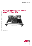
A20 – 6U VMEbus 2eSST Intel® Core™ 2 Duo
CPU Board
n Intel® Core™ 2 Duo L7400
n Core Duo U2500 or L2400
n 1-slot 2eSST VMEbus master and slave
n Up to 4 GB DDR2 DRAM soldered
n 2 SATA, 1 PATA interface
n 1 VGA at front
n 1 Gb Ethernet at front
n 1 USB at front
n 2 XMC or 2 PMC
n PCI Express® six x1 links
n Board controller
The A20 6U single-slot VMEbus SBC supports a variety
of Intel® Core™ Duo and Core 2 Duo processors from
the high-end 1.5 GHz L7400 to the low-voltage dualcore versions down to a selection of single-core
Celeron® M types. It is designed especially for systems
which require high computing and graphics
performance and low power consumption in a typical
Windows® environment, under VxWorks® or Linux.
Using the TSI148 bridge controller the CPU card
provides 2eSST performance levels while maintaining
backwards compatibility with older standards such as
VME64 and VME32.
The standard I/O available at the front panel of the A20
includes graphics on a VGA connector, one Gigabit
Ethernet and one USB 2.0 interface. As an option a
COM interface on an RJ45 connector can be provided
instead of the USB interface.
As rear I/O the A20 provides seven USB interfaces, one
SATA port and PMC rear I/O.
A second SATA interface for connection of an onboard
hard disk or for building up RAID systems is provided
on-board instead of one PMC or XMC. One PATA
interface supports the onboard CompactFlash® slot.
The working memory comprises up to 4 GB DDR2
DRAM which is soldered to guarantee optimum shock
and vibration resistance.
A total of six PCI Express® lanes for high-speed
communication (such as Gb Ethernet) are supported
A20 Data Sheet / 2013-02-06
on the A20. One x1 PCIe® link is used for the onboard Ethernet
interface, three x1 links support the XMC slots, one x1 link supports the
PMC slots via a PCI Express® to PCI-X bridge and one x1 link is used for
connection of the VMEbus bridge. The PMC slots support 64bit/66MHz
(PCI-X).
Supervision of the processor and board temperature as well as a
watchdog for monitoring the operating system complete the
functionality of the SBC.
The A20 comes with a tailored passive heat sink within 4 HP height.
However, forced air cooling is always required inside the system.
Equipped with Intel® components exclusively from the Intel® Embedded
Line, the A20 has a guaranteed minimum standard availability of 5
years.
Its robust design make the A20 especially suited for rugged
environments with regard to extended operating temperature, shock
and vibration according to applicable DIN, EN or IEC industry standards.
It is also ready for coating for use in humid and dusty environments. The
wide range of industrial applications include for example monitoring,
vision and control systems as well as test and measurement. Main target
markets comprise industrial automation, security and infotainment,
traffic and transportation, shipbuilding, medical engineering and
robotics.
Page 1
Embedded Solutions
for Transportation and Industrial Markets
www.men.de/products/01A020-.html
Diagram
A20 Data Sheet / 2013-02-06
Page 2
Embedded Solutions
for Transportation and Industrial Markets
www.men.de/products/01A020-.html
Technical Data
CPU
n
n
Memory
n
n
n
n
n
Mass Storage
n
n
Graphics
n
n
I/O
n
n
Front Connections
n
n
n
Rear I/O
n
n
n
A20 Data Sheet / 2013-02-06
Up to Intel® Core™ 2 Duo L7400
o Dual-core 64-bit processor
o Up to 1.5GHz processor core frequency
o Up to 667MHz front-side bus frequency
Chipset
®
o Northbridge: Intel 945GME Express
®
o Southbridge: Intel ICH7-M DH
4MB L2 cache integrated in Core 2 Duo
Up to 4GB SDRAM system memory
o Soldered
o DDR2
o 667MHz memory bus frequency
o Dual-channel, 2x64 bits
CompactFlash® card interface
o Via onboard IDE
o Type I
o True IDE
o DMA support
8Mbits boot Flash
Serial EEPROM 2kbits for factory settings
Parallel IDE (PATA)
®
o One IDE port for local CompactFlash
Serial ATA (SATA)
o One channel for onboard hard disk
o One channel via rear I/O connector P2
o Transfer rates up to 150MB/s
o RAID level 0/1 support
Integrated in 945GME Express chipset
o 200/250MHz 256-bit graphics core
VGA connector at front panel
USB
o One USB 2.0 port via Series A connector at front panel
o Seven USB 2.0 ports via rear I/O
o UHCI implementation
o Data rates up to 480Mbit/s
Ethernet
o One 10/100/1000Base-T Ethernet channel at front panel
o RJ45 connector at front panel
®
o Ethernet controller connected by one x1 PCIe link
o Onboard LEDs to signal activity status and connection speed
VGA
One USB 2.0 (Series A)
One Ethernet (RJ45)
USB 2.0, seven ports
PMC rear I/O (for one PMC)
One SATA channel
Page 3
Embedded Solutions
for Transportation and Industrial Markets
www.men.de/products/01A020-.html
Technical Data
Mezzanine Slot
n
n
n
Miscellaneous
n
n
n
n
n
n
PCI Express®
n
n
n
n
n
VMEbus
n
n
n
n
n
n
n
n
n
n
n
n
n
n
n
Two slots usable for PMC or XMC
XMC slots
o Compliant with XMC standard VITA 42.3-2006
®
o Two x1 PCI Express links for slot 2
®
o One x1 PCI Express link for slot 1
PMC slots
o Compliant with PMC standard IEEE 1386.1
o PCI / PCI-X 32/64 bit, 33/66MHz, 3.3V V(I/O)
®
®
o One x1 PCI Express link via PCI Express to PCI-X bridge
o PMC I/O module (PIM) support (for one PMC)
o Current limited to 2A for 5V and 3.3V
Board controller
Real-time clock, buffered by a GoldCap and a battery
Watchdog timer
Temperature measurement
One user LED
Reset button
One x1 link to connect local 1000Base-T Ethernet controller
Three x1 links to connect XMC
One x1 link to connect PMC via PCI Express® to PCI-X bridge
One x1 link to connect the VME bridge via a PCI Express® to PCI-X bridge
Data rate up to 250MB/s in each direction (2.5 Gbit/s per lane)
IDT TSI148 controller
Compliant with VME64 Specification
Supports VME32, VME64, 2eVME and 2eSST (VITA 1.5)
Maximum data rate 250 MB/s (limited by PCI Express® link)
Slot-1 function with auto-detection
Master
o D08:D16:D32:D64:A16:A24:A32:A64:BLT:MBLT:RMW
Slave
o D08:D16:D32:D64:A16:A24:A32:A64:BLT:MBLT
DMA
Mailbox functionality
Bus timer
Location Monitor
Interrupter D08(O):I(7-1):ROAK
Interrupt handler D08(O):IH(7-1)
Single level 3 fair requester
Single level 3 arbiter
Electrical Specifications
n
Supply voltage/power consumption:
o +5V (-3%/+5%), 3.2A (idle)..6.6A (full load)
o 3.3V for XMC/PMC are generated on the board
Mechanical Specifications
n
Dimensions: standard double Eurocard, 233.3mm x 160mm
Front panel: 4HP with ejector
Weight:
o Without XMC/PMCs: 525g
n
n
A20 Data Sheet / 2013-02-06
Page 4
Embedded Solutions
for Transportation and Industrial Markets
www.men.de/products/01A020-.html
Technical Data
Environmental Specifications
n
Temperature range (operation):
o 0..+60°C
o Airflow: min. 1.5m/s
Temperature range (storage): -40..+85°C
Relative humidity (operation): max. 95% non-condensing
Relative humidity (storage): max. 95% non-condensing
Altitude: -300m to + 3,000m
Shock: 15g/11ms (EN 60068-2-27)
Bump: 10g/16ms (EN 60068-2-29)
Vibration (sinusoidal): 1g/ 10..150Hz (EN 60068-2-6)
Conformal coating on request
MTBF
n
190,571h @ 40°C according to IEC/TR 62380 (RDF2000)
Safety
n
PCB manufactured with a flammability rating of 94V-0 by UL recognized manufacturers
EMC
n
Tested according to EN 55022 Class A (radio disturbance), EN 61000-4-2 (ESD), EN 61000-4-4 (burst) and
EN 61000-4-5 (surge)
BIOS
n
Award BIOS
Software Support
n
Windows®
Linux
VxWorks®
QNX® (on request)
Intel® Virtualization Technology, allows a platform to run multiple operating systems and applications in
independent partitions; one computer system can function as multiple "virtual" systems
For more information on supported operating system versions and drivers see Downloads.
n
n
n
n
n
n
n
n
n
n
n
n
n
A20 Data Sheet / 2013-02-06
Page 5
Embedded Solutions
for Transportation and Industrial Markets
www.men.de/products/01A020-.html
Configuration & Options
Standard Configurations
Article No.
CPU Type
System RAM
XMC/PMC
P0 Ethernet
Operation Temp.
01A020-00
L7400
2 GB DDR2
2 slots
No
0..+60°C
Options
CPU
n
n
n
n
Memory
n
n
I/O
n
Core 2 Duo L7400, 1.5GHz LV
Core Duo L2400, 1.66GHz LV
Core Duo U2500, 1.2GHz ULV
Celeron® M 423, 1.06 GHz
System RAM
o 512 MB, 1 GB, 2 GB or 4 GB
CompactFlash®
o 0 MB up to maximum available
UART (instead of front USB and one PCI Express® link)
o One RS232 via adapter cable (see Accessories)
o One RJ45 connector at front panel
o Data rates 300bit/s..230kbit/s
o FIFO receive and transmit buffers for high data throughput
o Handshake lines: full support
Please note that some of these options may only be available for large volumes. Please ask our sales staff for more information.
A20 Data Sheet / 2013-02-06
Page 6
Embedded Solutions
for Transportation and Industrial Markets
www.men.de/products/01A020-.html
Ordering Information
Standard A20 Models
01A020-00
Intel® Core™ 2 Duo L7400, 1.5 GHz, 2 GB DDR2 DRAM, P0 not mounted, 0..+60°C
Memory
0751-0045
CompactFlash® card, 4 GB, Type I, fixed bit set, -40..+85°C
0751-0055
CompactFlash® card, 8 GB, Type I, fixed bit set, -40..+85°C
0751-0060
CompactFlash® card, 16 GB, -40..+85°C
0751-0061
CompactFlash® card, 2 GB, Type I, fixed bit set, -40 to +85°C
05F006-00
RS232 interface cable RJ45 to 9-pin D-Sub (1 COM to 1 COM), 2m
05P000-01
25 mounting screw sets to fix PMC/XMC modules on carrier boards
Miscellaneous Accessories
Software: Linux
Software: Windows®
Software: VxWorks®
Software: Firmware/BIOS
This product is designed to work under Linux. See below for all available separate software packages.
13MD05-90
MDIS5 System (and Device Driver) Package (MEN) for Linux. This software package
includes most standard device drivers available from MEN.
13Z014-90
Linux device driver (MEN) for PCI-to-VME bridge on A12, A13, A14, A15, A17, A19, A20,
A21B/A21C and B11
This product is designed to work under Windows®. See below for all available separate software packages.
13F014-77
Windows® Installset (MEN) for F14, F15, F17, F18, D9, D601, A19 and A20
(Includes all free drivers developed by MEN for the supported hardware.)
13T001-70
Windows® network driver (Intel®) for F14, F15, F17, F18, D9, D6, D7, D601, A19, A20
and P601, P602
13T003-70
Windows® chipset driver (Intel®) for F14, F15, F17, F18, F18E, F19P, F21P, F22P, G20,
G22, XM2, CB70C, D9, D6, D7, D601, A19 and A20
13T005-70
Windows® USB2UART driver (FTDI) for F14, F15, F17, F18, F19P, F21P, F22P, F23P, D9,
A19, A20, XM2 and XM50 / XM51 / F50P / F50C hosts
13T007-70
Windows® chipset graphics driver (Intel®) for F15, F17, D9, A19 and A20
13Z014-71
VME4WIN/MDIS5 Software Package (MEN) - VMEbus support under Windows® XP/Vista/
Windows® 7 for MEN A19 and A20
This product is designed to work under VxWorks®. For details regarding supported/unsupported board
functions please refer to the corresponding software data sheets.
10A019-60
VxWorks® 6.6 BSP for A19 and A20
13Y001-06
MDIS5 low-level driver sources (MEN) for LM63 on SMBus for F14, F15, F17, F18, F19P,
D9, D601, A19 and A20
13Y002-06
MDIS5 low-level driver sources (MEN) for F14, F15, F17, F18, D9, D601, A19 and A20
board monitoring
13Y004-06
MDIS5 low-level driver sources (MEN) for generic SMBus driver for F14, F15, F17, F18,
F19P, F21P, F22P, G20, G22, D9, D601, F600 and F601, A19, A20, F217, CB70C, SC24,
BC50M, BC50I and BL50W
13Y007-06
MDIS5 low-level driver sources (MEN) for F14, F15, F17, F18, D9, D601, A19 and A20
board controller
This product includes a specially adapted BIOS.
14A020-00
A20 Data Sheet / 2013-02-06
System BIOS for A19 and A20
Page 7
Embedded Solutions
for Transportation and Industrial Markets
www.men.de/products/01A020-.html
Ordering Information
Software: Miscellaneous
Intel® software development products such as analyzers, compilers, threading tools etc. can be downloaded
under www.intel.com/cd/software/products/asmo-na/eng/index.htm. IA-32 Intel® Architecture Software
Developer's Manuals are available under www.intel.com/products/processor/manuals/index.htm.
For operating systems not mentioned here contact MEN sales.
Documentation
Compare Chart 6U VMEbus CPU and I/O cards » Download
20A020-00
A20 User Manual
20A020-ER
A20 Errata
21APPN016
Application Note: Accessing SMBus under Linux Kernel 3.2 on MEN Intel® Boards
Contact Information
Germany
France
USA
MEN Mikro Elektronik GmbH
Neuwieder Straße 3-7
90411 Nuremberg
Phone +49-911-99 33 5-0
Fax +49-911-99 33 5-901
MEN Mikro Elektronik SAS
18, rue René Cassin
ZA de la Châtelaine
74240 Gaillard
Phone +33 (0) 450-955-312
Fax +33 (0) 450-955-211
MEN Micro Inc.
860 Penllyn Blue Bell Pike
Blue Bell, PA 19422
Phone (215) 542-9575
Fax (215) 542-9577
[email protected]
www.men.de
[email protected]
www.men-france.fr
[email protected]
www.menmicro.com
The date of issue stated in this data sheet refers to the Technical Data only. Changes in ordering information given herein do not affect the date of issue. All brand or product names are
trademarks or registered trademarks of their respective holders.
MEN is not responsible for the results of any actions taken on the basis of information in the publication, nor for any error in or omission from the publication.
MEN expressly disclaims all and any liability and responsibility to any person, whether a reader of the publication or not, in respect of anything, and of the consequences of anything,
done or omitted to be done by any such person in reliance, whether wholly or partially, on the whole or any part of the contents of the publication.
The correct function of MEN products in mission-critical and life-critical applications is limited to the environmental specification given for each product in the technical user manual.The
correct function of MEN products under extended environmental conditions is limited to the individual requirement specification and subsequent validation documents for each product
for the applicable use case and has to be agreed upon in writing by MEN and the customer.Should the customer purchase or use MEN products for any unintended or unauthorized
application, the customer shall indemnify and hold MEN and its officers, employees, subsidiaries, affiliates, and distributors harmless against all claims, costs, damages, and expenses,
and reasonable attorney fees arising out of, directly or indirectly, any claim or personal injury or death associated with such unintended or unauthorized use, even if such claim alleges
that MEN was negligent regarding the design or manufacture of the part.
In no case is MEN liable for the correct function of the technical installation where MEN products are a part of.
Copyright © 2015 MEN Mikro Elektronik GmbH. All rights reserved.
A20 Data Sheet / 2013-02-06
Page 8