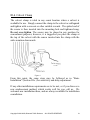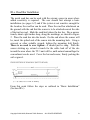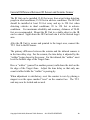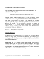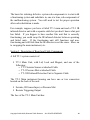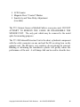
1
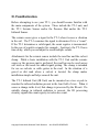
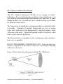
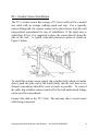
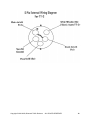
Diamond Traffic Products P. O. Box 1455 76433 Alder Street Oakridge, OR 97463 Traffic Tally-3 Field Unit Instruction Manual Seismic/Infra-Red/Pressure Mat Volume Counter Version 2.00 Revised 10-11-06 Table of Contents I. Introduction............................. 1 I.a. Product Description..... 1 I.b. Battery Life ................. 1 I.c. How To Use This Manual 2 II. Familiarization.................... III. Sensor Installation ............. 4 III.a. Pressure Mat Installation… 4 III.b. Passive Infrared Installation … 5 III.c. Seismic Sensor Installation… 6 III.d. Culvert Clamp ........... 8 III.e. Road Bar Installation. … 9 III.f. General Differences ... 10 Appendix A- Basic Troubleshooting … 11 Appendix B – Failure Identification … 13 Copyright ©1991-2008, Diamond Traffic Products ALL RIGHTS RESERVED ii I. Introduction Thank you for purchasing the Traffic Tally 3 Seismic/Infrared/Pressure Mat Counter. This manual describes the operation and programming of the TT-3 Counter. Please read and understand this manual before attempting operation. I.a. Product Description The TT-3 is a data-gathering instrument designed for use in the field. The extruded welded aluminum case is tough, light, and very weather resistant. Life expectancy of the single, replaceable “C”-sized lithium battery is five years. The unit can operate using a seismic sensor, infrared sensor or a pressure mat detector. The only adjustments required are for sensitivity and time delay. These two adjustments are located on the face of the counter and are made by using a small plastic screwdriver (provided with the counter). The sensitivity is factory set at mid-range that should work for most applications. We recommend you consult with Diamond Traffic before adjusting sensitivity. Resetting the counter display to zero is accomplished by placing a magnet over the area marked “control” on the face of the unit. I.b. Battery Life The TT-3 battery will power the seismic sensors or pressure mat sensor for approximately five years. When using the TT-3/IR the battery life is approximately two years. The “C” cell battery should be replaced at this time. To be sure the watertight seal is maintained, we suggest you send the TT-3 back to the factory for battery replacement. Copyright ©1991-2008, Diamond Traffic Products ALL RIGHTS RESERVED 1 I.c. How To Use This Manual This manual completely describes the installation/operation of the TT-3 and all attachments. Section II Familiarization of the TT-3 Unit and attachments Section III Sensor Installation Appendix A Some basic installation trouble-shooting procedures Appendix B For in-depth troubleshooting Copyright ©1991-2008, Diamond Traffic Products ALL RIGHTS RESERVED 2 II. Familiarization Before attempting to use your TT-3, you should become familiar with the main components of the system. These include the TT-3 unit, and the TT-3 Seismic Sensor and/or the Pressure Mat and/or the TT-3 Infrared Sensor. The seismic sensor gives a signal to the TT-3 when it senses a vibration in the soil. The TT-3 examines the signal to determine if it is a “count”. If the TT-3 determines a valid signal, the count register is incremented. In the case of repetitive signals (for example – footsteps), the TT-3 has a time-delay, which you can adjust to avoid multiple counts. Attachments for the seismic sensor include the road bar and the culvert clamp. While a basic installation with the TT-3 Unit and the seismic sensor or the pressure mat is preferred, the road bar can be used across soft trails or dirt roads for added signal pickup. The clamp is intended for use on culverts or cattle grates in the road. In the situation of a gravel or dirt road where a culvert is located, the clamp makes installation simple and helps conceal the unit. The TT-3 Infrared Unit (IR Unit) can be mounted on a tree or pole to monitor the infrared radiation present in the lens field of view. When it senses a change in the level, that change is processed by the IR unit. If a suitable change in infrared radiation is present, the IR processing circuitry signals the count registry to index one count. Copyright ©1991-2008, Diamond Traffic Products ALL RIGHTS RESERVED 3 III. Sensor Installation Ideal conditions are dirt or gravel roads, hiking trails, or any other location where a bulk count is desired. The only materials normally required are a small, plastic, flat-blade screwdriver for sensitivity and time-delay adjustment, a magnet for reset, a shovel and pick if burying a sensor plus the TT-3 and any optional materials or tools that will aid installation. III.a. Pressure Mat Installation The pressure mat sensor is easy to install and works well in all weather conditions. To install the pressure mat sensor you will need a shovel, maybe a pick and a bag of sand. Dig a trench about 4 feet wide, 4-6 inches deep, and 6 inches longer than the pressure mat across the trail. Remove any rocks and roots so the trench bottom is a fine soil or sand bed. Lay a bed of sand, then lay the pressure mat in trench and cover with soil or trail material. Dig a narrow 9 foot long trench from the mat area to the specified counter location (optional conduit can be used to protect the lead-in cable). Attach 5-pin connector cable end to TT-3 input and adjust sensitivity pot to about the 12:00 position <pointing straight up> and set the delay to the quarter till position (pointing to the left). Walk on the mat to make sure you get a count before completely burying mat and cable. Note: If counter does not count, try turning sensitivity up further. If counter double counts, try turning the delay up further (see section III.c. for further explanation on sensitivity and delay adjustments). Once you have verified counter is advancing, bury the mat and cable leading up to the counter. Copyright ©1991-2008, Diamond Traffic Products ALL RIGHTS RESERVED 4 III.b. Passive Infrared Installation The TT-3 Infrared attachment (TT-3IR) is an example of today’s technology. Passive infrared needs no reflector since a light beam is not used. Instead it monitors background radiation level and looks for quick changes in this level. It is relatively easy to install, as long as you follow the guidelines listed below. The Target Area (a) should have a background that is as thermally stable as possible. Examples of unstable backgrounds are river or stream water, trails with roads in the background (b), and leafy bushes, which will move in the wind. A good back ground would be solid trees, a dirt bank, or other non-moving feature. The Detection Zone (c) should be as free of intrusions such as branches, leaves, etc. as possible. DO NOT DISASSEMBLE THE SENSING UNIT. There are some very sensitive components in the interior of the unit, and improper handling will destroy the device. Figure 3 below shows the detection area for the TT-3 IR Sensor. ______________35’ maximum range________________________ Target Area – 5’ diameter at 35’ distance from lens 2’6” diameter at 25’ distance from lens Figure 3 Copyright ©1991-2008, Diamond Traffic Products ALL RIGHTS RESERVED 5 III.c. Seismic Sensor Installation The TT-3 seismic sensor has a range of 15 feet in soft soil for a normal size adult with an average walking speed and step. For a typically narrow hiking trail, the seismic sensor can be placed away from the trail using natural concealment for ease of installation. If the target area is wider than 10 feet, it is suggested to place the sensor directly along the side of the trail. A typical wide-trail placement option is shown in Figure 1 below. To install the seismic sensor simply dig a shallow hole (about six inches down), push the spike end of the sensor firmly into the soil, then cover. Natural concealment should be used as much as possible. To conceal the cable, dig a shallow narrow trench off of the trail until natural foliage can be used for concealment. Connect the cable to the TT-3 Unit. The unit may show several counts while being connected. Copyright ©1991-2008, Diamond Traffic Products ALL RIGHTS RESERVED 6 To adjust time delay, have a “walker” walk down the trail on the side nearest the sensor. Adjust the time delay so that only one count is tallied while the “walker” is passing by. However, be aware that a long delay may cause the TT-3 to not count close following hikers. When adjustment is satisfactory, reset the counter to zero by placing the magnet over the space marked “reset” on the counter face. The TT-3 unit may now be locked and secured. Copyright ©1991-2008, Diamond Traffic Products ALL RIGHTS RESERVED 7 III.d. Culvert Clamp The culvert clamp is ideal in any count location where a culvert is available for use. Simply connect the clamp to the culvert or cattleguard and tighten with a crescent or other suitable wrench. The spiked end of the sensor is then inserted into the mounting hole and tightened snug. Do not over-tighten. The sensor may be placed in any position for concealment purposes; however, it is suggested you place the clamp at the top of the culvert with the sensor inserted into the clamp with the spike pointing downwards. Figure 4 From this point, the same steps may be followed as in “Basic Installation” (Section III.c.) for sensitivity and delay adjustment. If any other installation requirements are to be met, or if you discover a new emplacement method, which works well for you, call us. We welcome new installation ideas, and are always available for installation consultation. Copyright ©1991-2008, Diamond Traffic Products ALL RIGHTS RESERVED 8 III.e. Road Bar Installation The metal road bar can be used with the seismic sensor in areas where added sensitivity is required. The user should first attempt a basic installation (see pages 6-7) and if the system is not sensitive enough for the location, the road bar can be used. Place the road bar attachment on the ground with the end that the sensor is to be attached nearest the side of the trail or road. Mark the road/trail where the bar lies. Dig a narrow trench, about eight inches deep, along the markings, as shown in Figure 2. Place the road bar into the trench. On the end where the sensor will be, insert the spiked end of the sensor into the mounting hole. Using a crescent or other suitable wrench, tighten the mounting bolt firmly. There is no need to over tighten—it should just be snug. With the sensor sticking up, extend a trench for the cable lead off of the site toward the area where the TT-3 unit will be, until natural camouflage for concealment can be used. Cover the bar and sensor, firmly packing the soil or gravel. From this point follow the steps as outlined in “Basic Installation” (Section III.c.) Copyright ©1991-2008, Diamond Traffic Products ALL RIGHTS RESERVED 9 General Difference Between IR Sensor and Seismic Sensor The IR Unit can be installed 15-80 feet away from a trail when detecting people in ideal conditions; 15-50 feet in adverse conditions. The IR Unit should be installed at least 20 feet away and up to 250 feet when detecting vehicles in ideal conditions; 20 to 150 feet in adverse conditions. For maximum reliability and accuracy, distances of 20-80 feet are recommended. Mount the IR Unit to a stable object so the IR can be aimed. Sight down the IR Unit and aim it at the desired target area. After the IR Unit is secure and pointed to the target area, connect the TT-3 Unit to the IR Sensor. The primary difference between the seismic and the infrared sensors is in the time delay step. For the seismic, the time delay is adjusted by the “walker” being closest to the sensor. For the infrared, the “walker” must be at the farthest edge of the Target Zone. Have a “walker” (yourself or another person) walk down the trail on the far edge of the Target Zone. Adjust the time delay so that only one count is tallied while the “walker” is passing by. When adjustment is satisfactory, reset the counter to zero by placing a magnet over the space marked “reset” on the counter face. The TT-3 unit may now be locked and secured. Copyright ©1991-2008, Diamond Traffic Products ALL RIGHTS RESERVED 10 Appendix A – Basic Troubleshooting You’ve Installed the System and It Doesn’t Work! Listed below are some common problems and solutions with installations of the TT-3 Unit and attachments. It does not cover failed component possibilities. They are covered in Appendix B. If you meet a situation which is not covered and you find a new solution, or if you have a problem and cannot find a solution, call Diamond Traffic Products for information (541 782-3903) between the hours of 8am and 4pm, Mon-Fri, PST. LCD display does not come on. Call DTP for battery replacement procedure. Counter will not count. Check all connections, check sensitivity and time delay levels (sensitivity should be at maximum to test a units’ response). Counter won’t stop counting It might be that the sensitivity setting is too high and needs to be turned down. In the case of the infrared sensor, there might be too much background thermal noise in the target area. Check for moving brush, which could reflect sunlight, running water, or other reflective disturbances in the background. Check for nearby power lines, which put electrical noise into the cables. For the seismic sensor, check for background vibration such as nearby train tracks, highways or repetitive mechanical equipment such as motors, airconditioners, or swaying trees and bushes. To adjust sensitivity on the TT-3, locate the circular dial on the face plate, insert a small screw driver or pot knife and turn the sensitivity dial (located on the faceplate) clockwise to increase or Copyright ©1991-2008, Diamond Traffic Products ALL RIGHTS RESERVED 11 Counter-clockwise to decrease. (Note: Later versions of the TT-3 have a precision pot which has four 360 degree revolutions between minimum and maximum). Counter counts twice Time delay needs to be increased. If the time delay is at maximum, try moving the seismic sensor farther away from the site. In the case of the IR (infrared) sensor, it might need to be moved away from the target zone to provide a thermally stable background. • Counter over counts Time delay needs to be increased (Note: adjustment located on the face of the counter—four 360 degree revolutions to attain maximum setting on newer versions of the TT-3). If it is at maximum try moving the seismic sensor farther away from the site. In the case of the IR sensor, it might need to be moved away from the target zone to provide a thermally stable background. Copyright ©1991-2008, Diamond Traffic Products ALL RIGHTS RESERVED 12 Appendix B-Failure Identification This appendix is for identification of a failed component or cable in the TT-3 System. IMPORTANT WARRANTY INFORMATION Diamond Traffic Products requires any TT-3 Unit or Optional Sensor which malfunctions during its FACTORY WARRANTY PERIOD to be sent back to the factory for repairs. This appendix is provided expressively for the purpose of identifying failed components, and is not intended for repairs. If you attempt or perform any repair or disassembly on a TT-3 Unit or Optional Sensor which is still covered under a factory warranty, YOU WILL VOID ANY WARRANTY EITHER EXPRESS OR IMPLIED. Section 1. Description of Components Test Unit Definition In order to test any component of a TT-3 system, you will need what is known as a “Test Unit”. A test unit is a component that is known to be working perfectly which you can use to help identify the exact problem with another component. When testing the TT-3 Seismic System, some cautions must be taken. Vibratory motion in the area, such as an air-conditioner or even a computer fan will have an effect on any tests attempted. For the TT-3 Infrared Sensor, background thermal noise such as a window or a heater will also have a detrimental effect on testing. Copyright ©1991-2008, Diamond Traffic Products ALL RIGHTS RESERVED 13 The basis for isolating defective system sub-components is to start with a functioning system and substitute in, one at a time, sub-components of the malfunctioning system. You will need to test for proper operation after each substitution is made. For example, suppose you have a failed TT-3 main unit and a TT-3 IR infrared detector unit with a separate cable but you don’t know what part has failed. If you happen to have another like unit that is correctly functioning, you could swap the IR infrared detector between operating and failed units. If the functioning unit still functions and nonfunctioning unit still fails then the IR detector is not the cause. Move on to swapping the main instrument, etc Section I. Description of Board and Cable Components A full TT-3 system consists of: TT-3 Main Unit, with Lid, Lock and Magnet, and one of the following: o TT-3 Seismic Sensor w/attached Cable o TT-3 Pressure Mat w/attached Cable o TT-3 IR Infrared Detection Unit w/Separate Cable The TT-3 Main instrument housing can have one or two connectors located on the back of the unit: Seismic, IR Sensor Input, or Pressure Mat Remote Triggering Output The face of the TT-3 Main Unit has: Copyright ©1991-2008, Diamond Traffic Products ALL RIGHTS RESERVED 14 LCD Counter Magnetic Reset “Control” Marker Sensitivity and Time-Delay Adjustment (two dials) The TT-3 Seismic Sensor w/Molded Cable is a one-piece unit. DO NOT ATTEMPT TO REMOVE THE CABLE OR DISASSEMBLE THE SENSOR UNIT. The only part which may be removed is the metal spike for mounting purposes. The TT-3 IR Infrared Detection Unit is the short, cylindrical component with the cable connector on one end and the IR receiving lens on the opposite end. The IR lens is very sensitive; do not attempt its removal. Bending or deforming the transmissive plastic will greatly reduce the performance of the unit. A soft damp cloth can be used to clean the lens. Copyright ©1991-2008, Diamond Traffic Products ALL RIGHTS RESERVED 15 Copyright ©1991-2008, Diamond Traffic Products ALL RIGHTS RESERVED 16