1
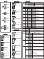
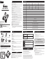
Part Description
Connecting with Computer
1
Corner Holders
Front
Open the connector cover
Open the cover of the USB connector
(MiniB).
LCD
Connect the USB cable
Insert the USB connector (MiniB) end of the
provided USB cable.
USB Connector (MiniB)
3
Connect with your computer
Connect the USB TYPE-A end of the provided
USB cable with the USB port on your
computer.
Tapped holes for
attachment plates
Battery Chamber Cover
4
Communicate with your computer
Transfer data to your G-men software installed
computer.
Battery
Chamber
AA Alkaline
Batteries (LR6 x2)
付属ネジ
1
2
3
1
Be aware of the mounting direction
See how the attachment plate is mounted as
shown in the sketch.
2
3
Do the same with the other side
Mount each attachment plate to the both sides
of the body.
4
Close the battery chamber cover
Put back the battery chamber cover and
tighten the screw securely.
Response Frequency
1M is displayed when the recording interval is 1 minute
Display
Display When Trace Mode is On
10msec
100Hz
Alternately displayed
5msec
100Hz
Alternately displayed
〃
40Hz
Alternately displayed
〃
20Hz
Alternately displayed
2msec
100Hz
Alternately displayed
〃
70Hz
Alternately displayed
〃
45Hz
Alternately displayed
〃
25Hz
Alternately displayed
1msec
100Hz
Alternately displayed
〃
70Hz
Alternately displayed
〃
45Hz
Alternately displayed
〃
25Hz
Alternately displayed
Display during
measurement
is displayed to show that the threshold has been set.
Trigger standing by
,
Trigger measurement
in progress
Warnings
Fix the unit to an object to be
measured.
Install the unit by securing the Attachemnt
Plates using appropriate screws onto an
object to be measured.
are alternately displayed during measurement
Warning and measurement conditions are alternately displayed
Battery is low
Recording stopped
Excess over the threshold is detected when the option is turned “ON”.
Excess over the threshold is measured (displayed for 1 second).
Displayed after 1,000 hazard recordings,and then measurement is halted.
Idling time
Counts down for 5 seconds.
Magnet trigger
Standing by for magnet start
Stopping
Display Options
and
Data capacity is full
Excess over
threshold detected
Excess over
threshold measured
Hazard measurement
ends
Starting
are alternately displayed. The threshold triggers the trace mode to stand by
Triggered to start measuring and
Preset
Install the AA Alkaline Batteries(LR6*2)
correctly as indicated with +/−.
4
10m indicates the sampling cycle
Alternately displayed
Remove the battery chamber cover
Putting in the batteries
Recording Interval 1 Second
Sampling 10 ms and the temperature and humidity are alternately displayed.
100Hz
Mount one of the attachment plates.
Tighten the screw with a screwdriver to fix the
attachment plate on one side of the body.
Make it ready for putting in the batteries.
DR01・DR20
20msec
Open the battery chamber cover
【+】Loosen the screw with a screw driver.
Description
Recording Interval 1 Second
Sampling 10 ms and the temperature and humidity are alternately displayed.
Threshold Setting
How to mount Attachment Plates
How to Install Batteries
Display Sample
DR100
1S indicates the recording interval is 1 second
Sampling Cycle
2
Back
Default Setting
Model
Sampling Cycle and the Response Frequency
3-Axis Direction
Symbol
Base
LCD Display
Display Setting
,
are alternately displayed. The preset starting date and time is shown
(the example at left indicates the 31st at 12:30).
Measurement is suspended.
00
Standard operation Measurement conditions・Temperature and humidity
01
Displays the acceleration of X and Y axes.
02
ID number and the acceleration of Z axis.
03
"Alternately displays maximum measurement axis and the date and time
of acceleration to date
(10 G on Z axis on August 28th at 14:11)"
04
Displays the current number of records
05
Displays the date and time. March 30th 16:20