1
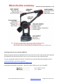
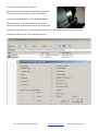
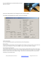
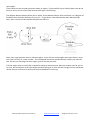
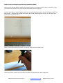
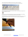
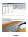
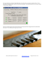
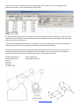
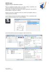
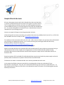
Simple MicroScribe tests All users have great success with their MicroScribe, then one day there is a panic as the dimensions do not seem to be right or it wont connect. This is usually down to the fact you have not made a good connection, set the HOME correctly, or you have forgot to start with the standard tip etc., or you have dropped it or knocked it over. MicroScribes do have a reputation for just working forever. Here are a couple of things to check by going back to basics. If these things do not seem to resolve your problem then we can probably help if you call us, or if all else fails RevWare are there to help as well. http://www.revware.net/ First make sure the connection with your PC is OK. USB is hard to faulter, but you may have reformatted your hard drive or deleted the driver, so it is worth checking by installing the MicroScribe Utlitiy Software (MUS). We have a copy here:‐ http://www.patrick‐thorn.com/docs/scan/MUS_5.1.zip Note you may have to Uninstall first before installing again. With G series MicroScribes the standard USB cable should work Ok, but we do not recommend using a USB extension hub as there maybe not enough power to drive the MicroScribe without loosing positional data. M series MicroScribes require both the power supply and the USB cable without an extension hub. Serial connection of G2 and older 3D (red) MicroScribes need to have both the power supply and serial (RS232) cable connected as no power is derived from the RS232 lead. Full details are shown in the MicroScribe User manual provided with each unit. In the notes that follow, these are provided as a simple guide to help you understand if your MicroScribe is working OK. They are not a method of confirming any accuracy or calibration test. To help understand the notes we will refer to the MicroScribe parts as shown in the following MicroScribe Anatomy illustration. Notes provided by Patrick Thorn & Co www.patrick‐thorn.co.uk info@ patrick‐thorn.co.uk Checking all the axis are working. (MSTest) Before testing for positional repeatability check you have the correct stylus tip that was originally provided with the MicroScribe when new, as this is what the unit was calibrated with. On your original MicroScribe disk there is a MSTest.exe utility for MicroSoft Windows (32 bit). If you cannot find it, we have a copy here. http://www.patrick‐thorn.com/docs/scan/MSTest.zip Download it and UnZip it to a folder. There are 2 parts “MSTest.exe” and “Armdll32” Notes provided by Patrick Thorn & Co www.patrick‐thorn.co.uk info@ patrick‐thorn.co.uk Connect your MicroScribe to your PC. Make sure you have the Stylus Standard Tip installed firmly and the Stylus Holder is clean from debris. Place the Stylus Standard Tip into the Stylus Holder. Make sure there is no debris between the counter balance and the underneath of the Stylus holder block. Position the MicroScribe in a position similar as shown in the MicroScribe Anatomy illustration. Launch the “MSTest.exe” and it will look like this. Notes provided by Patrick Thorn & Co www.patrick‐thorn.co.uk info@ patrick‐thorn.co.uk Press the HOME button on the MicroScribe so the red light turns to green. Now on the “MicroScribe Test Tool” dialog click on the “Connect” button. The window should populate with numbers, similar to this example. Product information This is the information stored on your MicroScribe and is self explanatory. Button Status If you are using the Hand Pager of Twin foot pedal, when clicking or pressing the left or right switch this will be shown as Button 1 or 2 with UP or DOWN. So you can see if your switch is working. Stylus Position and Orientation These numbers flicker about as the position is being constantly calculated for the position of the Stylus and the vector direction it is pointing. If you move the MicroScribe these will change, even the slightest breath or vibration will see the numbers change. The units are in inches and are here so you can see movement, not to measure with. Notes provided by Patrick Thorn & Co www.patrick‐thorn.co.uk info@ patrick‐thorn.co.uk Joint Angles These values are the encoder positions shown as angles. If you carefully try to hold the parts you do not want to move, you can then check and see each part is functioning. The diagram below indicates which part is which. As the MicroScribe we have used here is a 5 degrees of freedom, then the Stylus Roll here is set to “0”. If you have a 6 axis MicroScribe and a MicroScan3D laser, then it is best to take the MicroScan3D unit off first. Note, then angle positions have a reference point, so you will see some angles count up or down, say to zero, then roll over to a new number. This all depends on where the MicroScribe is when you start the test. We are not checking the exact angles, just to see they all move. If all the angles seem to move OK, it should be ready to continue work. We have another test for you to try next, but should one of the joint angles not be working at all, then you will not get correct coordinate results and you will have to return your unit to RevWare for servicing. Notes provided by Patrick Thorn & Co www.patrick‐thorn.co.uk info@ patrick‐thorn.co.uk Simple test for checking the approximate repeatability.(MUS) Now to check the MicroScribe repeats to a known position you need to have a point to measure. Also you need to be careful not to move the MicroScibe base when doing this. Here we have taken a piece of plastic and made a small indentation with a pointed instrument, NOT the MicroScribe. We have then double sided taped this to the desk, along with a steel rule. We have put peincil lines so you can see it.. Make sure you MicroScibe is position so you can reach the plastic hole easily Place the tip back in the Stylus tip holder and Home the MicroScribe. (Green light ON) Notes provided by Patrick Thorn & Co www.patrick‐thorn.co.uk info@ patrick‐thorn.co.uk Launch the MicroScribe Utility (MUS) from the Start menu > Programs > Immersion. If its connected you will see X Y Z values and they will change if you move the MicroScribe. Now we are going to Excel or Notepad to record some numbers. So click the format string button and choose the application you will use. We used Excel and moved the MicroScribe Stylus to the point in our piece of plastic, then clicked the hand pager button once. Then returned the Stylus tip back to its Stylus tip holder. Then we picked the Stylus up again and repeated the same process to measure another point. Note you can change the angle that you place the tip in the hole, but as it is only plastic you may get some variation. Notes provided by Patrick Thorn & Co www.patrick‐thorn.co.uk info@ patrick‐thorn.co.uk Here are our results after 12 measurements. Obviously you will se some deviation in the numbers as this is not a precise test, but it is a good indication that your MicroScibe is working correctly. Checking a known distance (MUS) Here we can use our steel rule, although anything with known increments will be sufficient to give you an indication that the MicroScribe is working. Notes provided by Patrick Thorn & Co www.patrick‐thorn.co.uk info@ patrick‐thorn.co.uk First you need to set a Custom Origin Reference Frame for where you want to measure from. This is described in the MUS Help is you are unsure of the procedure. We used the points on the rule as shown in the previous diagram.. Next we used Excel again and moved the Microscribe tip to positions along the steel rule and clicked each point. This made up picture gives you an idea. Notes provided by Patrick Thorn & Co www.patrick‐thorn.co.uk info@ patrick‐thorn.co.uk Here are our results. Considering we are trying to align to the marks on the rule, we get a clear indication that the X values are recording every 10mm. As mentioned all along, these are simple test to check the MicroScribe is functioning. There are not a substitute for the precision calibration equipment that RevWare use what setting and calibrating each unit at the time of manufacture. If you have checked you MicroScribe is working OK, but it is not working with some other third party software, please check the set up procedure they provided with the software. Should you need to send a MicroScribe back to RevWare, please contact then first, as they will not accept returned items without a valid RMA reference number. Also in any communication please include the Serial number of your MicroScribe which is on the base of the unit. Revware Systems Inc. www.revware.net 2355 Paragon Drive [email protected] Suite E San Jose California CA 95131 USA Notes provided by Patrick Thorn & Co www.patrick‐thorn.co.uk info@ patrick‐thorn.co.uk