1
ATARI 1450XL HOME COMPUTER INTEGRAL DISK DRIVE
SPECIFICATION#
WPSSPL Version 2.8.5 Spooling device DRB1: June 19, 1984 02:25 PM Atari, Inc. Printing
document:
INTEGRAL DISK DRIVE SPEC prelim - ATARI 1450XL HOME
COMPUTER INTEGRAL DISK DRIVE SPECIFICATION#
C062063 - Preliminary
Table of Contents
• ATARI 1450XL HOME COMPUTER INTEGRAL DISK DRIVE SPECIFICATION
• INTEGRAL DISK DRIVE SPEC prelim - ATARI 1450XL HOME COMPUTER INTEGRAL DISK
DRIVE SPECIFICATION
FIGURES:
5.01 - ATARI 1450XL Home Computer (3/4 view) 5.02 - Integral Disk Drive Mechanical Details
1.0 INTRODUCTION
This document details the engineering design specifications for the integral Disk Drive of the
ATARI 1450XL Home Compu- ter. It is the major information transfer document for the transfer
of information from the Hardware and Software Devel- opment groups to Manufacturing, Design
Assurance, and Appli- cations Software organizations. It covers all aspects of the Disk Drive either
directly or indirectly by reference to ap- plicable documents.
2.0 RELEVANT DOCUMENTS
•
•
•
•
•
•
•
•
ATARI 600XL Home Computer Product Specification - C061611
ATARI Single Density Floppy Diskette Specification - C016884
ATARI Double Density Floppy Diskette Specification - C016890
ATARI 1050 Disk Drive Specification - C061272
ATARI Personal Computer System, Operating System User's Manual
Tandon TM50-2 Product Specification and User's Manual
Parallel Bus Interface (PBI) Specification - C061902
ATARI SIO Specification - 81-PS-0602
3.0 VERVIEW
The ATARI 1450XL Home Computer Integral Disk Drive shall be a rotating disk memory designed
for random access data entry, storage, and retrieval applications. Typical applications include storing
programs and data, and loading programs into the system.
The drive shall be capable of reading both sides of a diskette in single density or double density
formats, at the user's discretion.
4. PERFORMANCE
4.1 Environmental
4.1.1 Temperature
Operating (media dependent) -- 10 degrees C to 46 degrees C (50 degrees F to 115 degrees F)
Non operating -- -40 degrees C to 71 degrees C (-40 degrees F to 160 degrees)
4.1.2 Relative Humidity
Operating, noncondensing (media dependent) -- 20 to 80 percent
Nonoperating, noncondensing -- 5 to 85 percent
4.1.3 Altitude
152.4-meters (500-feet) below sea level to 15,240-meters (50,000-feet) above sea level.
4.2 Endurance Levels
The Integral Disk Drive shall use ANSI compatible 5-1/4 inch diskettes with a media life (for reference
only) of 4x10^6 passes per track. The drive shall format diskettes with 40 tracks, single density, and
80 tracks, double density. There shall be a track spacing of 0.529-millimeters (20.8 milinches).
The drive head life shall be 20,000 media contact hours.
The disk rotational speed shall be 288 RPM (plus or minus 1.5 percent). There shall be an average
rotational latency of 104 milliseconds, with an instantaneous speed variation (ISV) of plus or minus 3percent.
The motor start time shall be 1-second, maximum.
The seek time, track to track, shall be 20 milliseconds. The head settling time shall be 20
milliseconds, with an average track access time (including head settling time) of 287-milliseconds <?
>.
The recording mode is FM (Single Density) and MFM (double density).
The data transfer rate shall be 250,000 bits per second, double density.
Flux reversals per inch (FRPI) on the inside track shall be 5,535 for side 0 and 5,877 for side 1.
The unformatted recording capacity shall be 520,800 bytes per diskette.
4.3 Reliability
4.3.1 Error Rates
Exclusive of external sources, such as electronic equipment, and defective or contaminated
diskettes.
• Recoverable soft errors -- 1/10^9 bits
• Recoverable hard errors -- 1/10^12 bits
• Seek Errors -- 1/10^6 seeks
4.3.2 MTBF and MTTR
• MTBF -- 8,000 hours, 25 percent duty cycle
• MTTR -- 30 minutes
(These are Tandon's figures)
4.4 Compliances
UL for power???? UL for fan????
4.5 Electrical Performance
+12-volts DC plus or minus 0.6-volt, 1.3 amperes, maximum, surge for 50 mulliseconds, 800
milliamps average.
+5 volts DC plus or minus 0.25 volt at 800 milliamps, maximum, with less than 100 millivolts peak-topeak ripple.
5 INTERFACE SPECIFICATIONS
5.1 Package and Appearance
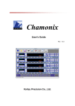
The ATARI 1450XL Home Computer Integral Disk Drive will be a low profile that will be installed at
the top right of the computer console (see Figure 5.01). An activity indicator <LED?>, located on the
front panel is to be automatically illuminated when the drive is selected.
User access for diskette loading will be via an horizontal slot at the front of the drive. The diskette will
be locked into place by a front latch.
5.2 Electromechanical Subassemblies
5.2.1 Functional Description
When the user inserts a diskette into the drive, it will be held in place by aluminum guard rails.
The diskette will slide into the drive until a back stop is encountered, which will latch the ejection
mechanism.
Closing the front latch will activate the cone clamping mechanism, which will accurately center the
diskette and clamp it into place. The drive hub is held to a constant rotation of 288-RPM by a servocontrolled DC motor. The heads will remain in contact with the diskette until the front latch is opened.
The drive heads will be positioned over the desired track by means of a 4-phase stepper motor-band
assembly and associated electronics. The positioner will use a one step rotation to cause a one track
linear movement.
When the front latch is opened, the cone clamping mechanism will raise, allowing for the free exit of
the diskette. The eject mechanism will then unlatch and force the diskette part way out of the drive.
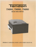
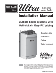
5.2.2 Mechanical Details
Refer to Figure 5.02.
The drive will have a Track 0 sensor, which will detect when the Head-Carriage Assembly is
positioned Track 0 on the diskette. It will also have a write protect sensor which will disable the write
electronics when a tab covers the write protect notch on the diskette.
The drive spindle will be belt driven by a DC motor which will contain an integral tachometer. The
servo control circuit and tachometer will control the speed of the spindle.
The Read/Write Head Assembly will be positioned by a split band positioner mounted to a stepper
motor. The read/write heads will be glass bonded ferrite ceramic structures and have a life
expectancy of 20,000 operating hours.
The electronic components will be mounted on two printed circuit boards. The logic circuit board is to
be mounted above the chassis. The motor control circuit board is to be mounted on the bottom of the
chassis.
5.2.3 Power and Interface Signals
Power and the interface signals are to be routed through two 23-pin connectors which will plug
directly into the CPU board. The connectors will mate directly with the circuit board connectors at the
rear of the drive.
The first connector is for Drive 1; the second is for Drive 2. The pin assignments are as follows:
{table} 1-4 | Write Protect 5-7 | Diskette Enable 8-11 | Track 0 Sensor 12-17 | Stepper Motor Control
18-21 | Spindle Motor Control 22-23 | Disk Activity Light {table}
5.2.4 Cooling Fan
A ??-inch cooling fan shall be placed on the rear of the disk drive. It shall draw +12-volts, 0.15-a from
<?????>.
FIGURE 5.01 -- ATARI 1450XL Home Computer (3/4 view)
FIGURE 5.02 -- Integral Disk Drive Mechanical Details 6. SOFTWARE EXTERNAL REFERENCE
SPECIFICATION
This section is a copy of the SOFTWARE EXTERNAL REFERENCE SPECIFICATION prepared
by HCD Software Engineering, dated 5/20/83. It has been renumbered from the original to match
this document. References to the computer have also been changed for consistency throughout this
document.
6.1 Purpose
6.1.1 Introduction and Product Description
This document is the reference specification for the software interfaces to be used by applications
programs and the operating system to control the Integral Disk(s).
The Integral Disk Drive is a built-in peripheral which connects to the ATARI 1450XL Home Computer
by means of the Parallel Bus Interface (PBI).
The integral disk drive is capable of operating in two "size" modes. For the sake of clarity within this
document, these modes will be referred to as "large" and "small" mode. The "large" mode addresses
the disk as a single logical entity, with two physical sides. The "small" mode addresses the disk as
two logical entities, one per physical side of the disk.
The Integral Disk Handler is responsible for all physical accesses to the integral disk. The unit of data
transfer for this handler is a single disk sector containing 128 bytes of data.
6.1.2 Consumer Profile
The user of this product will be the disk handler contained within the operating system and within
DOS/FMS.
6.1.3 Interface With Other Products
The Integral Disk Handler is an input/output peripheral, performing no actions without instructions
from an applications program.
Applications programs will access the Integral Disk Driver indirectly through CIO or through PIO/SIO
calls.
The Integral Disk Drive uses COMMAND BYTE $B1 and $B2 for internal use. These COMMAND
BYTES may not be used by any other drivers.
6.1.4 Family of Products
The Integral Disk Handler belongs to the Systems family of products.
6.2 Applicable Documents
• "'SURELY' External Reference Specification, Revision 2", Scott Scheiman, Rick Nordin, 4/8/83
• "1050 Disk Drive Product Specification", George Nishiura, Atari Part Number CO61272,dated
3/8/83.
• "ATARI Personal Computer System, Operating System, User's Manual", November 1980.
6.3 Requirements
6.3.1 Interfaces
6.3.1.1 Physical Requirements
The Integral Disk Driver shall masked into 2K bytes ($D800-$DFFF) on the 1450 CPU board.
On power-up, the 1450 will apply power to the disk drive(s) only if the door to drive 1 is open. The
disk driver shall display an informational message (wording TBD) to the user directing him to insert
a disk in drive 1 and shut the door. Upon closing the door to drive 1, the driver shall perform a disk
boot.
6.3.1.2 Logical Requirements
The driver shall be switched into the floating point address space of the Operating System, when
required by the Operating System.
The driver shall use RAM for input and output buffers, variables for communicating with the user, and
internal variables. Internal variables shall be in TBD, permanently allocated in the OS database for
use by this driver.
User communication variables shall be the system DCB.
The default mode of the integral disk shall be "small" mode - two logical sides per disk. All parallel
devices in the system must be in the same mode. The SET MODE command shall be used to
change the mode and all parallel devices shall change mode at the same time.
6.3.1.3 Man/Machine Interface
During a COLD START, the driver will initialize the disks to "small" mode. During WARM START, the
driver will determine the current mode and will maintain that mode.
6.3.2 Functional Description
6.3.2.1 Device Control Block
Communication between the Integral Disk Driver and the disk handler shall be by means of the
system DCB. The DCB is be 12 bytes long. The disk handler must supply the required DCB
parameters and execute a JSR to SIOV $E459.
DEVICE ID (DDEVIC $0300) - Device ID for the disk drives shall be $31. This parameter is set up by
the handler.
DEVICE NUMBER (DUNIT $0301) - Disk drive number to be accessed (1-icon_cool.gif. This
parameter is set up by the handler.
COMMAND BYTE (DCOMND $0302) - Disk drive command to be performed (see para. 3.2.2). This
parameter is set up by the handler, or by the user, if the user calls PIO/SIO directly.
STATUS BYTE (DSTATS $0303) - Indicates to PIO what to do after the command frame is sent and
acknowledged. This parameter is set up by the handler. Valid codes are:
• $00 - No data transfer is associated with the operation
• $40 - A data frame is expected from the disk
• $80 - A data frame is to be sent to the device.
- Indicates status of the command upon return to the handler. This parameter is set up by the driver.
Possible status codes are:
•
•
•
•
•
•
$01 - Operation complete, no errors
$80 - BREAK key abort
$8A - Device timeout
$8B - Device NAK
$8F - Checksum error
$90 - Device done error
BUFFER ADDRESS (DBUFLO $0304 & DBUFHI $0305) - Two byte pointer containing the address
of the source or destination of the disk sector or status data. These parameters are set up by the
handler.
DISK TIMEOUT VALUE (DTIMLO $0306) - Timeout value, in whole seconds, used by the driver. This
parameter is supplied by the handler.
BYTE COUNT (DBYTLO $0308 & DBYTHI $0309) - Number of bytes transferred to or from the disk
as a result of the most recent command. These parameters are set up by the handler.
SECTOR NUMBER (DAUX1 $030A & DAUX2 $030B) - Disk sector number to be read or to be
written. These parameters are set up by the handler and contain the least significant byte in DAUX1
and the most significant byte in DAUX2. The range of sector numbers shall be 1-720, single density;
1-1040, double density, "small" mode; or 1-2080, double density, "large" mode.
6.3.2.2 Standard Disk Driver Commands
GET SECTOR
The driver shall read the specified sector into the user's buffer and return the operation status in the
status byte of the DCB.
The DCB parameters required to be set by the handler prior to calling SIOV are:
•
•
•
•
•
DEVICE ID = $31 DEVICE NUMBER = Disk drive number 1-8
COMMAND BYTE = $52
STATUS BYTE = $40
BUFFER ADDRESS = Pointer to the handler's 128 byte buffer
SECTOR NUMBER = Sector number to be read.
The only parameter of interest to the handler, upon return, shall be the STATUS BYTE.
PUT SECTOR (NO VERIFY)
The driver shall write the specified sector from the handler buffer and return the operation status in
the STATUS BYTE of the DCB.
The DCB parameters required to be set by the handler prior to calling the SIOV are:
•
•
•
•
•
•
DEVICE ID = $31
DEVICE NUMBER = Disk drive number (1-8)
COMMAND BYTE = $50
STATUS BYTE = $80
BUFFER ADDRESS = Pointer to the handler's 128 byte buffer
SECTOR NUMBER = Sector number to be written.
The only parameter of interest to the handler, upon return, shall be the STATUS BYTE.
PUT SECTOR WITH VERIFY
The driver shall write the specified sector from the handler buffer, read the sector after writing, and
return the operation status in the STATUS BYTE of the DCB.
The DCB parameters required to be set by the handler prior to calling SIOV are:
•
•
•
•
•
DEVICE ID = $31
DEVICE NUMBER = Disk drive number (1-8)
COMMAND BYTE = $57
STATUS BYTE = $80
BUFFER ADDRESS = Pointer to the handler's 128 byte buffer
SECTOR NUMBER = Sector number to be written.
Several DCB parameters will be altered upon return from a PUT SECTOR WITH VERIFY command.
The only parameter of interest to the handler will be the STATUS BYTE.
STATUS REQUEST
The driver shall obtain a four byte status from the disk controller and put the status in the handler
supplied buffer (system location DVSTAT $02EA).
The DCB parameters required to be set by the handler prior to calling SIOV are:
•
•
•
•
•
DEVICE ID = $31
DEVICE NUMBER = Disk drive number (1-8)
COMMAND BYTE = $53
STATUS BYTE = $40
BUFFER ADDRESS = $02ea
The STATUS BYTE shall be the only DCB parameter of interest to the handler, upon return.
The four byte status format shall be:
BYTE 1 - DISK STATUS
BIT
BIT 0 = 1
BIT 1 = 1
Value
indicates an invalid command frame was received.
indicates an invalid data frame was received.
BIT 2 = 1
BIT 3 = 1
BIT 4 = 1
BITS 5-7 = 100
BITS 5-7 = 101
indicates an operation was unsuccessful.
indicates the diskette is write protected.
indicates drive is active.
indicates single density format.
indicates double density format.
BYTE 2 - DISK CONTROLLER HARDWARE STATUS This byte shall contain the inverted value of
the disk controller hardware status register as of the last operation. The hardware status value for no
errors shall be $FF. A zero in any bit position shall indicate an error. The definition of the bit positions
shall be:
BIT
BIT 0 = 0
BIT 1 = 0
BIT 2 = 0
BIT 3 = 0
BIT 4 = 0
BIT 5 = 0
BIT 6
BIT 7 = 0
Value
indicates device busy
indicates data request is full on a read operation.
indicates data lost
indicates CRC error
indicates desired track and sector not found
indicates record type/write fault
NOT USED
indicates device not ready (door open)
BYTES 3 & 4 - TIMEOUT
These bytes shall contain a disk controller provided maximum timeout value, in seconds, for the
worst case command. The worst case operation is for a disk format command (time TBD seconds).
Byte 4 is not used, currently.
FORMAT DISK
The driver shall cause the controller to format the entire disk and to verify the formatting, by reading
each sector.
The DCB parameters required to be set by the handler prior to calling SIOV are:
•
•
•
•
•
DEVICE ID = $31
DEVICE NUMBER = Disk drive number (1-4)
COMMAND BYTE = $21 or $22 (for single or double density, respectively)
STATUS BYTE = $40
BUFFER ADDRESS = Pointer to the user's 128 byte buffer. Following the FORMAT DISK
command, the buffer shall contain 128
bytes of $FF if all sectors are good, or $00 if any bad sector was found.
The only parameter of interest to the handler, upon return, shall be the STATUS BYTE.
SET MODE
The driver shall set the mode to the desired mode, as specified in the COMMAND BYTE and return
the operation status in the STATUS BYTE of the DCB.
The DCB parameters required to be set by the handler prior to calling the driver are:
• DEVICE ID = $31
• COMMAND BYTE = $01 or $02, for "large" or "small" mode, respectively
• STATUS BYTE = $00
The only parameter of interest to the handler, upon return, shall be the STATUS BYTE.
DRIVE DIAGNOSTIC IN
The driver shall command the disk controller to perform a diagnostic program. The functions and
format shall be TBD.
The DCB parameters required to be set by the handler, prior to calling the driver are:
•
•
•
•
•
DEVICE ID = $31
DEVICE NUMBER = Disk drive number (1-8)
COMMAND BYTE = $23
STATUS BYTE = $80
BUFFER ADDRESS = Pointer to the 128 bytes of diagnostic data, set up by the handler.
The only parameter of interest to the handler, following the DRIVE DIAGNOSTIC IN command, shall
be the STATUS BYTE.
DRIVE DIAGNOSTIC OUT
The driver shall obtain the results of the previous DRIVE DIAGNOSTIC IN command. If no previous
DRIVE DIAGNOSTIC IN command had been performed, this command shall obtain the data retained
from the last disk operation.
The DCB parameters required to be set by the handler, prior to calling the driver, are:
•
•
•
•
•
DEVICE ID = $31
DEVICE NUMBER = Disk drive number (1-8)
COMMAND BYTE = $24
STATUS BYTE = $40
BUFFER ADDRESS = Pointer to the handler's 128 byte buffer
The only DCB parameter of interest to the handler, upon completion of the DRIVE DIAGNOSTIC
OUT command shall be the STATUS BYTE. The format and meaning of the returned buffer shall be
TBD.
6.3.3 Performance Requirements
None specified.
6.3.4 Design Requirements
The Integral Disk Driver shall be contained within an 8K byte ROM, at address $1800-$1FFF.
6.3.5.0 Packaging Requirements
None specified.
6.3.6.0 Special Requirements
None specified.