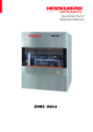
Download DWL 66FS - BYU Cleanroom
Transcript
UserGuide Part I
System Operation
DWL 66FS
HEIDELBERG INSTRUMENTS DWL 66FS User Guide Part I
TABLE OF CONTENTS
PREFACE...................................................................................................................................1
RELATED DOCUMENTATION ..................................................................................................2
CONVENTIONS USED ..............................................................................................................2
CONTACT ..................................................................................................................................3
CHAPTER 1 - GETTING STARTED ..........................................................................................4
Introduction.............................................................................................................................4
SAFETY PRECAUTIONS...........................................................................................................5
Warnings ................................................................................................................................5
General Precautions...............................................................................................................5
Laser Safety ...........................................................................................................................6
Electrical Safety......................................................................................................................6
SYSTEM COMPONENTS ..........................................................................................................7
Granite System.......................................................................................................................7
Flowbox ..................................................................................................................................9
Optics System ......................................................................................................................10
Electronic Control Units ........................................................................................................14
User PC................................................................................................................................15
Conversion Station ...............................................................................................................17
APPLYING POWER / POWERING DOWN .............................................................................18
Applying Power Instruction: ..................................................................................................18
Powering Down Instruction:..................................................................................................20
CHAPTER 2 - HOW TO PREPARE TASKS ............................................................................21
Introduction...........................................................................................................................21
CHANGING WRITE HEAD AND EXPOSURE MODE .............................................................22
Introduction...........................................................................................................................22
Changing Writehead Instruction...........................................................................................22
Changing System Configuration Instruction .........................................................................23
CHECK INTERFEROMETER STATUS ...................................................................................24
LOADING..................................................................................................................................25
FOCUSING...............................................................................................................................28
GLOBAL ANGULAR ALIGNMENT ...........................................................................................29
Introduction...........................................................................................................................29
Manual Align Procedure .......................................................................................................29
SETTING THE ORIGIN ............................................................................................................31
Introduction...........................................................................................................................31
Origin Instruction ..................................................................................................................31
ii
HEIDELBERG INSTRUMENTS DWL 66FS User Guide Part I
PREPARING FIELD ALIGNMENT SEQUENCES....................................................................32
Introduction...........................................................................................................................32
Setup of a Field Alignment Procedure..................................................................................33
CHAPTER 3 - HOW TO DO EXPOSURES .............................................................................36
Introduction...........................................................................................................................36
CREATING A JOB ENVIRONMENT ........................................................................................37
Adjusting the Exposure Map ................................................................................................37
JOB SETUP..............................................................................................................................40
Introduction...........................................................................................................................40
Job Setup Instructions..........................................................................................................40
EXPOSING ...............................................................................................................................46
Introduction...........................................................................................................................46
Expose Instruction................................................................................................................47
Options .................................................................................................................................49
OVERLAY EXPOSURES .........................................................................................................50
Introduction...........................................................................................................................50
Testing and Adjusting Overlay Accuracy..............................................................................50
Overlay Exposure Instruction ...............................................................................................52
USING BACKSIDE ALIGNMENT .............................................................................................53
Introduction...........................................................................................................................53
Testing and Adjusting BSA Accuracy...................................................................................53
CHAPTER 3 - HOW TO DO METROLOGY ............................................................................54
Introduction...........................................................................................................................54
OVERLAY MEASUREMENTS .................................................................................................55
Introduction...........................................................................................................................55
Large Box in Box Method .....................................................................................................56
Small Box in Box Method .....................................................................................................57
Overlay Measurements Instruction.......................................................................................57
DISTANCE MEASUREMENTS ................................................................................................60
Introduction...........................................................................................................................60
Measurements Using Manual Alignment Instruction............................................................61
Measurements Using a Template Instruction.......................................................................62
POSITION MEASUREMENTS .................................................................................................63
Introduction...........................................................................................................................63
Position Measurements Instruction ......................................................................................63
LINEWIDTH MEASUREMENTS ..............................................................................................66
Introduction...........................................................................................................................66
Model....................................................................................................................................67
iii
HEIDELBERG INSTRUMENTS DWL 66FS User Guide Part I
Properties .............................................................................................................................67
Linewidth Measurement Instruction......................................................................................68
PITCH AND STITCHING..........................................................................................................71
Introduction...........................................................................................................................71
Models ..................................................................................................................................71
Pitch Measurements Instruction ...........................................................................................72
CAMERA CALIBRATION .........................................................................................................75
Camera Calibration Instruction.............................................................................................75
CHAPTER 4 - ERRORS AND TROUBLESHOOTING ............................................................77
CHAPTER 5 - OPERATOR MAINTENANCE ..........................................................................79
Introduction...........................................................................................................................79
System Checks ....................................................................................................................79
Environmental Adjustments..................................................................................................79
Doc. No.: DWL-HI-022
Revision: 1 (Juli 2007)
Copyright © 2007 by Heidelberg Instruments
iv
HEIDELBERG INSTRUMENTS DWL 66FS User Guide Part I
Preface
This manual is meant to help the user to start working with the main applications of the
DWL66FS laser lithography system. It contains a brief system description and step-bystep instructions for the standard tasks of the system operator.
This preface gives information about the terminology used in this manual as well as
additional sources of information and support.
In the first chapter, a brief overview of the system components and their interaction is
given.
The second chapter contains simple step-by-step instructions for exposure jobs. They
guide the operator through preparation and completion of exposure jobs using the
DWL66FS menu, the graphical user interface designed to give the operator an easy-touse control over the system functions.
In chapter three, the measurement features of the DWL66 are being explained. This set
of functions is dedicated to position and linewidth measurements for system calibration
or quality checks.
Chapter four gives some simple troubleshooting procedures for common problems.
The last chapter contains information on maintenance procedures.
1
HEIDELBERG INSTRUMENTS DWL 66FS User Guide Part I
Related Documentation
Heidelberg Instruments offers several further Manuals related to the machine and its
operation. If you did not get one of these or need an update, please contact Heidelberg
Instruments, Germany.
Preinstallation Guide
System requirements, sizes and weights of
components etc.
Conversion Software Manual
Manual for the HIMT conversion software
used for data preparation and fractioning
User Guide, Part II
Reference Manual for functions of the GUI as
well as the Matrix Commander program
Conventions used
Throughout this manual there are safety warnings. To classify the degree of danger in
each of these situations, the following notation is used:
CAUTION:
Advises that you risk damaging your equipment if you do not heed
instructions.
WARNING: Advises that you risk danger to personal health if you do not follow
instructions carefully.
2
HEIDELBERG INSTRUMENTS DWL 66FS User Guide Part I
Contact
Should you need assistance, please call Heidelberg Instruments during normal
business hours (CET)
Phone:
Fax:
+49-6221-3430-0
+49-6221-3430-30
or contact your local service office:
China:
Japan:
Heidelberg Instruments China
Rm.101, Block 1, Animation Park,
Yuehai Street, Nanhai Road,
Nanshan Distr., Shenzhen 518045
China
Phone: +86-755-8301599-1 / -2 / -7
Fax:
+86-755-8301599-4
Heidelberg Instruments Japan
Germany Center for Industry & Trade
1-18-2, Hakusan
Midori-ku, Yokohama, 226-0006
Japan
Phone +81-45-938-5250
Fax +81-45-938-5251
Taiwan:
USA:
Heidelberg Instruments Taiwan
5F,No. 174 Chung Yang Road,
Hsinchu City
Taiwan
Phone: +886-35311-304/-284
Fax:
+886-35311-243
Heidelberg Instruments Inc. USA
2807 Oregon Court, Unit E2
Torrance, CA, 90503
USA
Phone: +1-310-212-5071
Fax:
+1-310-212-5254
Korea:
Heidelberg Instruments Korea
#316 Expo Officetel, 381
Mannyeon-dong, Seo-gu
Deajeon 302-834
South Korea
Phone: +82-42-482-1668
Fax:
+82-42-482-1669
You can also reach Heidelberg Instruments via e-mail: [email protected], or visit our site on
the Internet: http://www.himt.de
3
HEIDELBERG INSTRUMENTS DWL 66FS User Guide Part I
CHAPTER 1 - GETTING STARTED
HEIDELBERG INSTRUMENTS
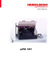
DWL 66 fs
DWL 66 SYSTEM FRAME
ELECTRONICS
USER PC
INTRODUCTION
The DWL 66FS is a high-resolution imaging system where over a million dpi is achieved
using a 25-nanometer writeable address grid for exposing metallized plates or wafers.
Depending on the individual X/Y stage, a DWL 66 fs will accommodate media up to 6 x
6 inches or even 8 x 8 inches. Design data can be created with any program using
DXF, HPGL, Gerber, GDSII, or CIF format and is converted into a LIC format on a
“CONVERT“ workstation. Design data transfer to the system is then realized via an FTP
connection.
4
HEIDELBERG INSTRUMENTS DWL 66FS User Guide Part I
Safety Precautions
WARNINGS
•
The DWL machines use lasers and high voltage electronics.
•
Please read this section carefully before operating the system!
•
If instructions are not followed carefully, danger to personal health and damaging
the equipment is at risk.
GENERAL PRECAUTIONS
The DWL 66 fs protects operators from exposure to moving parts and laser energy
while operating the equipment. All moving parts, lasers and their associated optics are
enclosed within the laminar flowbox. During operation, opening the flowbox window will
automatically stop an exposure. Please observe the following safety precautions while
operating the DWL 66 fs:
•
Follow all warnings and instructions given in this manual, the user menu software, or
our engineers.
•
Ensure that both the voltage and frequency of a power source match the voltage
and frequency stated on the equipment’s electrical label.
•
Except when loading media, never push objects of any kind through openings in the
equipment. Dangerous voltage levels may be present. Conductive foreign objects
could produce a short circuit resulting in a fire, electric shock, or permanent damage
to your equipment.
•
To reduce the risk of electrical shock, always plug the DWL 66 fs into an approved
outlet with correct safe ground.
Power requirements are described in the
“DWL 66 fs Preinstallation Guide".
•
Not all power cords have the same current ratings. Household extension cords do
not have overload protection and are not meant for use with computer systems.
Never use household extension cords with the DWL 66 fs or any of its external
components.
5
HEIDELBERG INSTRUMENTS DWL 66FS User Guide Part I
LASER SAFETY
During normal operation, the DWL 66 fs is a class 2 laser product. Opening the optics
covers and leaving them open during exposures changes the laser class to that of the
exposure laser (3B or 4, depending on system configuration). In case of the optics
cover covering the laser, the safety class of the laser source directly applies upon
removal of the cover.
Only trained personnel may be allowed to remove any optics covers.
ELECTRICAL SAFETY
Operating power for the DWL 66 fs is supplied by a CEE type 220-240 V, 16 A
connector. Alternatively, a CEE type 220-240 V, 16 A single-phase female cable
connector can be used to connect a local-type cable to a local-type wall connector. See
the Preinstallation Guide for more details.
The following safety precautions should be observed when doors and covers are
opened and the equipment is energized.
•
Observe similiar electrical precautions as would be for any system consisting of 220240 VAC dedicated circuit single-phase power, and DC power supplies.
•
If access to the interior power of the system or any component is necessary while
the system is in operation, exercise extreme caution. Only qualified service
personnel should have access.
6
HEIDELBERG INSTRUMENTS DWL 66FS User Guide Part I
System Components
The DWL66fs system consists of the following main sub units:
•
Granite System
•
Flowbox
•
Optics System
•
Electronic Control Units
•
User PC
•
Data processing conversion workstation
GRANITE SYSTEM
The DWL main system consists of a heavy granite construction. Granite has been
selected for its weight and stability. These properties ensure
a) effective vibration isolation in connection with the air buffer system, and
b) a low expansion coefficient.
In order to maintain an even expansion coefficient, all other stage parts are constructed
from granite as well. Although this material has certain advantages granite is not
completely insensitive to external influences. Temperature and humidity play an
important role in the stability of the machine, therefore its external environment must be
kept extremely stable. The large volume of the granite results in a long adaptation
period before the machine can be expected to produce consistent results. Hence,
installation must be done in two stages:
STEP 1: System set up and function tests
These tests can be started when the granite system has been placed in its
final location for anywhere between 24 - 48 hours. They serve to demonstrate
the functionality of all components
•
Until a system has completely adapted to its location, final calibration
procedures will not prove useful
STEP 2: Calibration and end test
Once the system has thermalized and everything is functional, tests and
measurements for fine adjustment and end calibration are done. This
procedure is often followed by a final acceptance test in cooperation with the
customer.
7
HEIDELBERG INSTRUMENTS DWL 66FS User Guide Part I
ELEMENTS OF THE GRANITE CONSTRUCTION
SYSTEM SUPPORT:
The granite base is supported by a heavy-duty aluminum construction and four air filled
buffers for vibration isolation. These buffers are arranged in a quasi-three point system
as to avoid any unnecessary bending forces in the granite.
MAIN BLOCK:
The main granite block has gaps to
accept the air buffers so that the
block's center of gravity lies below the
attachment points of the air buffers.
This increases the stability of a system
during writing. The block also contains
screw
holes
to
attach
other
components to the granite system.
STAGE SYSTEM:
The stage system is a linear
Chosen for its reliability and
system's motion is controlled
Y-interferometer system and
controller.
motor X/Y-stage.
ease of use, the
using the X- and
the linear motor
The stage is equipped with a vacuum chuck.
OPTICS PLANE:
The optics plane contains all beam control elements, lenses and mirrors. The write
lens is also mounted on the optics plane and is directed downwards onto the substrate.
To minimize heat generation in this area, HeCd lasers are mounted above the optics
plane in an own compartment.
8
HEIDELBERG INSTRUMENTS DWL 66FS User Guide Part I
FLOWBOX
The flowbox provides a stable environment for the DWL in terms of temperature,
laminar airflow and clean air, guaranteeing controlled and constant exposure conditions
and thus minimal variation of exposure parameters.
The front of the flowbox features buttons for powering up or down the system, an
emergency STOP button, and a switch for lifting and lowering the window. The covers
of the flowbox can be removed for service by authorized service personnel.
WARNING: Opening the flowbox covers gives access to dangerous laser radiation.
ELEMENTS OF THE FLOWBOX
•
Window:
Used for loading and unloading the DWL; must not be opened during operation
(opening window will stop any movement and close laser shutter).
The toggle switch on the front of the flowbox controls the pneumatic system that lifts
and lowers the window.
•
Heating and Airflow System:
Airflow is adjustable to between 0.3 and 0.5m/s and is preset during adjustment for
optimum stability. The heating system is situated below the top of the flowbox, and is
regulated automatically by a temperature control unit. The temperature setpoint for the
flowbox should be chosen 2-3°C above the room temperature to allow stable control.
As an option, the air at the inlet can be precooled with an additional precooling chiller to
allow a temperature setpoint that is close to the room temperature.
The temperature stability, assuming ±1°C (±1.8°F) outside the unit, is ±0.1°C (±0.2°F)
on the inside.
CAUTION: Although provided with a standard plug, the heater is not to be plugged into
a standard outlet, rather into the designated outlet at the temperature
controller. The heating is installed by service personnel and is not to be
modified by the user. Improper installation can cause the system to
overheat and to be damaged beyond repair.
•
Light:
Depending on the type of coating on the plates to be exposed, a red or yellow light may
be switched on inside the flowbox.
9
HEIDELBERG INSTRUMENTS DWL 66FS User Guide Part I
OPTICS SYSTEM
The exposure optics of the DWL66FS consists of four major parts: The laser, the beamshaping modulator, the fast deflector and the write lens. Additional optics include the
camera systems for inspection, measurements and alignment, as well as the
interferometric system for stage position control.
CAUTION
All systems are factory adjusted and can only be worked on in the field by experienced
Service Engineers.
•
LASER UNIT:
The DWL 66 fs runs either a 442 nm HeCd laser or a 405-410 nm Diode laser. The
laser head is mounted directly above (HeCd) or on (diode) the granite base. The power
supply is in both cases set outside the system, as it generates heat.
WARNING
•
The laser is a class III b category, and under these conditions, personnel must
observe safety precautions (i.e., sufficient eye protection)
•
Never look directly into the laser beam
•
Never sight down a beam into its source
•
BEAM SHAPING MODULATOR:
An extremely swift modulator system, generating up to 32 various beam positions, can
digitally turn each beam position on and off.
10
HEIDELBERG INSTRUMENTS DWL 66FS User Guide Part I
•
FAST SCAN DEFLECTOR:
The acousto-optic deflector device generates a swift laser scan with an approximate
sweep rate of 40 kHz. The scan angle is imaged into the back focal plane of the write
lens resulting in a telecentric scan arrangement, so that the laser beam is always
perpendicular to the substrate.
•
WRITE LENS SYSTEM:
Various write lenses can be utilized. The focal length of typical lenses is as follows:
2mm: Used for high-resolution metallized plates and wafers
4mm: Used for high-resolution metallized plates and wafers
10mm: Used for low-resolution metallized plates
20mm: Used for high-resolution emulsion plates and films
40mm: Used for low-resolution emulsion plates and films
The customer, when adapting a system to a unique application, can exchange any lens.
An air gauge auto focus system is used to correct for variations in the glass plate
thickness by moving the lens accordingly with a piezo.
CAUTION
•
Make sure that the nozzle of the air gauge autofocus system never touches the
substrate, or the stage!
•
When handling a dismounted write head, take care not to scratch or dent the nozzle!
11
HEIDELBERG INSTRUMENTS DWL 66FS User Guide Part I
•
CAMERA UNIT:
The camera unit optics comprises a micro camera, a macro camera, and a white light
illumination. Such a unit can be used to inspect and measure plates and films. For
multi-layer applications the cameras are also employed for alignment. The cameras
are connected to a video image processing system offering a number of metrology
functions (see chapter three).
•
BACKSIDE ALIGNMENT CAMERA UNIT:
One of the options for the DWL66FS is the capability for alignment to a structure on the
backside of a substrate. The backside alignment camera unit comprises the same
components as the standard camera unit, plus a focusing objective.
•
INTERFEROMETER:
Only industry standard interferometer systems with proven qualifications are being
utilized. A stage position measurement device provides the necessary information for
the online position error correction system. Only through this function will a machine be
able to achieve its required level of precision.
12
HEIDELBERG INSTRUMENTS DWL 66FS User Guide Part I
CAUTION
•
Never interrupt any of the interferometer laser beams, since this causes the loss of
position information and, during movement, will cause the stage to stop immediately
•
If beams were interrupted, the interferometer must be reinitialized before machine
operation may be resumed
•
Do not touch the mirror surfaces! Touching a mirror surface with bare hands will
damage it beyond repair!
13
HEIDELBERG INSTRUMENTS DWL 66FS User Guide Part I
ELECTRONIC CONTROL UNITS
The electronic control of the DWL 66 fs consists of five
main parts positioned in separate slots of the electronics
control rack:
1
1. System Control Rack:
The system control rack contains all control units for
data processing and positioning. Central units are:
2
MAIN PROCESSOR (BAB740) – A 68030 Motorola
processor running under a multitasking OS9
operating system controls the subprocessors for
stage positioning, pixel generation and image
alignment via a VME bus. The main CPU board also
contains the connection to the ethernet network.
3
EXPOSURE MEMORY UNIT (EMU) – A card
controlling 1 MB of 16-bit-SRAM modules for
processing exposure data
4
5
EXPOSURE CONTROL UNITS (ECU) – The ECUA2S unit gets exposure data from the EMU card and
controls functions like position-correction, intensityand frequency-correction, while the ECU-B counts X-/Y-positions and controls the
exposure timing.
DETC INTERFACE – A multi-channel ADC, DAC, and digital I/O board, used for
sensors, control signals and actuators, e.g. the auto-focus control, interferometer
initialization and the shutter.
IMAGE PROCESSOR – The imaging system consists of two cameras of different
resolutions, a frame grabber, an image processing board and a FIPS software
package. The BAB740 and its subsidiary board are controlling the latter parts.
2. Stepper Motor and AF Control Rack:
In this rack, all units controlling the motion of the system's stepper motors are to be
found. In addition, it contains the autofocus control board, which controls the
position of the write lens using a pressure sensor signal to correct the position of
the lens piezo actuators.
3. AO Rack:
This rack contains the electronics for control of the acousto-optic crystals. The HF
signal carrying the information for the laser beam positioning and intensity is
generated here as well as the frequency ramp for the scanning of the beam.
4. Power Unit
Main power unit including the emergency shutdown, relays and breakers
5. Anorad Controller Rack (behind panel):
This rack controls the stage motion by linear motors.
14
HEIDELBERG INSTRUMENTS DWL 66FS User Guide Part I
USER PC
The user PC runs the Windows User Menu, converting user input into DWL commands,
and thus controlling functions of the DWL 66 fs. The User PC is a tool for making the
DWL 66 fs easier to operate by minimizing handling errors.
The DWL 66 fs User Menu provides instant access to main functions via the control
toolbar:
Opens Control Panel for movement, focussing, camera settings etc.
Opens current Exposure Map
Starts a preprogrammed Manual Global Plate Alignment Sequence
Opens Mini-terminal window, for login and limited communication with the OS9system
Request Interferometer status
NOTE: The status shown in the label
button is pressed!
will only update when this
Resets Interferometer
NOTE: IF R also forces a stage reset!
Configuration file in use; double-click to change configuration (see
Chapter 2, Section Changing write head and Exposure Mode)
15
HEIDELBERG INSTRUMENTS DWL 66FS User Guide Part I
The main menu offers a number of logical menus:
•
File:
Contains the functions necessary to inspect which data files are available on the
machine's hard disk.
•
Job:
Exposure conditions and data sets of an Exposure Job are modified using the
commands in this menu. A prepared job may be opened for use or modification.
•
Setup:
The Setup commands allow for the setup or modification of a job environment as
well as the setup and testing of a number of automatic or semi-automatic sequences
for alignment, including the definition of image templates.
•
Measure:
Measure functions can be used for control of exposure quality.
•
Tools:
Offers access to a variety of tools for report analysis and other tasks.
•
Service:
Contains useful tools and functions for calibration and servicing, as well as the
function for changing the system configuration
•
Help:
Gives access to information about the software version, contacts, the software
history, and the index of help topics on the use of the menu software.
More information on the user menu will be given in the step-by-step instructions further
down in this manual. For a complete reference on all available menu functions, see the
User Guide II: Reference Manual.
16
HEIDELBERG INSTRUMENTS DWL 66FS User Guide Part I
CONVERSION STATION
CIF
GDSII
CONVERT
LIC
Gerber
DXF
The conversion workstation contains the conversion software package. The purpose of
this software is to convert source files from gerber, dxf, cif, gdsii, hpgl or structure
format into the LIC format the machine needs as input. During an exposure, this LIC
format data is converted in real time into the final pixel data set. Theoretically the
original design data could be converted directly to the final pixel set, but the advantage
of the LIC format is that its file size is much smaller due to a highly optimized
compression, leading to a much faster data transfer from the workstation to the system.
17
HEIDELBERG INSTRUMENTS DWL 66FS User Guide Part I
Applying Power / Powering Down
CAUTION
•
Never use a timer switch with the laser!
•
In case of emergency, press the large red STOP button located on the front of the
DWL machine.
APPLYING POWER INSTRUCTION:
1. Press the green ON-button located on the front panel of the DWL 66 fs.
•
If system was switched off with Emergency Stop button, that
button must be released first
•
If the power does not come up, check if the red main breaker at
the front of the electronics rack was switched off.
2. Switch on the User PC.
3. Open up the DWL66 user menu, by clicking on the
The following menu bar will appear:
4. Open up the Mini Terminal by clicking on the
appear:
MAIN BREAKER
icon.
icon. The following window will
18
HEIDELBERG INSTRUMENTS DWL 66FS User Guide Part I
5. Press Enter for the login prompt to appear. Login by entering "dwl". The password
is set to "dwl" by the factory, but it can be changed (consult Heidelberg
Instruments).
6. Close the terminal by again clicking on the
icon or the X in the upper right
corner of the mini terminal window. A window will open showing the system settings
of the current configuration. Confirm with OK.
Now the communication port is available to process commands, and exposures can be
prepared.
7. Switch on the laser with the key switch.
externally controllable laser (e.g. diode): Open menu Laser and choose On.
NOTES
•
The exposure laser and the interferometer laser must warm up before initializing the
machine and exposing. Switch on the laser and the DWL 66 fs electronics at least
30 minutes before exposure.
•
When the DWL is not performing tasks for a longer time, it is advisable to close the
Main Menu and shut down the computer.
•
Even if the PC was shut down, it stays logged in at the system controller. The login
procedure only has to be performed again if the system controller electronics was
switched off or rebooted (menu message "DWL does not respond").
19
HEIDELBERG INSTRUMENTS DWL 66FS User Guide Part I
POWERING DOWN INSTRUCTION:
1. Switch off the laser using the key switch.
externally controllable laser (e.g. diode): Open menu Laser and choose Off.
2. Exit DWL66 Menu by highlighting Exit under the File submenu.
•
Confirm menu shut down in dialog box
3. Shut down Windows by pressing Alt-F4 or choosing shutdown from the start menu.
4. Switch off computer and monitor (if not done automatically).
5. Press the red OFF-button located on the front panel of the DWL 66 fs.
6. For a complete shutdown, switch off the red main breaker at the front of the
electronics rack.
20
HEIDELBERG INSTRUMENTS DWL 66FS User Guide Part I
CHAPTER 2 - HOW TO PREPARE TASKS
WARNING:
•
Be sure to read all safety instructions outlined in the safety precautions section at
the beginning of this guide or within this section before operating the DWL 66 fs.
•
Always observe all warnings during use of this laser device.
INTRODUCTION
This chapter contains instructions for all procedures that are needed before an
exposure or measurement process. These are
•
System setup instructions (configuration settings, substrate loading etc.)
•
Data preparation (setup of a job environment and the related task sets)
•
Matching of coordinate systems (alignment, setting of origin)
21
HEIDELBERG INSTRUMENTS DWL 66FS User Guide Part I
Changing Write Head and Exposure Mode
INTRODUCTION
The DWL 66 fs is designed such that the user can easily change the write head in order
to change the resolution of an exposure or measurement. The resulting resolution
values depend on the detailed system configuration and can be found in the system
specification section of the quotation.
CHANGING WRITEHEAD INSTRUCTION
CAUTION
•
Move the writehead completely up before changing as to minimize the risk of
damaging the nozzle.
•
Take care not to touch the interferometer mirrors during the process of write head
changing. Touching the interferometer mirrors with bare hands will damage them
beyond repair.
1. Unplug the motor cable and piezo cable (as shown in the figure below):
2. Use a #3 Metric Allen wrench to loosen the four screws located on the top of the
write head.
Top view of the write head:
1
Compressed
air hoses
Motor cable
3
4
2
Piezo cable
Writehead
22
HEIDELBERG INSTRUMENTS DWL 66FS User Guide Part I
CAUTION
a. Hold write head with one hand.
b. Push write head up while loosening the screws.
c. Be careful that write head does not fall and damage the nozzle and / or the
chuck.
3. Let write head carefully down until it rests on the plastic holders, then pull it out.
Hold it fast so it doesn't fall and touch the chuck.
4. Place new write head into the holder with the piezo connector and motor cable
facing away from the machine.
•
Don’t let the nozzle touch the chuck
5. Push write head in as far as it will go.
6. Tighten screws X-wise, as indicated below, while pushing up on the write head.
•
Make sure write head is tightly mounted and in its
correct position.
CHANGING SYSTEM CONFIGURATION INSTRUCTION
1. Open the DWL 66 fs menu on the User PC and double-click on the configuration
information field on the right side of the menu bar.
•
A window with the available DWL 66 fs configuration files will appear:
2. Change configuration according to the installed write head (e.g., 10mm.cfg for
10mm write head).
23
HEIDELBERG INSTRUMENTS DWL 66FS User Guide Part I
3. If preparing for an exposure, highlight the desired setup (e.g. b/w or grayscale, if
available)
4. Press Load it! -button
•
The system will now reload the menu with the new configuration file, and load
the corresponding data sets on the system electronics.
Check Interferometer Status
Before the stage can be initialized, the interferometer status has to be checked by
clicking on "IF ?" in the Main Menu.
•
If the label "IF ???" changes to "IF: OK,”proceed to the next section
•
If "IF: FAIL" appears, then reset the Interferometer by clicking on "IF R"
Reasons why the label might still read "IF: FAIL" after a reset are:
•
The machine was just switched on (the interferometers need about 20 minutes to
reach a stable state)
•
The interferometer laserbeam is blocked. Check for obstacles in the optical path
NOTE:
The IF status label is only updated when the "IF ?" or "IF R" buttons are
clicked.
24
HEIDELBERG INSTRUMENTS DWL 66FS User Guide Part I
Loading
1. Open the Control Panel by clicking on the
toolbar icon, or by clicking on the
DWL Control Panel under Service in the Main Menu.
2. Click on the INIT button (
•
) to initialize the stage.
During the first initialization after system (re-)start, the stage will move slowly in
negative X-direction and then in negative Y-direction until it reaches the end
switches, from where it will move back to the center position. Any other time the
INIT button is pressed, the stage only moves to the center, and the coordinate
system is being reset by the software.
25
HEIDELBERG INSTRUMENTS DWL 66FS User Guide Part I
•
The orientation of the machine's coordinate system is shown in the following
picture:
–X
+Y
–Y
+X
3. Click on the (UN)LOAD icon (
•
)
The write lens will move up, and the stage will then move to the load position.
NOTE:
The LOAD button is also available in the Expose window, which is
opened by highlighting Run Job under Job in the Main Menu.
4. Before loading the DWL 66 fs (i.e., loading the plate onto the chuck), plug the
stopper pins into the chuckholes for easy plate alignment.
5. If an unexposed plate will be loaded, switch off the white-light and switch on the
safelight in the clean room before opening the plate container. Check the
manufacturers data sheet to find out which kind of safelight applies for the plate type
used. Usually, for resist coated metallized plates or wafers, yellow safe light is
necessary.
•
Leave white light off until the plate is developed
CAUTION
•
If computer monitors are positioned close to the DWL they may, after a while,
expose the plates.
•
Make sure that monitor brightness is set to a minimum.
Make sure that monitors are covered when plates are being handled in front of
them for a long period.
7. Make sure plate and chuck are clean and smooth.
6. Take the plate out of the box.
8. Make sure the resist-covered side of the plate is facing up.
26
HEIDELBERG INSTRUMENTS DWL 66FS User Guide Part I
9. Place the plate onto the chuck.
•
Keep the plate a little tilted until the stoppers are reached.
•
Let the plate down carefully.
•
The plate should be roughly centered on the chuck.
10. Switch on the vacuum with the switch at the front of the chuck.
•
The four white screws at the front of the chuck are used to adjust the size of the
stage vacuum area to the plate size. All vacuum areas are arranged around the
center of the chuck.
→
4 cm x 4 cm vacuum area
→
6 cm x 6 cm vacuum area
→ 10 cm x 10 cm vacuum area
→ 12 cm x 12 cm vacuum area
→ 16 cm x 16 cm vacuum area
NOTE:
In case the plate is even smaller than the smallest vacuum area, use a
thick foil (e.g., copy foil) to cover the open chuckholes.
11. Once the plate is in place and the vacuum is switched on, make sure that the
vacuum hold down system is working properly by pushing the plate sideways.
•
If the plate can be moved, there is an air leak and suction must be improved by
pressing the plate down carefully onto the chuck.
CAUTION:
Do not touch the resist on areas to be exposed!
12. If, after pressing down on the plate it is still not held down tightly, check the surfaces
again for dirt or scratches.
•
If necessary, try a new plate.
27
HEIDELBERG INSTRUMENTS DWL 66FS User Guide Part I
Focusing
1. Open the Control Panel either by clicking on the
toolbar icon, by typing the "F9"
function key, or by choosing on DWL Control Panel under Service in the Main
Menu.
2. Click on the INIT button (
). The system will center the stage.
•
If the plate was placed in the center of the stage during loading, it is now
centered below the write head as well.
•
If not, you should move the center of the plate manually below the write head
using the XY STAGE control buttons.
3. Click on the FOCUS button (
).
CAUTION:
Before clicking on the FOCUS button, always make sure the
substrate is under the writehead. If the system focuses on anything else
but the substrate, the nozzle is liable to crash!
NOTE:
The FOCUS button is also available in the Expose window, which is
opened by highlighting Run Job under Job in the Main Menu.
NOTE:
The DeFoc-slider sets a focus offset leading to a different final position of
the lens with respect to the substrate. Usually it can be left in the default
position of 2048. The defocus value for the final exposure must be found
in a series of test exposures.
28
HEIDELBERG INSTRUMENTS DWL 66FS User Guide Part I
Global Angular Alignment
INTRODUCTION
Even when alignment stops are used, a substrate will usually not be loaded perfectly
parallel to the system's coordinate axes. However, in some applications, a correct
angular placement of the design is mandatory, and it is especially important for correct
measurement results. To align the coordinate system of the DWL to the angular
position of the substrate, it is therefore possible to manually do a global angular
alignment after loading. As alignment marks, preexposed structures can be used, or the
edges of the substrate. For an alignment along the x-axis, horizontal lines are best,
while for the y-axis, vertical lines are recommended.
CAUTION: If plate edges are used for alignment, no focussing may be done during the
routine, or a nozzle crash will occur!
MANUAL ALIGN PROCEDURE
1. Open the Control Panel by clicking on the
icon in the toolbar.
2. Select the camera that should be used for alignment. Use macro camera for rough
adjustment, micro camera for fine adjustment. In case of systems equipped with
backside alignment capability, FS stands for the front side camera system, BS for
the backside system.
3. Close the Control Panel by clicking on Exit.
4. Click on the Manual Global Alignment button
in the toolbar.
5. Systems with backside alignment only: If the alignment should be performed using
structures on the back side, click on the BS check checkbox. If the box is
unchecked, alignment will be performed using the top side.
6. Choose whether alignment is to be performed along the X- or along the Y-axis.
7. Point camera cursor to the first alignment site on the substrate using the manual
alignment window and click OK. If the site is not on the screen, click on Panel and
use the Control Panel functions to move the structure into the camera field using
the XY STAGE directional buttons. For reference on other control panel functions
that can be used for stage movement, see User Guide II.
8. Point camera cursor to the second alignment site on the substrate along the axis
chosen for alignment and click OK. If the site is not on the screen, click on Panel
and use the Control Panel to move the structure into the camera field.
29
HEIDELBERG INSTRUMENTS DWL 66FS User Guide Part I
9. The system will calculate the angle of rotation between the two points.
•
The rotation will be compensated by a computational rotation of the stage
coordinate system.
•
After calculation of the rotation, a dialogue box will appear showing the
calculated rotational angle and ask if the compensation should be executed.
10. Repeat Steps 2 – 4 until the measured angle is satisfactory.
•
Accept the last compensation, then click “Cancel” in the Point to 1st Site window
to complete the alignment sequence
NOTE
If tighter precision during a sequence is necessary, simply switch to the micro camera
using the Panel and use larger distances between the alignment sites. It should be
possible to align a substrate in accordance to the coordinate system within a few micro
radians, depending on the quality of the alignment sites and the resolution of the write
lens.
11. Click on "Set 0,0 …" to set the origin according to next instruction, or click on Exit to
close the Manual Global Alignment window.
30
HEIDELBERG INSTRUMENTS DWL 66FS User Guide Part I
Setting the Origin
INTRODUCTION
For a successful exposure it is extremely important to have the origin of the coordinate
system set to the correct location as required by the design (i.e., center of the plate,
lower left corner of the plate, etc.).
ORIGIN INSTRUCTION
There are two ways to set the origin. The version using the Control Panel is
comparatively coarse. If a structure exists that can be used to define the center with
higher precision, the Set 0,0 … sequence of the Manual Global Alignment window
should be used.
1. Determine the position on the plate, which the design requires as the coordinate
origin.
2. Manual Global Alignment: Click on Set 0,0 …. The Point to Set-to-Zero window
will appear.
3. If the write head is not already above the desired origin position, use the Control
Panel to move it there. To open it, click on the toolbar
icon or, in case of use of
the Manual Global Alignment, by clicking on Panel in the Point to Set-to-Zero
window.
4. Move the stage with the XY STAGE directional buttons, so that the nozzle gets
above the desired coordinate origin.
5. a) Control Panel version: When nozzle is in its correct position, click on the Set 0,0
button in the Control Panel.
•
The present position is defined as the origin of the coordinate system.
b) Manual Global Alignment version: Close the Panel. A crosshair will appear in
the monitor. Move the crosshair to the structure that defines the origin and click on
OK.
•
The system calulates the offest of the structure position from the image center
and sets the current coordinates accordingly.
Note: The Expose window discussed in the following chapter offers additional features
for setting the origin.
31
HEIDELBERG INSTRUMENTS DWL 66FS User Guide Part I
Preparing Field Alignment Sequences
INTRODUCTION
For overlay exposures as well as for automatic measurements it is important to align
the machine coordinate system to alignment structures on the substrate. Aside from
the manual angular alignment described before, this also means that the coordinate
origin for each field should be adjusted according to the position of an alignment
structure, which is part of each of these fields. To do this, a field alignment method for
detection of the structure position must be set up, and the coordinates corresponding to
the structure position within the design coordinate system must be entered into the Map
file.
32
HEIDELBERG INSTRUMENTS DWL 66FS User Guide Part I
SETUP OF A FIELD ALIGNMENT PROCEDURE
There are two ways of setting up a field alignment procedure for a DWL 66 fs. If the
alignment structure is a cross, the procedure may be prepared automatically by using
one of the Simple Cross Alignment commands under Setup in the main menu while
the structure is in clear view of the camera. If the structure to be used for alignment is
not a cross, the complete procedure must be setup automatically.
SETUP OF A SIMPLE CROSS ALIGNMENT:
1. Load plate and focus.
2. Using the Xy-Stage buttons in the Control Panel, move substrate so that the cross
is well within the monitor image field (as close to the center as easily possible).
3. Optimize camera settings (lamp, offset, gain) for best contrast.
4. Highlight Simple Cross Alignment under Setup in the main menu.
There are two methods offered:
•
Using Find XY for a cross with a clear outline
•
Using Pos XY for a cross where the outline is blurred, e.g., by an additional
resist layer
5. Indicate the borders of the cross following the instructions given.
•
The system will try to detect the cross and determine the width of the lines
•
All values (camera settings, alignment method settings) are entered into field
alignment procedure macro, which is automatically setup after the method has
been chosen and the cross has been detected
6. To check, test and edit the field alignment macro that has been created, highlight
Field Alignment Method. Check if the values obtained from the bracket behind the
alignment method are non-zero; otherwise, manually enter estimation for the values
necessary. All values are in tics.
•
Pos XY: Values to be entered are (in the following order)
–
Small side of measurement box: should be larger than the cross linewidth
–
Large side of of measurement box: 4 – 5 times the cross linewidth
33
HEIDELBERG INSTRUMENTS DWL 66FS User Guide Part I
–
Distance of measurement boxes from monitor image center: should be
around 200 pixels, depending on the size of the cross (more than one
linewidth)
7. Test method by clicking on Test button.
SETUP OF OTHER ALIGNMENT PROCEDURES
1. Load plate and focus.
2. Using the Xy-Stage buttons in the Control Panel, move substrate so that the
structure is well within the monitor image field
3. Optimize camera settings (lamp, offset, gain) for best contrast.
4. Highlight Field Alignment Method under Setup in the main menu.
•
The following window will open:
5. Empty the list of all entries by pressing Cut repeatedly.
6. Transfer the current camera settings to the edit line by pressing Cam; press Enter
on the keyboard to transfer this line to the command macro list.
7. Press Next to continue with the next command line.
8. From the selection box (upper-right corner of the Field Alignment Macros window),
choose the command delay() and press Use.
•
Enter the number of seconds the system should wait after a movement before
the alignment sequence starts
34
HEIDELBERG INSTRUMENTS DWL 66FS User Guide Part I
•
Press Enter on the keyboard to transfer the command to the list
9. Proceed to the next line and choose an alignment function from the list.
•
Find XY, Pos XY: Detect a cross (see Simple Cross Alignment)
•
Find Manual: Structure must be marked manually by the operator
•
Find Template: Structure is detected by comparison with a predefined template
•
Find X, Find Y: Detect horizontal / vertical lines; if both are used successively
(with a possible movement in between), the position of the point where the lines
would cross is the result of the alignment procedure
10. Repeat the alignment function if a higher precision is necessary (3-repetitions
recommended)
11. Test sequence by pressing the Test button.
For more in-depth explanations of the alignment functions or template definition, see
User Guide PART II: Reference Manual.
NOTE
A field alignment sequence should be tested thoroughly in different portions of the plate
before it is used for overlay exposures or measurements. Besides testing the
alignment sequence from the Field Alignment Macros window, it is also possible to
start a full alignment test run for all fields where alignment has been set to “1”* in the
Job file by pressing the Test Align button in the Exposure window (see previous
section). Highlighting Analyse Report for Alignment Results under Tools in the main
menu will allow for the viewing of test results.
*(or the number of alignment sites given in the map)
35
HEIDELBERG INSTRUMENTS DWL 66FS User Guide Part I
CHAPTER 3 - HOW TO DO EXPOSURES
INTRODUCTION
For exposures and automatic measurement sequences, the DWL requires several job
dependent data files:
•
Map File (.map) - containing information on positioning
•
Job File (.dwl) - containing data in which map fields which tasks should be
performed, and under what conditions.
•
Field Alignment File (.fa) - containing a sequence for coordinate alignment to
existing structures
All files for one project, including report files, have to be located in the same directory.
This set of files defines a Job Environment.
Once such an environment has been completed, an exposure (or automatic
measurement) process can be easily and repeatedly done using the Run Job utility.
36
HEIDELBERG INSTRUMENTS DWL 66FS User Guide Part I
Creating a Job Environment
1. Highlight New under Setup in the Main Menu.
•
The New Exposure Map window will appear:
2. In the directory select box on the left, \VBMENU\WAFER should already be
selected. If not, open these folders before proceeding.
3. a) To create a new job environment directory, click on the Create Map button and
input a name consisting of not more than eight characters.
•
The eight-character name entered is used as project name for all
components of the environment
•
A project directory is created and the program copies three default root files
from \VBMENU\WINDWL\ into the new directory, giving them new names
consisting of the project name and the respective extension.
b) To load an existing map, click on the environment folder in the directory select
box, then double-click on the map file (<project name>.map) listed to the right.
4. Confirm in dialog box to change to the new project environment.
5. Press Set Environment.
6. Exit New Exposure Map window.
ADJUSTING THE EXPOSURE MAP
If an exisiting environment was loaded, the data from this environment is now ready for
use. If a new environment was created, the default map is loaded and can be adjusted.
1. Highlight Exposure Map located under Setup in the Main Menu. The Exposure
Map Design window will appear, showing the settings of the current Map:
37
HEIDELBERG INSTRUMENTS DWL 66FS User Guide Part I
2. Click on the New button to create a map file without any values.
3. During exposure, each design will be exposed such that its origin falls onto the
center of the map field, or die, it is exposed in. Enter numbers according to sizes
and desired positions of the design or designs that are to be exposed:
LINE 1:
Field Width =:
• Enter desired width in micrometers
• Value must be large enough for the design
• If width is too small, there will be overlapping
LINE 2:
Field Height =:
• Enter desired height in micrometers
• Value must be large enough for the design
• If the height is too small, there will be overlapping
LINE 3 / 4:
Alignment Site X / Y =:
• Distance of the alignment sites to the origin of the die
• Up to four alignment sites can be entered, separated by commas
38
HEIDELBERG INSTRUMENTS DWL 66FS User Guide Part I
LINE 5:
Fields per Row =:
• For each row of dies, enter the number of dies it should contain,
separated by a comma. As many rows will be created as there are
numbers in this entry.
• The number of rows and fields per row must fit on the substrate
LINE 6:
Fields Start at X =:
• Enter position in micrometers where each row is to begin in the X
direction with respect to the field furthest to the left.
LINE 7:
Field Zero =:
• Enter the number of the field corresponding to the substrate origin
NOTE:
The center of this field is the zero point for the exposure! This has to
match the coordinate origin set before with the Control Panel or by using
the Set 0,0 … function of the Manual Global Alignment.
NOTE
If just one design is to be exposed on a mask without any alignment features, the Map
might look like the following:
Field Width = 100000 (value is of no importance, but may not be 0 or void)
Field Height = 100000 (value is of no importance, but may not be 0 or void)
Alignment Site X =
Alignment Site Y =
Fields per Row = 1
Fields Start at X =
Field Zero = 1
4. Click on the Draw button. The Map corresponding to the latest entries will be
displayed in the Map window.
5. Close Exposure Map Design window with the Exit button.
39
HEIDELBERG INSTRUMENTS DWL 66FS User Guide Part I
Job Setup
INTRODUCTION
When choosing Make Job in the Job menu, the Edit Job spreadsheet opens. This
sheet allows the user to choose exposure or measurement parameters, such as the
exposed Design (allowing also the selection of a predefined measurement routine
instead), Defocus, and Energy.
JOB SETUP INSTRUCTIONS
1. Highlight Make Job located under Job in the Main Menu. The Edit Job spreadsheet
will appear:
The contents of this spreadsheet determine which data set will be written where
and under what conditions.
2. Together with the Edit Job spreadsheet, a graphical representation of the Map
currently loaded for an exposure / measurement is being displayed. See User
Guide II for more information on the functions of the Map window.
40
HEIDELBERG INSTRUMENTS DWL 66FS User Guide Part I
3. The following options are located under File in the Edit Job window:
•
Highlight New to open an empty spreadsheet. The number of rows in the sheet
corresponds to the current Map file.
•
Load a Job file from the \VBMENU\WAFER\ directory (if available). If the
corresponding Map file is not loaded, then only the number of fields that cover
the current Map file will be displayed.
NOTE
The corresponding alignment file will not necessarily be loaded. If an alignment
is necessary, check the current alignment procedure before executing the new
exposure Job.
•
Load a New Map from the \VBMENU\WAFER\ directory. A New Map with
default settings appears, and a new Job file with the name: "NONAME.DWL" is
created. The name of the new Map is used to create a new environment folder
that will contain all environment and job files connected with the new map.
Each option will also automatically lead to an update of the Map window.
The following steps describe the setup of a new sheet column by column. For a
thorough description of available options and the Edit Job menu commands see the
User Guide, PART II.
4. In the Edit Job window, the first column (Field Column) shows the row number
which is at the same time the number of the corresponding field. It can not be
edited. Whenever a row in the spreadsheet is highlighted, the field with the
corresponding field number in the Map window will turn blue.
FIELD COLUMN
Contains a field number, which refers directly to the field in the wafer Map, shown
concurrently with the Edit Job window. The field number usually coincides with the
number of the row it is in, but this is not essential. Fields will be exposed according to
their position on the sheet and not according to the field number. However, fields
cannot be moved using the menu (Use i.e., MS Excel for moving fields).
41
HEIDELBERG INSTRUMENTS DWL 66FS User Guide Part I
5. Click on the first row of the do column. Now you can enter a value for this field in the
edit line at the top of the spredsheet. The value entered here determines whether
the Map field corresponding to this row is to be written.
DO COLUMN
•
Enter -1 if the flag is true and the field is to be written.
•
Enter 0 or leave the field empty, if you want the field to be skipped.
6. Click on the first row of the Ali column. The value entered here determines the
number of sites at which the prepared field alignment method is used:
ALI COLUMN
Enter the value:
ALI=:
No Alignment
ALI=0:
No Alignment
ALI=1:
One Site Alignment
ALI=2:
Two-Site Alignment
ALI=3:
Three-Site Alignment
ALI=4:
Four-Site Alignment
Multi-site alignment can be used to increase alignment accuracy and control more
coordinate system parameters:
1 site:
control of field origin
2 or 3 sites:
correction of linear distortions in one axis / two axes
4 sites:
rotational correction (on top of global alignment)
7. Click on the first row of the Xoff column. This value, determines the X offset in
microns of the starting point of the exposure from the point that is determined from
the Map geometry
•
The value may be negative and can have a decimal point
8. Click on the first row of the Yoff column. This value, determines the Y offset in
microns of the starting point of the exposure from the point that is determined from
Map geometry
•
The value may be negative and can have a decimal point
42
HEIDELBERG INSTRUMENTS DWL 66FS User Guide Part I
9. Click on the first row of the Design column.
•
To do an exposure (see the Exposures box below), enter the name of the
directory where LIC data is stored.
•
To make a measurement, enter the name of a measurement procedure (see
Measurements box below) proceeded by an “M:”
DESIGN COLUMN
Enter the path and name of the LIC directory where graphics data is stored.
1. Exposures:
It is possible to expose more than one design, or even the same design several times,
by entering more design names separated by a semicolon.
2. Measurements:
The name of the measurement file must be entered proceeded by “M:” (e.g.,
M:test.msr). If several measurements are to be executed in the same field, a
semicolon must separate the file names.
10. Click on the first row of the Defoc column.
•
Enter a value between 0 and 4095 as a focus offset
•
A value of 2048 means no defocus
•
If the cell in the Defoc column is left empty, the defocus value of the previous
exposure is used
•
The 4095 steps equal an (uncalibrated) range of approximately ± 10µm, so one
unit equals approximately 5 nm
•
Before making a final exposure, a series of fields with the same pattern at
various defocus levels is exposed to find the best focus offset for the exposure
(Necessary for substrates with relatively thick resists)
•
When choosing the defoc values for such a series, keep in mind that the focus
depth of e.g. the 4mm write lens is 1.8µm and the autofocus is stable within a
range of 100nm
•
Since the 40mm write lens has a focus depth of 250µm, it is not necessary to
adjust the autofocus offset when working with this lens
43
HEIDELBERG INSTRUMENTS DWL 66FS User Guide Part I
11. Click on the first row of the Energy column.
•
Enter the number for an intensity correction file: the file 100 sets the energy to
100%; 90 sets the energy to 90%, etc
•
Not all values are available. Generally, the values from 10 to 100 in steps of 10
are prepared. To check which files are available; open the mini-terminal and
type, “chd sys” followed by, “dir.” The files corresponding to the numbers will
appear with a preceeding “FI_”. Before leaving the Mini-Terminal, retype “chd.”
•
Similarly to finding the best focus by varying the defocus, the Energy column is
used for finding the best energy by varying the energy across an array of fields
•
If less than 30% of the maximum energy is necessary, use the grey filters for a
basic adjustment
12. Click on the first row of the Command column.
•
Enter a number of commands to be executed before or after the exposure or
measurement. The available commands are listed in the selection box on the
right above the Job table
•
To select a command, highlight it in the list and click on the Use button (The
command will be automatically added to the current command sequence)
•
Enter the numeric or string value, if required.
•
All commands to be executed before an exposure or measurement must be
preceded by the keyword BEFORE:
•
Commands to be executed after the exposure / measurement are to be
preceded by the keyword AFTER:
•
BEFORE: / AFTER: These two words must only appear once, but each can be
followed by a number of commands (The commands must be separated by a
semicolon)
•
For a list of available commands, refer to User Guide, Part II
CAUTION
Use the BEFORE: / AFTER: option with care and test it thoroughly.
44
HEIDELBERG INSTRUMENTS DWL 66FS User Guide Part I
NOTE
•
For special service jobs, the Command column is used for placing OS9 commands
•
Enter a command preceeded by OS9:
•
If an OS9 command is not preceded by any of the two keywords BEFORE: or
AFTER: the command will always be executed before an exposure / measurement.
13. Repeat steps 4: through 11: proceeding to the next spreadsheet row for every cycle.
•
Repeat for the number of rows (i.e. fields) necessary.
14. To save a current job file under a new name, scroll down and highlight Save As…
under File in the Edit Job Main Menu, or save it under the original name (if
applicable) by highlighting Save under File in the Edit Job Main Menu.
15. Once the setup of an exposure is complete, close both the Map and the Edit Job
window, by scrolling down and highlighting Exit located under File in the Edit Job
window.
45
HEIDELBERG INSTRUMENTS DWL 66FS User Guide Part I
Exposing
INTRODUCTION
The expose window is kept as simple as possible and can be used to routinely run predefined jobs. It also contains additional access points for most of the controls used
during exposure preparation (loading, focussing, aligning …).
Before exposing, make sure the correct environment and the correct job are loaded.
Now, follow the logical sequence given in the Expose window.
46
HEIDELBERG INSTRUMENTS DWL 66FS User Guide Part I
EXPOSE INSTRUCTION
1. externally controlled laser: If laser was set to Disable before, open Laser menu
and choose Enable. If laser is off, choose On.
NOTE: Exposure lasers need a warmup-time to stabilize before exposures should
be started (e.g. ~3 min for TOPTICA diodes). Refer to laser manufacturers
guide for detailed information.
2. Open the Expose window by highlighting Run Job under Job in the Main Menu.
•
The following window will appear:
If the substrate was not yet loaded and focused:
3. Load substrate and focus:
a. Click on the Load button. The stage will initialize if necessary, and move to the
load position. A dialog box appears.
b. Manually load the substrate.
c. Click OK in the dialog box to let the stage move back below the write head.
d. Click on Focus.
• Make sure substrate is completely under the nozzle before clicking on the
Focus button
4. If the origin was not previously set, the Expose window offers several possibilities
for choosing and setting the origin.
47
HEIDELBERG INSTRUMENTS DWL 66FS User Guide Part I
•
If the origin should be set in the center of the substrate, the Find Center function
can be used to detect the substrate edges using the autofocus and deducing the
substrate center position from them
CAUTION: Be sure to focus near the plate center before starting the Find
Center procedure
•
If the center position should be set in the stage center, press Center Stage and
then Set X=0,Y=0
•
If coordinate angle and origin should be set according to alignment marks, press
Manual Align. The manual global alignment procedure previously described will
be started.
5. To check if the field alignment works correctly in all fields, the Test Align button can
be used. Alignment results will be written to a report file.
6. To start an exposure, press Expose. Alternatively, an automatic measurement
sequence can be started by clicking on Measure. All alignment results,
measurement results, exposure commands and error are written to a report file in
the job environment directory.
•
The Map window is continuously updated during an exposure
•
While a field is exposed the User PC waits and displays how many stripes remain to
be written for each field
•
In case of an emergency, pressing the BREAK button in the During Exposure
window will interrupt the current exposure
•
After Break is pressed, the current stripe will finish and all processes necessary for
completing an exposure will be stopped.
NOTE:
Do not press the Expose button until everything is setup correctly, i.e., the
Make Job file is correct, the write head is in correct position, etc.
NOTE:
Make sure system is focused!
7. Once exposure is finished, click Unload button
•
Write head will move up while the stage moves to the unload position
8. The Edit Report button allows for the (test) exposure report to be viewed and saved
under a different name.
Note: The menu always stores reports for the same job under the identical name. To
preserve a report for later use, it is important to rename it!
48
HEIDELBERG INSTRUMENTS DWL 66FS User Guide Part I
OPTIONS
AUTO UNLOAD:
If checked, the Unload function will be executed automatically after the exposure is
finished.
JOB LOG:
If checked, the name of the exposure / measurement job environment is entered into
a list, followed by the first design name or measurement file name encountered.
Next, both start time and date and stop time and date are listed, and this information
is entered into the file, "JOBLOG.TXT" -which can be found under
C:\VBMENU\WINDWL.
LASER OFF: (only available in systems with externally controllable laser)
This will lead to an automatical shutdown of the laser after an exposure is finished.
DEBUG:
If continuous problem occur with a specific job, the debug mode can be used to
obtain more detailed information about the system processes for analysis by HIMT
service engineers.
This option needs a lot of disk space and should only be used if absolutely
necessary!
49
HEIDELBERG INSTRUMENTS DWL 66FS User Guide Part I
Overlay Exposures
INTRODUCTION
Several preparations are necessary to do overlay exposures:
Before starting an exposure of the second (third...) layer, the machine coordinate
system must be aligned to the previous layer(s) on the substrate, and the position of the
write beam must be measured with respect to the center of the monitor image.
Note: It is important that for overlay exposures, all layers are converted with the same
stripe width that the calibration was done with. Otherwise, an offset in x
corresponding to half the difference of the stripe width from the calibration stripe
width has to be taken into account.
TESTING AND ADJUSTING OVERLAY ACCURACY
The testing and adjustment of overlay accuracy must be executed whenever a write
head has been changed or removed for any reason since the last overlay exposure.
Such a procedure serves to measure the write spot position with respect to the center
of the monitor image, which is the reference point for alignment.
1. Load a fresh substrate and set the zero point in the center (use Find Center
function).
2. Load the environment for overlay test exposures which was setup for the current
write head: C:\VBMENU\wafer\align_<focal length of write head>
•
In systems with only one write head, the environment is sometimes called “align”
3. Expose the first layer of the test design.
50
HEIDELBERG INSTRUMENTS DWL 66FS User Guide Part I
•
In the Job file, enter “0” in the Ali cell, and “OL <focal length of write head>
mmCM” in the Lic Buffer cell
•
Choose standard energy and defocus
•
Run the exposure
4. After developing, load substrate and move one of the corner crosses of the design
close to the center of the monitor image. Edit the current field alignment method by
highlighting Field Alignment Method under Setup in the main menu and test the
method by pressing Test.
•
If problems occur, try to adjust the method until it works reliably
5. Execute
a
manual
alignment
procedure along the y-axis (choose
No) using the two crosses at either
end of the overlay design.
•
Press the Auto button to use the
Field Alignment Method for
structure position detection when
the crosses are well within the
monitor image field
•
Do not Set 0,0 position
6. Open Expose window and press the
Find Center button to determine the
coordinate origin (should be roughly
in the center of the sloping cross
structure).
7. Expose the second layer:
•
Change Ali to 4 so alignment is
executed using all 4 corner
crosses
•
Change design name to “OL
<focal length of write head>
mmCU”
•
Expose
51
HEIDELBERG INSTRUMENTS DWL 66FS User Guide Part I
8. After developing, determine the registration
between the layers either by using an
overlay measurement on the box-in-box
structures, or by checking the overlap of the
line structures.
•
Enter the numbers gained from the
measurement
into
the
menu
configuration file by adding it to the
values given for XBEAM and YBEAM
9. Perform another test exposure repeating
steps 1 through 8.
•
Repeat until registration is satisfactory
Note: The overlay test design is prepared with
a different magnification for each write
head. The numbers given in the picture
of Layer CM – CU are valid for
magnification 1, which is used for 20mm
write head. For the other write heads,
the numbers are scaling with the focal
length.
OVERLAY EXPOSURE INSTRUCTION
1. If since the last overlay exposure the write head has been moved for any reason,
perform the overlay accuracy test first.
2. Expose and develop first layer.
3. Setup a field alignment method for a typical structure, which should be used for
alignment of the coordinate origin for each field.
4. Perform a manual alignment for rotational correction.
5. Set the origin in the position demanded by the design.
6. In the Map file, enter the positions of the field alignment sites relative to the
respective field origin (Parameters Alignment Site X= and Alignment Site Y=; up to
four sites with identical structures may be defined, coordinates are then set apart by
commas).
7. Open Exposure window and perform a Test Align procedure to verify that all sites
are found for all fields.
8. Start second layer exposure.
52
HEIDELBERG INSTRUMENTS DWL 66FS User Guide Part I
Using Backside Alignment
INTRODUCTION
If the system is equiped with the backside alignment option, exposures and
measurements can be done in a defined position with respect to reference marks on
the backside of the substrate, using the backside alignment cameras. All processes are
identical apart from that the backside check has to be activated, and the backside
camera system has to be calibrated.
TESTING AND ADJUSTING BSA ACCURACY
The testing and adjustment of overlay accuracy must be executed whenever a write
head has been changed or removed for any reason since the last BSA adjustment.
Such a procedure serves to measure the write spot position with respect to the center
of the backside monitor image, which is the reference point for backside alignment. An
overlay pattern of a frame centered around a square should be used for the test. As
the thickness of the substrate is of importance in this calibration, the procedure needs
to be performed independently for different types of substrates.
1. Expose reference marks on top of a photoresist coated substrate and etch this
pattern.
2. Coat the backside of the substrate with photoresist.
3. Flip substrate so that the reference marks are on the bottom side and the resist
coated side is on the top.
4. Align along y-axis with a BSA camera using the Manual Alignment function.
5. Set one of the alignment marks as reference point and expose the square.
6. Rotate substrate by 180 degree and align the y-axis again with the same backside
camera. Set the same alignment mark as reference point as before and expose the
frame.
7. Develop pattern.
8. Measure the misalignment of the overlay pattern. The calibration offset is half the
misalignment of each axis.
9. Enter the offsets gained from the measurement into the menu configuration file by
adding it to the values given for XBEAMBS and YBEAMBS, and repeat procedure
until a good match is reached.
53
HEIDELBERG INSTRUMENTS DWL 66FS User Guide Part I
CHAPTER 3 - HOW TO DO METROLOGY
INTRODUCTION
A number of measurement procedures to quantify exposures are listed under Measure
in the main menu. Some of these commands are specifically developed to aid with the
measurement of parameters important for system specific adjustments and calibrations.
Most metrology commands require top illumination, which will lower quality
measurement of emulsion plates if using the high magnification objectives with 4mm
and 10mm focal lengths.
•
Overlay:
Measures the relative positioning accuracy of two overlaid exposures on a single
plate by utilizing a number of models, such as box-in-box structures, etc.
•
Distance:
Offers both an automatic and a manual metrology method for measuring the
distances between two features on a substrate.
•
Positions:
Measures die-to-die alignment of a feature in order to ensure that the machine
coordinate system is linear and orthogonal.
•
Linewidth:
Measures and analyzes the line width of a feature based on its video profile.
•
Pitch, Stitching, Edge
Measures the distance between two identical features by associating video profiles
of the images and then searching for the maximum in the correlation function.
These measurements are then repeated in different locations and the results are
analyzed according to the method chosen.
54
HEIDELBERG INSTRUMENTS DWL 66FS User Guide Part I
Overlay Measurements
INTRODUCTION
The purpose of overlay measurements is to determine the registration between two
exposed layers that are printed on top of each other. In order to achieve the best
results, the micro-camera is used for most overlay measurements. The Heidelberg
Instruments PERFORM Test Pattern can be used to check the overlay quality of the
system. For each write head there are several special performance files available.
Measurement methods for two types of test patterns are availabe: The Large Box in
Box method, and the Small Box in Box method.
55
HEIDELBERG INSTRUMENTS DWL 66FS User Guide Part I
LARGE BOX IN BOX METHOD
REQUIRED PATTERN:
Part of the HIMT test pattern may be used:
A frame is written to a first layer
(e.g., "PFMXX_AX").
A second frame with equal line thickness but
of a different size is written onto the second
layer ("PFMXX_BX") over the first layer.
Ideally, the centers of the two squares
coincide.
How well the two layers actually do coincide, is
determined by the Overlay Measurements
program.
MEASUREMENT PROCEDURE:
Four fields must be defined as shown in the Large Box in Box figure above. Within
each of the four fields the pitch between the two lines is measured.
•
For the overlay measurement in the X direction the pitch measurements of the
fields 1 and 2 are compared
• For the Y direction the pitch measurement of the fields 3 and 4 are compared
The overlay error in x and y is then calculated from the difference between the X and Y
pitches, respectively.
•
The Large Box in Box structure is usually larger than the micro-camera field.
The system therefore must measure the fields sequentially and centers each one
on the screen before doing a pitch measurement
56
HEIDELBERG INSTRUMENTS DWL 66FS User Guide Part I
SMALL BOX IN BOX METHOD
REQUIRED PATTERN:
The Small Box in Box structure consists of
two patterns, as shown in the figure on the
right.
A frame is written to the first layer, and a
square is written to the second layer over
the first layer.
Ideally, the centers of the two structures
coincide.
How well the two layers actually do coincide,
is to be determined by the Overlay
Measurements program.
MEASUREMENT PROCEDURE:
The overlay is determined by measuring the distance between the symmetry axes, as
shown in the Small Box in Box figure above.
OVERLAY MEASUREMENTS INSTRUCTION
1. Load DWL with the substrate to be measured as described in the Loading and
Focusing sections.
2. Move stage to chosen overlay structure.
3. Highlight Overlay located under Measure in the Main Menu.
•
The following window will appear:
4. To proceed with a measurement file previously created in the \MEASURE directory,
open up the Overlay Measurements File menu, highlight Load and load desired
file.
•
The Model option is read from the file and switches on automatically
57
HEIDELBERG INSTRUMENTS DWL 66FS User Guide Part I
•
A Window will request to: “Point to the Reference Site,” relative to which all
positions will be measured
•
Once file is loaded, proceed directly to Step 11
5. To set up a new measurement file, choose one of the four models:
•
Large Box in Box-X:
Performs measurement previously described above in the X direction.
•
Large Box in Box-Y:
Performs measurement previously described above in the Y direction.
•
Box in Box-XY Model1:
(Actually: Small Box in Box Model) Performs measurement previously
described above, measuring x and y overlay quality at the same time.
•
Box in Box-XY Model2:
(Actually: Small Box in Box Model) Performs measurement previously
described above, and is especially designed for low contrast designs and
structures covered by a resist layer.
6. Click on the Set Up button, to setup measurement program.
7. Depending on which model was selected, the Define Box window appears,
requesting that measurement frames be placed over the structure.
8. After the measurement procedure is set up, click on Cancel to close the Define
Measurement #... window.
9. To save the measurement program, select a reference point.
58
HEIDELBERG INSTRUMENTS DWL 66FS User Guide Part I
•
If a reference point is not selected, the program will simply save the current
stage position as the reference point
•
To define a reference point click on the Relative To.. button
•
For a local series of measurements, the location of the first structure is usually
chosen as the reference point
When preparing a method for a fully automatic measurement procedure, the field
alignment site can be used
•
10. Save measurement program by highlighting Save Measurement located under the
File menu in the Overlay Measurements window.
•
In case a reference site has never been marked, a window will appear notifying
the fact and asking if the method should be saved anyway
11. Start measurement by clicking on the Measure button and continue the
measurement until enough data is collected.
•
A result window shows the updated values
•
After the measurement, the average value is displayed
12. To view measurement results click on the Results menu in the Overlay
Measurements window and highlight View and Save.
•
An editor displays the results, which may be saved by highlighting Save As..
under File in the Overlay Measurements window
13. Scroll down and highlight To Excel located under the Result menu in the Overlay
Measurements window to view results on a Microsoft Excel spreadsheet.
•
Highlighting To Excel will copy the results into the Clipboard
•
Start Microsoft Excel and load data into a spreadsheet by pressing CTRL-V or
by using the Paste function
•
All data processing options that Microsoft Excel offers are available
•
When spreadsheet results are complete return to the Overlay Measurements
window
14. Click Exit to return to the main menu window.
59
HEIDELBERG INSTRUMENTS DWL 66FS User Guide Part I
Distance Measurements
Distance = 203,342.03µ
Y
X
INTRODUCTION
The Distance Measurements program is designed for the measurement of distances
between structures on a substrate. A distance can be small as to fall within the camera
image, or large as to encompass the entire stage travel range.
Repeating
measurements several times can enhance the precision, and will result in additional
statistical information. The best values are obtained when automatic template
recognition is used for the real measurement.
60
HEIDELBERG INSTRUMENTS DWL 66FS User Guide Part I
MEASUREMENTS USING MANUAL ALIGNMENT INSTRUCTION
1. Load the DWL with the substrate to be measured as described in the Loading and
Focusing sections.
2. Use the XY STAGE directional buttons on the Control Panel for moving the stage
to the structures to be measured.
3. Open the Distance Measurements window by highlighting Distance located under
Measure in the Main Menu.
4. Check Manual inside the Alignment box.
•
For instructions on how to proceed using a template, read the next section
5. Click on the Set Up Measurement button and the Point to 1st Site window will
appear.
6. Using the cursor, select first and second measuring sites.
•
If the two sites do not fall within the camera field, use the Control Panel to move
the stage
•
The Control Panel may be used to switch between cameras, adjust the contrast,
etc
7. To view the two chosen reference sites, click on the Goto Site 1 and the Goto Site
2 buttons.
8. Set the Repeat Measurement # times box to at least 5 for a good measurement.
9. Start the measurement by clicking on the Repeat Measurement button.
• When measurement is complete, the distance between the two points will be
shown in microns
61
HEIDELBERG INSTRUMENTS DWL 66FS User Guide Part I
10. When distance measurements are complete, click Exit and return to the main menu
window.
MEASUREMENTS USING A TEMPLATE INSTRUCTION
1. Load the DWL with the substrate to be measured as described in the Loading and
Focusing sections.
2. Use the XY STAGE directional buttons on the Control Panel for moving the stage
to the structures to be measured.
3. Open the Distance Measurements window by highlighting Distance located under
Measure in the Main Menu.
4. Choose one of the templates offered in the Alignment field
•
If there are no templates, click on the Make Template button
•
For an explanation on how to define a template, refer to User Guide II
5. Once a template is defined, set the Repeat Measurement # times box to at least 5.
•
The higher the value, the more precise the measurement, and the lower the
value, the less time measurement takes
6. Start measurement by clicking on the Repeat Measurement button in the Distance
Measurements window.
•
When measurement is complete, the distance between the two points will be
shown in microns
7. When distance measurements are complete, click Exit and return to the main menu
window.
62
HEIDELBERG INSTRUMENTS DWL 66FS User Guide Part I
Position Measurements
INTRODUCTION
Position measurements provide information, not only about distances, but angular
distortions or non-linearity over a substrate as well. Position measurements are
therefore an important tool for initial system calibration and exposure quality control.
POSITION MEASUREMENTS INSTRUCTION
1. Load the DWL with the substrate to be measured as described in the Loading and
Focusing sections.
2. Using the XY STAGE directional buttons on the Control Panel, move the stage to
the structure to be measured.
3. Open the Position Measurements window by scrolling down and highlighting
Positions located under Measure in the Main Menu.
63
HEIDELBERG INSTRUMENTS DWL 66FS User Guide Part I
4. To proceed with a measurement file previously created in the \MEASURE directory,
open up the Position Measurements File menu, highlight Load and load desired
file.
•
The Model option is read from the file and switches on automatically
•
A Window will request to: “Point to the Reference Site,” relative to which all
positions will be measured
•
Once file is loaded, proceed directly to Step 10
•
To set up a new measurement file, choose one of the Methods described above
for a measurement in the X or in the Y direction
5. Click on the Set Up button, to setup measurement program.
6. Depending on which model was selected, the Define Box window appears,
requesting that measurement frames be placed over the structure.
7. After the program is set up, click on Cancel to close the Define Box window.
8. Start measurement by clicking on the Measure button and continue the
measurement until enough data is collected.
•
A result window shows the updated values
•
After the measurement, the average value is displayed
9. To save the measurement program, select a reference point.
•
•
If a reference point is not selected, the program will simply save the current
position as the reference point
To define a reference point click on the Relative To.. button
64
HEIDELBERG INSTRUMENTS DWL 66FS User Guide Part I
•
For a local series of measurements, the location of the first structure is usually
chosen as the reference point
•
When preparing a method including a fully automatic program, the field
alignment site can be used
10. Save measurement program by highlighting Save Measurement located under the
File menu in the Position Measurements window.
•
In case a reference site has never been marked, a window will appear notifying
the fact and asking if the method should be saved anyway
11. To view measurement results click on the Results menu in the Position
Measurements window and highlight View and Save.
•
An editor displays and will save the results
12. Scroll down and highlight To Excel located under the Result menu in the Position
Measurements window to view results on a Microsoft Excel spreadsheet.
•
Highlighting To Excel will copy the results into the Clipboard
•
Start Microsoft Excel and load data into a spreadsheet by pressing CTRL-V or
by using the Paste function
•
All data processing options that Microsoft Excel offers are available
•
When spreadsheet results are complete return to the Position Measurements
window
13. Click Exit to return to the main menu window.
65
HEIDELBERG INSTRUMENTS DWL 66FS User Guide Part I
Linewidth Measurements
INTRODUCTION
The line width measurement program allows line widths in the X and Y direction as well
as circle diameters to be measured. In order to achieve the most precise results,
modify Lamp, Gain and Offset parameters of the camera in the Control Panel to
optimize the contrast of the image.
As shown in the figure on the right, a box is to be defined
across the line. The pixels belonging to the line structure
are summed up vertically, which results in a curve with a
variation in X. A fit is performed on the curve and the
fitted curve is normalized.
In the Figure shown on the left, the line
width is determined by finding the
expansion in X of a fit to the measured
intensity values at a given threshold value.
The Figure shows that there are different methods for finding the expansion in X
(Inside, Outside, etc.), and various procedures and thresholds can be defined.
66
HEIDELBERG INSTRUMENTS DWL 66FS User Guide Part I
MODEL
•
LineWidth-X:
Measures the width of vertical lines.
•
LineWidth-Y:
Measures the width of horizontal lines.
•
Thick LineWidth-X:
Selects the measurement method for thick vertical lines (larger than ½ monitor
image).
•
Thick LineWidth-Y:
Selects the measurement method for thick horizontal lines (larger than ½ monitor
image).
PROPERTIES
•
Threshold=#:
Defined in percent, with the amplitude of the normalized video profile equal to 100%.
For most purposes the threshold value should range between 25% and 50%.
•
Repeats=#:
In order to improve the results, the pixel count for the whole box can be done
several times and the result will be averaged.
•
Inside:
The line width is defined as the horizontal expansion of the profile at the threshold
value. The profile is traced until the threshold height is reached, starting at the
center.
•
Outside:
•
The line width is defined as the horizontal expansion of the profile at the threshold
value. The profile is traced until the threshold height is reached, starting at the
endpoints.
Minimum:
67
HEIDELBERG INSTRUMENTS DWL 66FS User Guide Part I
The line width is defined as the distance between the two minima. The location of
the extrema is found by locally fitting a parabola.
NOTE
•
There are several ways to define the line width, meaning that obtained values are
only useful for comparing line widths.
•
The values are not correct on an absolute scale.
•
If the absolute values are necessary, an offset must be defined using a calibration
standard.
LINEWIDTH MEASUREMENT INSTRUCTION
1. Load the DWL with the substrate to be measured as described in the Loading and
Focusing sections.
2. Using the XY STAGE directional buttons on the Control Panel, move the stage to
the line or circle structure to be measured.
3. Open the Line Width Measurements window by scrolling down and highlighting
Linewidth located under Measure in the Main Menu.
4. To proceed with a measurement file previously created in the \MEASURE directory,
open up the Line Width Measurements File menu, highlight Load and load desired
file.
•
•
The Model option is read from the file and switches on automatically
A Window will request to: “Point to the Reference Site,” relative to which all
positions will be measured:
68
HEIDELBERG INSTRUMENTS DWL 66FS User Guide Part I
•
Once file is loaded, proceed directly to Step 12
5. To set up a new measurement file, choose one of the Methods described above.
6. Choose the Properties as described above.
7. Click on the Set Up button, to setup measurement program.
8. Depending on which model was selected, the Define Box window appears,
requesting that measurement frames be placed over the structure.
9. After the program is set up, click on Cancel to close the Define Box window.
10. To save the measurement program, select a reference point.
•
If a reference point is not selected, the program will simply save the current
position as the reference point
•
To define a reference point click on the Relative To.. button
•
For a local series of measurements, the location of the first structure is usually
chosen as the reference point
•
When preparing a method for a fully automatic measurement procedure, the field
alignment site can be used
11. Save measurement program by highlighting Save Measurement located under the
File menu in the Line Width Measurements window.
• In case a reference site has never been marked, a window will appear notifying
the fact and asking if the method should be saved anyway
12. Start measurement by clicking on the Measure button and continue the
measurement until enough data is collected.
•
A result window shows the updated values
69
HEIDELBERG INSTRUMENTS DWL 66FS User Guide Part I
•
After the measurement, the average value is displayed
13. To view measurement results click on the Results menu in the Line Width
Measurements window and highlight View and Save.
•
An editor displays the results, which may be saved
14. Scroll down and highlight To Excel located under the Result menu in the Line
Width Measurements window to view results on a Microsoft Excel spreadsheet.
•
Highlighting To Excel will copy the results into the Clipboard
•
Start Microsoft Excel and load data into a spreadsheet by pressing CTRL-V or
by using the Paste function
•
All data processing options that Microsoft Excel offers are available
•
When spreadsheet results
Measurements window
are
complete
return
to
the
Line
Width
15. Click Exit to return to the main menu window.
70
HEIDELBERG INSTRUMENTS DWL 66FS User Guide Part I
Pitch and Stitching
INTRODUCTION
In many cases it is important to measure the distance between two structures, located
relatively near to each other. If such structures are identical in appearance, the
distance being measured- or pitch is uniquely defined by a numerical comparison of the
two video profiles of each structure. A cross correlation will yield the pitch with an
extremely high repeatability.
MODELS
STITCHING MEASUREMENTS:
Determines the vertical distance of two horizontal lines or the horizontal distance of two
vertical lines and is designed to run DWL stitching performance measurements in both
X and in Y, using the system test pattern.
•
Stitching-X:
Measures the distance between two vertical lines, on both left and right sides of a
stripe border, and will repeat the measurement in other locations on the substrate, if
required. The RMS deviation of the results from the resulting average will determine
stitching quality in X.
•
Stitching-Y:
Measures the vertical distance between the sections of two horizontal lines, on both
left and right sides of a stripe border, and will repeat the measurement in other
locations on the substrate, if required. The RMS deviation of the results from the
resulting average will determine stitching quality in Y. This value depends on the
stage velocity and therefore must be minimized by optical adjustment for each
configuration individually.
PITCH MEASUREMENTS:
The pitch measuring method is applied for finding the horizontal distance of two vertical
lines or for finding the vertical distances of horizontal lines. This method may be
extended to measure whole sets of equidistant lines.
•
Pitch-X:
Compares the distance between two vertical lines or a row of equidistant lines over
a programmed area.
71
HEIDELBERG INSTRUMENTS DWL 66FS User Guide Part I
•
Pitch-Y:
Compares the distance between two horizontal lines or a row of equidistant lines
over a programmed area.
EDGE MEASUREMENTS:
The measurement of edge roughness in an exposure; the position of a horizontal or
vertical edge is measured at a number of positions along the edge.
The RMS
deviation of a fit through these position measurement results will determine edge
roughness.
•
Edge-X:
Determines the roughness of a vertical edge due to position fluctuations. No other
structures may be close to the edge.
•
Edge-Y:
Determines the roughness of a horizontal edge due to position fluctuations. No
other structures may be close to the edge.
OTHER APPLICATIONS:
• Scan Linearity:
If Scan Linearity is measured, a series of pitch measurements are applied to
successive positions in the linearity measurement area of the DWL
PERFORMANCE PATTERN. The RMS deviation of the average becomes the scan
linearity quality.
PITCH MEASUREMENTS INSTRUCTION
1. Load the DWL with the substrate to be measured as described in the Loading and
Focusing sections.
2. Using the XY STAGE directional buttons on the Control Panel, move the stage to
the first line to be measured.
3. Open the Pitch Measurements window by scrolling down and highlighting Pitch,
Stitching, Edge, Positions located under Measure in the Main Menu.
72
HEIDELBERG INSTRUMENTS DWL 66FS User Guide Part I
4. To proceed with a measurement file previously created in the \MEASURE directory,
open up the Pitch Measurements File menu, highlight Load and load desired file.
•
The Model option is read from the file and switches on automatically
•
A Window will request to: “Point to the Reference Site,” relative to which all
positions will be measured:
•
Once file is loaded, proceed directly to Step 11
5. To set up a new measurement file, choose one of the Methods described above for
a measurement in the X or in the Y direction
6. Click on the Set Up button, to setup measurement program.
7. Depending on which model was selected, the Define Box window appears,
requesting that measurement frames be placed over the structure(s)
8. After the program is set up, click on Cancel to close the Define Box window.
9. To save the measurement program, select a reference point.
•
If a reference point is not selected, the program will simply save the current
position as the reference point
73
HEIDELBERG INSTRUMENTS DWL 66FS User Guide Part I
•
To define a reference point click on the Relative To.. button
•
For a local series of measurements, the location of the first structure is usually
chosen as the reference point
•
When preparing a method including a fully automatic program, the field
alignment site can be used
10. Save measurement program by highlighting Save Measurement located under the
File menu in the Pitch Measurements window.
•
In case a reference site has never been marked, a window will appear notifying
the fact and asking if the method should be saved anyway
11. Start measurement by clicking on the Measure button and continue the
measurement until enough data is collected.
•
For Pitch Measurements, the first distance measured will be used as default, and
only the first box will have to be placed for every succeeding measurement
•
A result window shows the updated values
•
After the measurement, the average value is displayed
12. To view measurement results click on the Results menu in the Pitch
Measurements window and highlight View and Save.
• An editor displays the results, which may be saved
13. Scroll down and highlight To Excel located under the Result menu in the Pitch
Measurements window to view results on a Microsoft Excel spreadsheet.
• Highlighting To Excel will copy the results into the Clipboard
•
Start Microsoft Excel and load data into a spreadsheet by pressing CTRL-V or
by using the Paste function
•
All data processing options that Microsoft Excel offers are available
•
When spreadsheet results are complete return to the Pitch Measurements
window
14. Click Exit to return to the main menu window.
74
HEIDELBERG INSTRUMENTS DWL 66FS User Guide Part I
Camera Calibration
CAMERA CALIBRATION INSTRUCTION
1. Load substrate as described in Loading and Focusing.
2. Select camera to be calibrated and switch on the camera monitor
•
Use the DWL Control Panel to select camera
3. Move a clearly defined structure on the substrate (i.e., a cross) to the approximate
center of the screen.
4. Train system a template for finding the defined structure at various stage positions.
NOTE:
Camera calibration may also be done manually, but the result may be less
precise.
a) Use Gain and Offset slides to optimize contrast of the image.
b) Exit Control Panel.
c) Highlight Video Calibration under Service in the Main Menu and the Camera
Calibration window will appear.
75
HEIDELBERG INSTRUMENTS DWL 66FS User Guide Part I
d) Click on Make Template and the Define Template window will appear.
e) Define a template from the image on the monitor by placing a box of an
appropriate size above a structure or part of a structure, which can be easily
recognizable even if it is in a different part of the monitor image. First, place the
box and then choose the size.
f) Store the template in the temporary memory on the frame grabber-card by
clicking on Save Template in IPC.
g) Test template. If the result is poor, try to improve the contrast, or find a structure
better suited, and repeat instruction beginning at Step 4c).
5. Select number of data points and the range of the camera field over which the
calibration should take place.
•
Calibration range is limited to 90%, so the structure may drift out of view
6. Click on Calibrate button.
•
The stage will now be moved around the camera field and the position of the
plate is measured using the defined template
•
If manual mode is chosen, the operator must manually point to the structure’s
edge, or center at each measurement position
7. Click on Calculate and the system will calculate the best fit.
8. Replace old calibration value with the new one by clicking on Replace Current
Value.
9. Repeat full instruction for both axes and both cameras.
76
HEIDELBERG INSTRUMENTS DWL 66FS User Guide Part I
CHAPTER 4 - ERRORS AND
TROUBLESHOOTING
Most problems that can occur result in an error message by the menu suggesting
corrective action. This section lists some additional common difficulties and offers
possible explanations and solutions.
THE DWL WILL NOT IMAGE
1. Verify that the AC power cord is plugged into the wall outlet and that the outlet is
receiving power.
2. Verify that the flowbox window is completely closed.
3. Try rebooting the OS9 system and the user PC.
LINES NOT TO SIZE
Line thickness problems may have the following causes:
•
Developing technique (time, developer dilution etc.) not matched with material
requirements
•
Wrong resist thickness
•
Focus height incorrect
•
Incorrect exposure energy
•
Out of date material (fotosensitive coating, developer)
•
File creation error
FILM FOGGING
Fogging of emulsion coated films may have the following causes:
•
Too much ambient light
•
Safe light with wrong filter (Use a red filter or one recommended by the film
manufacturer)
•
Safe light on for too long
•
Out of date emulsion or media
•
Safe light power too high
77
HEIDELBERG INSTRUMENTS DWL 66FS User Guide Part I
•
Wrong developer
THE DWL STOPS ANYTIME DURING THE EXPOSURE
•
The accessed file is too big or the lic buffer is too small
- Try split lic
•
The DWL reached an endswitch, because the imaging area was set incorrectly
during conversion or in the menu map
•
The accessed file has the wrong format
•
The data file is too complex, which causes the MBCIII to be selected without being
READY.
– Try a slower writing speed or a smaller stripe width
•
The interferometer head is broken
PLATE COMES OUT COMPLETELY UNEXPOSED
•
Wrong substrate for this laser type
•
Something is blocking the beam path
ONLY HALF THE SCAN IS EXPOSED
•
Stripe distance was not entered correctly in the conversion (wrong writehead
chosen)
•
Wrong writehead installed
•
Wrong configuration was chosen
78
HEIDELBERG INSTRUMENTS DWL 66FS User Guide Part I
CHAPTER 5 - OPERATOR
MAINTENANCE
INTRODUCTION
The DWL 66 fs requires some minimal operator maintenance; however, only trained
service engineers should perform regular maintenance on the system. See Chapter 1 Safety Precautions.
SYSTEM CHECKS
Before operation the following routine maintenance should be performed:
1. Make sure all access covers are firmly in place.
2. Clean the chuck surface with a dry towel
3. Verify that the room temperature and humidity are within the following limits:
TEMPERATURE: 65° - 75°F (18° - 24°C)
NOTE
In addition to being within the recommended range, the temperature must be stable
(within 2°C) in order to assure high quality film and plate registration.
RELATIVE HUMIDITY: 40% to 60% (non-condensing)
CLEAN ROOM:
Class 1000
ENVIRONMENTAL ADJUSTMENTS
1. Allow room humidity to come within the specified range before using the MaskWrite.
2. If temperature is out of range, determine how long this condition has prevailed.
3. Adjust room temperature to within the specified temperature range and allow the
DWL to stabilize.
4. For stabilization of the system allow an amount of time equal to the time the
temperature was out of range.
NOTE
79
HEIDELBERG INSTRUMENTS DWL 66FS User Guide Part I
•
During imaging, the most accurate results are obtained when the environment
remains at a constant temperature and humidity.
•
If the system is equipped with a laminar flowbox, to achieve the optimum accuracy
during imaging, place substrate on chuck 2-3 hours before exposure, close DWL
window, and do not open window until exposure is finished.
80


