Download Standard Operating Procedure
Transcript
DWL-66 Laser Lithography
System Operating Procedure
Effective Date: 09/24/2012
Author(s): Jiong Hua
Phone: 402-472-3773
Email: [email protected]
1
1 Introduction
1.1 Key Words
Laser Lithography System, Optical Lithography, Pattern Transfer
1.2 Purpose
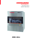
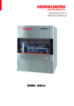
This document provides instructions for operating the DWL66 laser lithography tool, which is a
direct pattern generator by using laser beam exposure technique. It can work with most photo-resist
while mask is not required. Use of this tool requires the understanding of the fundamentals of optical
lithography and pattern design rules.
1.3 Applicability
1.3.1
Locations
The tool is located at Clean room of nanoscience research center.
1.3.2
Safety
The safety concern is the system uses high voltage electricity and the laser on this
machine is class 3B, meaning that it can cause serious injury to the eye if you stare
directly at the beam.
1.3.3
Restrictions and Limitations
•
Must be a qualified user of clean room and DWL-66 system.
•
The imitation for the sample is that it must not damage the system (between 1X1
inches to 5X5 inches).
1.4 Restrictions on Working Alone
•
Normal working hours are from 8am to 6pm M-F.
•
Working alone is permitted with completion of an orientation to this written procedure and
hands-on training from the specialist.
•
Assistance from the specialist is available during working hours only. If an error occurs
during off-hours, record the error in the Logfile and contact the specialist. Do not try to fix
or adjust anything by yourself. Tool will be checked in the following work day. User will
be notified when sample left in chamber is available for pickup.
•
Problems with equipment malfunctions, breakage, etc. should be reported to the specialist
and recorded in the tool Logfile. Again do not try to fix or adjust anything by yourself.
•
In case of any emergency, turn the main switch to “OFF”, leave the room and close the
door immediately. Contact the specialist right away.
•
For any emergency involving injuries, fire, chemical spills, etc., call 911.
2 Preparations
•
Receive this procedure from the specialist.
2
3 Execution (Step-by-step work breakdown)
Step #
1.
Alerts
Action
Transfer pattern file:
The user interface of the DWL66 system consists of two computers. Left
computer, called “Convert” below for convenience, is for pattern
conversion. Right computer, called “DWL” below for convenience, is for
system operation.
2.
•
In DWL computer (right computer), copy the pattern file from network
hard drive to the user folder of the local computer. Note: Ensure the
filenames have no hyphens or spaces in them.
•
In DWL computer, open up the data transfer software by double clicking
on the “Total Communication” icon on desktop. Press the corresponding
number according to the initializing window to start the program.
•
Start FTP link by clicking “Network” → “FTP”. In the pop-out window,
select “Convert” as remote computer. Wait until the communication
setup. In the program, there are two windows, the left one is Convert
computer and the right one is the DWL computer. Go the correct user
folder in both computers first. Transfer file can be done by dragging the
pattern files from right window to the left.
Logfile entries:
Open and fill out the log file with the corresponding parameters on the desktop
of the DWL computer.
3.
Opening Software:
•
In DWL computer (right computer), first start Mini Terminal by
double clicking the icon on desktop. A window will pop-out. Press
Enter once for the login prompt to appear. Login by user name: “dwl”
and password: “dwl”. Close the terminal by clicking the X in the upper
right and click “Yes” in pop-out window. (Now the communication
between computer and the system is set up.)
•
Open up the DWL66 user menu by double clicking on the
icon on
desktop. Wait until the menu bar appears. A window will open showing
the current setting of the system. Confirm with OK.
•
In the DWL66 menu, verify that the correct write head is loaded which
is shown on the right end of the menu bar. ( Normally it should be
10mm write head). If not, please contact specialist for help.
•
In the DWL66 menu, verify that the laser interferometer works in
normal condition, i.e.
shown in the menu bar. If not, click
button once to reset. Wait until
3
shows up.
•
In the DWL66 menu, switch on the diode laser (405 nm in wavelength)
in the main menu. It takes about 10 minutes
by clicking icon
before the laser beam stabilizes.
4.
Convert pattern file to Heidelberg format:
•
Login the Convert computer (user name: “convert” and password:
“convert”).
•
Start conversion job manager by clicking ONCE
desktop.
•
Create new job by clicking ONCE
icon in the menu. In the dialog
window, create a name for the job without hyphens or spaces. Click
“OK” to confirm.
•
Select the appropriate file type to add by clicking “Add”. The folder
containing those file types will automatically open. Select the file that
was previously copied to the computer. The system support different
types of pattern design files. GDSII format is recommended. Click
“Create Default” in pop-out window to confirm.
•
Set the appropriate justification parameters. First, choose the correct lens
that the pattern will be written with (Normally should be 10mm write
head). Next, the boundaries of the pattern may be changed if the whole
pattern does not need to be written. Finally, automatic centering will
place the center of the pattern at (0, 0).
•
Set the appropriate exposure parameters. (Normally it is not necessary to
change anything here unless you need some advanced adjustment.)
•
Start conversion by clicking “Complete tasks”. Select ok to use the
same expose job name (recommended). The pattern will now be
converted into *.lic files. When the conversion is complete, click
“Finish”. In the pop-out window, Click “Save” and then click
“Transfer” to send the converted pattern files to the mask writer
operation server.
XGUI icon on the
Note: From this point, pattern has been transferred. All the rest are operated by
DWL computer (right computer). You do not need Convert computer (left
computer) unless you need to transfer more patterns.
5.
Loading the wafer/blank mask:
•
In DWL computer (right computer), open the DWL Control Panel by
clicking
icon in the menu bar. The Control Panel will pop-out below
the menu bar.
•
Ensure the environmental chamber is closed. Note: if it is open, the
stage won’t move. If it is open, close it with the black switch on right
side of the front panel of the chamber.
4
•
Move stage to the loading position by click on
panel.
•
Open the environmental chamber. Place the wafer/blank mask in the
center of the stage (align against pins if possible) and open the vacuum
valve. Ensure that the wafer/blank mask will not move. Close the
chamber.
•
Move the stage back to (0, 0) by clicking
•
Check control panel and make sure DeFoc is around 3500. Lower the
lens into the focus position by click on
Wait until write head stop moving.
•
6.
icon in the control
icon in the control panel.
icon in the control panel.
To find the center of the wafer/blank mask, press Find Center
and
then select Start. The stage will scan over the area of the wafer/blank
mask and find the edges. Wait until the procedure finishes. Then select
Yes in the prompted window to set (0, 0) at the plate center.
Setting up an exposure:
•
Set exposure environment by clicking “Setup” in main menu. Select
“New” to create a new exposure environment. You may also load an old
map (Set Environment).
•
Click “Setup” → “Exposure Map” in main menu to edit an exposure
map. All units are in microns. The alignment sites are only used if there
are alignment marks on the mask. Field Zero is the center field of the
mask.
NOTE: 1. If field width/height is too small there will be overlapping.
2. “Field zero=” defines the center of this field is the zero point for
the exposure! This has to match the coordinate origin (0, 0).
5
7.
8.
9.
10.
•
Click “Job” → “Make Job” in the main menu. The edit job window
will pop out. The first column gives the field number corresponding to
the Exposure Map.
1. For field that need to expose, set do = -1. Otherwise leave it blank.
2. “Ali” column defines the alignment marks. Contact specialist for
further information.
3. Click design cell, then click “File” → “Design” in the main menu.
Design database window will pop-out. Select designed pattern on the
list then click “To Job”. Close this window by clicking on “Exit”
once it is finished.
4. Set the appropriate Defoc values for the write head being used. (For
10 mm head, Defoc: 3500)
5. Energy can choose 10, 20… 100. It is used for fine adjustment of
dosage. (For S-1813 resist, Energy: 60)
•
Once all fields have been set up, close the job and save it.
Exposing:
•
Click “Job” → “Run Job” in main menu. The expose window will popout.
•
Press “Expose” to begin exposure. A window will open that will provide
an estimated write time. Also the exposure map will show which fields
have been written (green), which one is in progress (yellow), which ones
are remaining (blue), and which ones had errors (red).
Unloading the wafer/blank mask:
•
After exposure, press unload icon
mask to the unload position.
•
Open the environment chamber. Close the vacuum valve and remove the
wafer/blank mask.
•
Close the environment chamber.
•
Move the stage back to work position by clicking
panel.
in the control panel to move the
icon in the control
Switch off Procedures:
•
Turn off laser source by clicking by clicking icon
menu. MAKE SURE the laser is off.
•
Close the DWL66 user menu program.
6
in the main
11.
Finish the logfile, clean up all samples, pens, and notebooks from the area.
End
End of Procedure
4 Post-Performance
4.1 Recordkeeping
Completely fill out the logfile.
4.2 Feedback
Report any unusual or problematic behavior of the setup by contacting the specialist.
5 References
5.1 Technical References
• MJB4 mask aligner User Manual
6 User Access Level
Normal User – Requires specialist to be present
Expert User – Does not require specialist to be present
7


