1
UserGuide Part II
Reference Manual
DWL 66FS
HEIDELBERG INSTRUMENTS DWL 66FS User Guide Part II
TABLE OF CONTENTS
PREFACE .................................................................................................................................. 1
RELATED DOCUMENTATION.................................................................................................. 1
CONVENTIONS USED.............................................................................................................. 1
CONTACT .................................................................................................................................. 2
CHAPTER 1 - GENERAL FUNCTIONS .................................................................................... 3
Toolbar Buttons and Status Labels........................................................................................ 3
Menu Groups ......................................................................................................................... 4
EXPOSURE MAPS .................................................................................................................... 5
Exposure Map Display ........................................................................................................... 5
Map - Commands .................................................................................................................. 5
Map - Scale Commands ........................................................................................................ 6
FIND MANUAL ........................................................................................................................... 7
Introduction ............................................................................................................................ 7
Find Manual Window ............................................................................................................. 8
MANUAL GLOBAL ALIGNMENT ............................................................................................... 9
MINI TERMINAL....................................................................................................................... 10
Login Function ..................................................................................................................... 10
File Transfer Menu ("File") ................................................................................................... 10
OS9 Commands .................................................................................................................. 10
CHAPTER 2 - FILE MENU ...................................................................................................... 11
DESIGN DATA ......................................................................................................................... 11
Introduction .......................................................................................................................... 11
Design Data Directories Buttons.......................................................................................... 12
ENVIRONMENT FILES............................................................................................................ 13
Introduction .......................................................................................................................... 13
CHAPTER 3 – JOB CONTROL............................................................................................... 15
Introduction .......................................................................................................................... 15
Job Commands.................................................................................................................... 15
EDIT JOB ................................................................................................................................. 16
Introduction .......................................................................................................................... 16
Format of the Job File .......................................................................................................... 17
Columns............................................................................................................................... 17
Edit Job - File Commands ................................................................................................... 20
Edit Job – Edit Commands .................................................................................................. 21
ii
HEIDELBERG INSTRUMENTS DWL 66FS User Guide Part II
Lists and Buttons: ................................................................................................................ 22
EXPOSE................................................................................................................................... 24
Introduction .......................................................................................................................... 24
Expose - Buttons.................................................................................................................. 24
Example of a Report File ..................................................................................................... 26
Checkbox Options:............................................................................................................... 27
CHAPTER 4 - JOB SETUP ..................................................................................................... 28
Setup Commands ................................................................................................................ 28
NEW EXPOSURE MAP ........................................................................................................... 29
Introduction .......................................................................................................................... 29
New Exposure Map Buttons ................................................................................................ 30
EXPOSURE MAP DESIGN...................................................................................................... 31
Introduction .......................................................................................................................... 31
Exposure Map Design Buttons ............................................................................................ 32
SIMPLE CROSS ALIGNMENT ................................................................................................ 33
FIELD ALIGNMENT METHODS .............................................................................................. 34
Introduction .......................................................................................................................... 34
Field Alignment Process ...................................................................................................... 35
Macro Language Functions ................................................................................................. 35
Example Using Macro Language Functions: ....................................................................... 38
Edit Buttons.......................................................................................................................... 39
Test Buttons......................................................................................................................... 40
TEST FIELD ALIGNMENT....................................................................................................... 41
Introduction .......................................................................................................................... 41
Manual Mode ....................................................................................................................... 42
Result Analysis Options ....................................................................................................... 43
DEFINE TEMPLATE ................................................................................................................ 44
Introduction .......................................................................................................................... 44
Define Template Buttons ..................................................................................................... 45
CHAPTER 5 - METROLOGY .................................................................................................. 48
Metrology Commands.......................................................................................................... 48
OVERLAY MEASUREMENTS ................................................................................................. 49
Introduction .......................................................................................................................... 49
Overlay Measurements - File Commands ........................................................................... 50
Overlay Measurements - Results Commands ..................................................................... 50
Models ................................................................................................................................. 51
iii
HEIDELBERG INSTRUMENTS DWL 66FS User Guide Part II
Overlay Measurements Buttons........................................................................................... 52
Example of an Overlay Measurement Method..................................................................... 53
DISTANCE MEASUREMENTS................................................................................................ 54
Introduction .......................................................................................................................... 54
Distance Measurement Buttons........................................................................................... 55
Alignment ............................................................................................................................. 56
POSITION MEASUREMENTS................................................................................................. 57
Introduction .......................................................................................................................... 57
Position Measurements - File Commands........................................................................... 58
Position Measurements - Results Commands .................................................................... 58
Models ................................................................................................................................. 59
Position Measurement Buttons: ........................................................................................... 59
Example of a Position Measurement Method ...................................................................... 60
LINE WIDTH MEASUREMENTS............................................................................................. 61
Introduction .......................................................................................................................... 61
Linewidth Measurements - File Commands ........................................................................ 62
Linewidth Measurements - Results Commands .................................................................. 62
Models ................................................................................................................................. 62
Properties............................................................................................................................. 63
Linewidth Measurements Buttons........................................................................................ 63
Example of a Linewidth Measurement Method.................................................................... 64
PITCH MEASUREMENTS ....................................................................................................... 65
Introduction .......................................................................................................................... 65
Pitch Measurements - File Commands................................................................................ 66
Pitch Measurements - Results Commands ......................................................................... 66
Models ................................................................................................................................. 67
Pitch Measurements Buttons ............................................................................................... 67
Example of a Pitch Measurement Method........................................................................... 68
CHAPTER 6 - TOOLS ............................................................................................................. 69
Tools .................................................................................................................................... 69
ANALYSE REPORT................................................................................................................. 70
Introduction .......................................................................................................................... 70
Analyse for… Functions ....................................................................................................... 71
Analyse Report Buttons ....................................................................................................... 71
VIEW JOB LOG FILE............................................................................................................... 72
View Job Log........................................................................................................................ 72
VIEW MEASUREMENT METHOD .......................................................................................... 73
iv
HEIDELBERG INSTRUMENTS DWL 66FS User Guide Part II
View Measurement Method ................................................................................................. 73
CHAPTER 7 - SERVICE .......................................................................................................... 74
Service Commands ............................................................................................................. 74
SMALL TALK COMM DEBUG AND OS9 COMMANDS .......................................................... 75
Introduction .......................................................................................................................... 75
OS9 Commands .................................................................................................................. 76
VIEW OS9 CONFIGURATION ................................................................................................ 80
OS9 Parameters .................................................................................................................. 80
System Status ...................................................................................................................... 82
DWL CONTROL PANEL.......................................................................................................... 84
Introduction .......................................................................................................................... 84
Stage Buttons ...................................................................................................................... 85
Camera Buttons ................................................................................................................... 85
Writehead Buttons ............................................................................................................... 86
Camera Selection / Backside Focusing ............................................................................... 86
Scroll Slides ......................................................................................................................... 86
Menu Bar ............................................................................................................................. 87
Movement Options............................................................................................................... 88
X-Y Stage............................................................................................................................. 89
EDIT CONFIGURATION FILE ................................................................................................. 90
Introduction .......................................................................................................................... 90
Edit Configuration File Buttons ............................................................................................ 91
Parameters .......................................................................................................................... 92
CAMERA CALIBRATION ......................................................................................................... 97
Introduction .......................................................................................................................... 97
Current Calibration and Camera Text Box........................................................................... 98
Method ................................................................................................................................. 98
Orientation ........................................................................................................................... 99
Parameters .......................................................................................................................... 99
Camera Calibration Buttons................................................................................................. 99
CHAPTER 8 - HELP SYSTEM .............................................................................................. 100
Help Menu Commands ...................................................................................................... 100
ON-LINE HELP SYSTEM....................................................................................................... 101
Introduction ........................................................................................................................ 101
Keywords ........................................................................................................................... 102
How to Add “Help Text”...................................................................................................... 102
v
HEIDELBERG INSTRUMENTS DWL 66FS User Guide Part II
Example of Adding Text into the Help On Window............................................................ 103
Help On – File Commands ................................................................................................ 103
Doc. No.: DWL-HI-023
Revision: 1 (Juli 2007)
Copyright © 2007 by Heidelberg Instruments
vi
Preface
This Manual is a reference manual for the more complex functions of the DWL 66's
User Menu.
The chapters are sorted by menus, and sections are defined by the functions in those
menus. Each function occurring in a menu is described in its functionality as well as in
the context of possible applications.
Related Documentation
offers several further Manuals related to the
machine and its operation. If you did not get one of these or need an update, please
contact HEIDELBERG INSTRUMENTS, Germany.
HEIDELBERG INSTRUMENTS
Preinstallation Guide
System requirements, sizes and weights of
components etc.
Conversion Software Manual
Manual for the HIMT conversion software
used for data preparation and fractioning
User Guide, Part I
Step by step instructions for general system
usage and standard applications
Conventions used
Throughout this manual there are safety warnings. To classify the degree of danger in
each of these situations, the following notation is used:
CAUTION:
Advises that you risk damaging your equipment if you do not heed
instructions.
WARNING: Advises that you risk danger to personal health if you do not follow
instructions carefully.
HEIDELBERG INSTRUMENTS DWL 66FS User Guide Part II
Contact
Should you need assistance, please call HEIDELBERG INSTRUMENTS during
normal business hours (CET)
Phone:
Fax:
+49-6221-3430-0
+49-6221-3430-30
or contact your local service office:
China:
Japan:
Heidelberg Instruments China
Rm.101, Block 1, Animation Park,
Yuehai Street, Nanhai Road,
Nanshan Distr., Shenzhen 518045
China
Phone: +86-755-8301599-1 / -2 / -7
Fax:
+86-755-8301599-4
Heidelberg Instruments Japan
Germany Center for Industry & Trade
1-18-2, Hakusan
Midori-ku, Yokohama, 226-0006
Japan
Phone +81-45-938-5250
Fax +81-45-938-5251
Taiwan:
USA:
Heidelberg Instruments Taiwan
5F,No. 174 Chung Yang Road,
Hsinchu City
Taiwan
Phone: +886-35311-304/-284
Fax:
+886-35311-243
Heidelberg Instruments Inc. USA
2807 Oregon Court, Unit E2
Torrance, CA, 90503
USA
Phone: +1-310-212-5071
Fax:
+1-310-212-5254
Korea:
Heidelberg Instruments Korea
#316 Expo Officetel, 381
Mannyeon-dong, Seo-gu
Deajeon 302-834
South Korea
Phone: +82-42-482-1668
Fax:
+82-42-482-1669
You can also reach HEIDELBERG INSTRUMENTS via e-mail: [email protected], or visit
our site on the Internet: http://www.himt.de
2
HEIDELBERG INSTRUMENTS DWL 66FS User Guide Part II
CHAPTER 1 - GENERAL FUNCTIONS
The DWL User Menu provides instant access to main functions via the control toolbar.
It also shows the files of the currently active environment and important system status
information.
TOOLBAR BUTTONS AND STATUS LABELS
Opens Control Panel (see Chapter 7, Control Panel)
Opens current Exposure Map (see below)
Starts Manual Global Alignment Sequence, a predefined alignment
procedure (see below, and User Guide 1)
Opens Mini-terminal window for login; file
communication with the OS9-system (see below)
transfer
and
limited
Interferometer status label, updated only when IF ? is clicked. ??? means
that no interferometer status request has been issued since the last menu
restart.
Requests Interferometer status
Resets Interferometer
NOTE: IF R also forces a stage reset! Coordinate settings and rotational
alignment will be lost!
Laser status label. Only available in systems with externally controllable
laser.
Current environment label
Shows currently loaded environment files (see
Chapter 2, Environment Files).
Configuration file in use; double-click to change configuration (see
User Guide I)
3
HEIDELBERG INSTRUMENTS DWL 66FS User Guide Part II
MENU GROUPS
The main menu bar offers a number of logical menus:
• File:
Drops a list of commands used for the transfer of prepared designs and for help on
environment files that determine both position and alignment of features onto a
substrate. Shows also which files are currently loaded.
• Job:
Gives access to the necessary functions to set up and run exposure jobs in the
currently loaded environment.
• Setup:
Offers commands that can be used to prepare numerous automatic or semiautomatic sequences for alignment, to set up and load exposure job environments,
and for capturing image templates to be used for alignment processes.
• Measure:
Access to available measurement functions for control of exposure quality.
• Tools:
Contains presentation methods for measurement and job results.
• Service:
Offers a number of programs for testing and calibrating the DWL system.
• Laser (only available in systems with externally controllable laser)
Gives direct access to some control functions of the laser:
o On / Off - switch laser on / off
o Disable - set laser to minimum current for lasing (power saving mode)
o Enable - return to full power from 'disabled' state
• Help:
Gives access to an alphabetical help subject index and software information
(version, history)
4
HEIDELBERG INSTRUMENTS DWL 66FS User Guide Part II
EXPOSURE MAPS
EXPOSURE MAP DISPLAY
Window 2 shows a graphical interpretation of the current Map file. If a design being
exposed is to be stepped several times on a substrate, or if various patterns must be
written onto numerous fields, the Window 2 map represents the order in which the
fields are arranged on a substrate according to the current Map file. During an
exposure, the Window 2 Map will display which field is being exposed. The zero field,
marked with a cross, is used as the coordinate origin.
Window 2
MAP - COMMANDS
• Select Fields:
Highlights fields in the Exposure Map that will automatically set marks on
corresponding rows in the Make Job window and allows the operator to mark several
fields at once (e.g., program a selected row of fields to have the same focus offset
aided by the Make Job submenu). The zero field, marked with a cross, is used as a
coordinate reference.
• Clear Fields:
Removes selected flags and row marks in the Make Job program.
• Show Positions:
Normally displays absolute coordinates in microns in reference to a selected field.
5
HEIDELBERG INSTRUMENTS DWL 66FS User Guide Part II
• Jump Positions:
If the interferometer coordinate system is set and aligned to a substrate, the Jump
Positions command may be used for leaping to a selected field. When the Jump
Positions command is highlighted, a warning window will appear. The Jump
Positions command is only to be used after substrate is aligned and its respective
coordinates are set to the Map correctly; otherwise, the stage may leave the autofocus regime, and moving it back may damage the nozzle.
MAP - SCALE COMMANDS
Select any of the absolute scale displays. All entries show the size of the entire Map
area.
• Automatic:
Both the X and Y-axis are independently normalized and will show a distorted view of
field distribution.
6
HEIDELBERG INSTRUMENTS DWL 66FS User Guide Part II
FIND MANUAL
INTRODUCTION
The Find Manual Method is a much used service routine to determine the exact
interferometric position of any structure within the current camera image by pointing to
the location of interest. The results are best near the center of the camera image and
are automatically adjusted for the camera selected. Good results can only be expected
if every camera has been calibrated. This Method is not directly accessible to an
operator and will only appear when it is necessary to determine the exact location of a
specific feature (Window 11), which can be done by pointing a cursor. The Find
Manual Method is used in alignment procedures as well as some measurement
methods.
7
HEIDELBERG INSTRUMENTS DWL 66FS User Guide Part II
Window 11
FIND MANUAL WINDOW
Whenever a procedure requires the manual determination of a structure position, the
Find Manual window (Window 11) will open and an instruction on which feature to
point to may appear in the title bar.
•
Mouse and Fine Adjust:
Rough adjustment of the cursor cross on the monitor is done by moving the cursor
in the left field of Window 11 (hold down left button of mouse to move cursor). The
two adjustment boxes on the upper-right hand side of Window 11 show the current
position of the cursor in camera pixels, where 0,0 is the center of the camera image.
For fine adjustment, the pixel values may be changed with the arrow buttons.
•
Panel:
(Invokes the Control Panel) If the region of interest is outside the camera field, or
changing camera settings is necessary, the Control Panel must be activated with
this button, since all other methods of starting the control panel will not work in such
a situation.
•
Auto:
Current field alignment will be used to determine the structure position.
•
Cancel:
Closes the Window 11 and causes an error signal to return to the calling program
(as if the template was not found).
•
OK:
Quits Window 11 and returns the final absolute position of the cursor in the
interferometer coordinate system to the calling program for further processing.
8
HEIDELBERG INSTRUMENTS DWL 66FS User Guide Part II
Manual Global Alignment
The Manual Global Alignment is used to correct for angular loading errors. It also offers
one possible way of setting the plate origin if it is defined by a preexposed structure.
•
BS Check (systems with Backside Alignment only):
If this checkbox is activated, the alignment will be done with the backside camera
system.
•
Align along X-Axis …
A sequence is started during which the operator is asked to point to two alignment
points that have the same horizontal position. These can be two parts of the same
horizontal plate edge as well as two preexposed structures on the plate. The
pointing is done using the Find Manual function explained above.
•
Align along Y-Axis …
A sequence is started during which the operator is asked to point to two alignment
points that have the same vertical position. These can be two parts of the same
vertical plate edge as well as two preexposed structures on the plate. The pointing is
done using the Find Manual function explained above.
•
Set X=0, Y=0 …
A Find Manual window opens asking the operator to point to the position on the
plate that should be used as origin. This can be a plate corner as well as a
predefined structure on the plate.
9
HEIDELBERG INSTRUMENTS DWL 66FS User Guide Part II
MINI TERMINAL
The Mini Terminal establishes a direct terminal connection to the main OS9 system.
The main application of this feature is the log on to the OS9 system after system start.
In addition, the Mini Terminal can be used to transfer files from and to the OS9 system.
Advanced operators can also use it to manually send OS9 commands or to temporarily
change system parameters. However it can not be used to edit files directly on OS9, or
to run monitor programs with a continuous data flow.
LOGIN FUNCTION
To login, hit "Enter" twice until the "User:" prompt appears. Enter user name and
password, then close the Mini Terminal. A message box shows details about the
configuration loaded (see Chapter 7, View OS9 Configuration).
FILE TRANSFER MENU ("FILE")
The File transfer menu can be used to transfer small text files from the OS9 system to
the User PC or vice versa. It can not be used for large text files, formatted files, orbinary
files.
•
File to Windows from OS9
When this function is activated, the user is prompted for the name of the source file
on OS9. If the file is not in the home directory, the name should be entered as an
absolute path (/h0/user/dwlii/…). The contents of the source file will be listed into the
temporary memory and can then be saved on the User PC. A window will open
where a location and name for the file on the User PC can be chosen.
•
File from Windows to OS9
When this function is activated, a file selection window opens where the file to be
transfered has to be selected. Next, the user is prompted for the name the file
should have on OS9. If the file should be transfered to a directory other than the
home directory, the full absolute path should be used (/h0/user/dwlii/…). After this,
file transfer starts.
OS9 COMMANDS
If the MaskWrite system is connected and the PC is logged on, detailed information on
every OS9 command may be obtained by opening the Mini Terminal window and
typing in commands with the -? option. The most common commands can be found
under Chapter 7, Small Talk Comm Debug and OS9 Commands.
10
HEIDELBERG INSTRUMENTS DWL 66FS User Guide Part II
CHAPTER 2 - FILE MENU
DESIGN DATA
INTRODUCTION
A DWL can only write data in the machine’s internal format, called LIC. This data is
normally prepared either on a separate partition of the User PC, or on an off-line
workstation, where the program XCONVERT is installed. The XCONVERT program
fractures original data and generates a file for every stripe to be written. Then, through
the atrans program, these files (plus multiple control files) are transferred to the
machine via ethernet using the FTP protocoll.
The amount of designs that can be stored in a machine depends solely on the size of
the data partitions on the hard disk. A number of test designs are permanently stored in
the system partition.
The File menu command Designs opens the Design Data Directories window
(Window 1), which displays all the currently present design directories in the default
design path given in the configuration file.
Window 1
11
HEIDELBERG INSTRUMENTS DWL 66FS User Guide Part II
DESIGN DATA DIRECTORIES BUTTONS
•
Convert.cfg:
Shows the parameter file that was used during the conversion of the design to LIC
data files.
•
Expose.cfg:
Shows the file expose.cfg for the specific design, which controls the exposure, and
is generated by the conversion software. A design converted for a particular
machine configuration usually cannot be used again when fundamental machine
properties such as stripe width, or address grid have been changed; therefore, the
working design must be re-processed and loaded.
•
Refresh:
The transfer of the list of converted designs to the Operator PC requires some time
and will only be done the first time Window 1 is loaded. If design data is added in
the meantime, this function will re-read the list of design directories.
•
To Job:
Directly transfers the data location of a design from the list to the Job file.
Highlighting Make Job under Job in the main menu opens the Job file. Highlight
the Design cells where the design name should be transferred to and then highlight
the design name in the list and press To Job.
•
Cancel:
Closes Design Data Directories window (Window 1), or closes the viewer after
pressing Expose.cfg or Convert.cfg.
12
HEIDELBERG INSTRUMENTS DWL 66FS User Guide Part II
ENVIRONMENT FILES
INTRODUCTION
Multiple sub programs in the DWL menu require special job-dependent data files, which
can be connected to a specific job as to avoid loading these files all the time. In many
cases, entries within the files are altered automatically. If the DWL system is not
running properly it may be caused by a changed entry into its environment and can be
fixed by re-loading the original desired file. Not all three files are necessary to run all
applications, the only exception being the direct writing of substrates featuring
alignment marks.
13
HEIDELBERG INSTRUMENTS DWL 66FS User Guide Part II
Which set of environment files is loaded can be seen in the main menu bar, or in the
File menu drop down list. The functions of the files are:
Job File:
Contains information for the system on what data is written in which field of the
Exposure Map and under what conditions.
Map File:
Contains geographic information on the location of the sub fields on the substrate
(Exposure Map).
Field Alignment:
Describes the procedure used to determine field positions on a substrate by
detecting alignment structures. The file has a specific format and is written in a
special macro-language.
JOB AND MAP FILE DIRECTORY STRUCTURE
/VBMENU/WAFER/<name>
MAP FILE [<name>.map]
Field Arrangement
JOB FILE [<name>.dwl]
Expose Control
FIELD ALI. FILE [<name>.fa]
Field Alignment Macro
14
HEIDELBERG INSTRUMENTS DWL 66FS User Guide Part II
CHAPTER 3 – JOB CONTROL
INTRODUCTION
After environment and setup procedures are prepared, highlighting Make Job enables
an operator to adjust exposure parameters, such as Lic data selection, Defocus and
Energy. Highlighting the Run Job panel allows for the final steps of an exposure to be
performed.
For the following submenu options, the “Exposure Map” window will be opened beside
the current window. See Chapter 1, Exposure Map for details on available options.
JOB COMMANDS
•
Make Job:
Opens job files in the Edit Job spreadsheet for setup and editing.
•
Run Job:
Loads the Expose window that contains controls for each step of an exposure or
measurement procedure.
15
HEIDELBERG INSTRUMENTS DWL 66FS User Guide Part II
EDIT JOB
INTRODUCTION
With the Edit Job spreadsheet (Make Job command in the Job menu), the Job menu
offers a tool to edit the Job File, which controls design positions according to the fields
defined in the Exposure Map and the conditions of each exposure on the substrate.
A Job File can also be edited using any editor or spreadsheet program (i.e., Microsoft
Excel), as long as the format description is being obeyed.
16
HEIDELBERG INSTRUMENTS DWL 66FS User Guide Part II
FORMAT OF THE JOB FILE
Window 3
A DWL Job File controls the entire exposure sequence and its organization is similar to
a spreadsheet. Advanced work can be done using, e.g., Microsoft Excel.
A Job File consists of 9 columns, but the number of rows is equal to the amount of
fields in the active Map. In the case of a simple Map featuring only one field, the
spreadsheet will only contain one row.
Editing of the cells is done by highlighting them and then working on the contents in the
edit line at the top of the sheet.
COLUMNS
•
Field:
Contains a number referring directly to the field in the wafer map, which is viewed
simultaneously with this spreadsheet. The order of the rows is generally
synonymous with the field numbers, but is not essential. The fields will be exposed
in the order of their positions on the spreadsheet, not the field number. Fields
cannot be moved within the Edit Job spreadsheet; instead, use Microsoft Excel.
•
do:
Contains a flag, which will determine if the field corresponding to the row is going to
be written. If the value entered in this column is –1 then the flag is true for this row
and the corresponding field in the Map will be exposed. If the value in the row is 0,
or it is empty, the field will be skipped.
17
HEIDELBERG INSTRUMENTS DWL 66FS User Guide Part II
•
Ali:
For overlay exposures or measurements, a field alignment procedure can be
prepared that detects the position of a specific unambiguous structure. If the same
structure appears several times in the same field, it can be used in several positions
to improve alignment accuracy and increase the numebr of alignment parameters
that can be set using the measurement results. The maximum number of alignment
marks is 4. Each measurement result is compared to the nominal coordinates given
in the map file for the respective alignment structure, and any deviations are used to
optimize the coordinate matching of the system to the substrate. The parameters
calculated from the measurement results are:
1 site:
field origin offset
2 or 3 sites:
correction of linear distortions in one axis / two axes
4 sites:
rotational correction (on top of global alignment)
The necessary entries to activate a field alignment procedure are:
•
ALI=:
No Alignment
ALI=0:
No Alignment
ALI=1:
One Site Alignment
ALI=2:
Two-Site Alignment
ALI=3:
Three-Site Alignment
ALI=4:
Four-Site Alignment
Xoff:
Entering a value in microns will shift the final position of where this field will be
written in X. The value can be signed and can have a decimal point. The X-Shift in
this column will always be added to the position provided by the Map, meaning that a
positive number will shift the written design to the right.
•
Yoff:
Entering a value in microns will shift the final position where this field will be written in
Y. The value can be signed and can have a decimal point. The Y-Shift in this
column will always be added to the position provided by the Map, meaning that a
positive number will shift the written design up.
18
HEIDELBERG INSTRUMENTS DWL 66FS User Guide Part II
•
Design:
The Design cell must contain the name of the directory where the converted design
data (Lic files) is stored.
Exposures:
It is possible to expose more than one design in the same field by entering more
design data locations separated by a semicolon. Entering the same design
several times will lead to multiple exposures of this design in the same position.
This can be used e.g. if laser power has dropped too low to achieve a good
exposure in one run. However, exposure quality decreases with this technique.
For mutlilayer exposures, it is more recommendable to do overlay exposures that
allow an alignment to a previously written structure, to compensate any drift
effects.
Measurements:
To do an automatic measurement, the name of the measurement file must be
entered proceeded by “M:” (i.e., M:test.msr). If several measurements are to be
executed in the same field, the file names must be seperated by a semicolon.
Measurement files are created using the functions of the Measurement menu.
•
Defoc:
Enter a value between 0 and 4095 as a focus offset. A value of 2048 means no
defocus. Calibration is usually such that one unit is 5nm. Before a final exposure is
made, a series of fields with the same pattern at various defocus levels should be
used to find the best focus offset for an exposure. This is the only correct defocus
procedure for substrates with relatively thick resists. If the cell in the Defoc column
is empty, no defocus is made.
WRITE LENS
2mm
4mm
10mm
20mm
40mm
•
FOCUS DEPTH
~ 1.0µm
~ 1.8µm
~ 8µm
~ 50µm
~ 200µm
Energy:
The name of an intensity correction file is entered in the Energy column. Such a
name consists of a number only. The file 100 sets the energy to 100% and the file
70 to 70%, etc. Normally not all values are available. Similarly to finding the best
focus, the Energy column is used for finding the best energy by varying the energy
across an array of fields
19
HEIDELBERG INSTRUMENTS DWL 66FS User Guide Part II
•
Command:
Executes multiple commands before and after an exposure, or measurement. A
list of available commands will drop by clicking on the ▼scroll arrow located on the
right hand corner of the Use box, shown in Window 3. Select any of the available
commands and enter a numeric, or string value, if required. All commands
executed before an exposure or measurement must be preceded by highlighting,
“BEFORE:” Commands executed after an exposure or measurement must be
preceded by highlighting, “AFTER:” Both selections must only appear once, but can
be followed by any number of commands. A semicolon must separate each
command. Any command chosen from the table will be automatically added to the
current command sequence by pressing the Use button. See below at LISTS AND
BUTTONS for explanations of the available commands.
EDIT JOB - FILE COMMANDS
•
New:
Creates a fresh sheet with the number of rows corresponding to the number of fields
by the current Map file. The new Job file will be called "NONAME.DWL" until it is
being stored under a different name.
•
New Map:
Used to load a different Map from the \VBMENU\WAFER\ directory or create a new
map. The newly loaded Map will appear, and in case of a new map, the name of the
new environment will be used to create a new environment (see CHAPTER 2:
ENVIRONMENT FILES).
NOTE:
•
Not all corresponding environment files will necessarily be loaded
together with a map. Check in the list of current environment files (on
the main toolbar) before executing a new Job file.
Open:
Opens an existing Job file from the \VBMENU\WAFER\ directory together with the
corresponding environment files, if these are not yet loaded.
•
Save:
Saves the current Job file. An overwrite warning will appear if a file of this name
already exists.
•
Save As..:
Saves the current Job file under a new name.
20
HEIDELBERG INSTRUMENTS DWL 66FS User Guide Part II
•
Exit:
Exits Edit Job window.
EDIT JOB – EDIT COMMANDS
Terminology of Markings:
• A highlighted cell (left-click on cell) is called “focused”. Its contents are displayed in
the edit line and can be worked on.
•
The row corresponding to a focused cell is automatically selected and can be seen
by the two crosses displayed in the leftmost cell of the row. In the Exposure Map
window, the field corresponding to the marked row turns blue.
•
If several cells are to be selected at the same time (i.e., a row or column), they can
be marked. This can be done by click-and-drag with the left mouse button over a
region of cells, by clicking on the column/row heading to mark a whole column/row,
or by using the correspoding option in the Edit menu of the Edit Job window to
mark several rows that are not connected. If regions are marked with the mouse,
only the first row within this region is shown as selected.
Commands:
•
Cut, Copy, Paste:
Used for data transfer to (Copy) and from (Paste) the Windows Clipboard, which
can be used as an intermediate storage for transfer to other positions or other
applications. Cut will copy and clear the contents of the marked cell(s).
•
Fill Down:
Copies the content of the uppermost cell, or cells, of the marked area, into all
marked cells below.
•
Formula Fill Marked:
Generates a sequence of numbers, which may be combined with both a leading and
trailing string. In the first dialogue box, enter the starting value, followed by the step
size, separating the two values with a comma. In the following dialogue box, enter
the preceding and trailing strings seperated by a comma. If a string is not
necessary, only enter a comma, or nothing. Remark: works only on continuous
regions of marked cells
•
Replace:
Searches for a specific string in the marked area, not in the whole file, and will
replace it with a new string.
21
HEIDELBERG INSTRUMENTS DWL 66FS User Guide Part II
•
Set Marks:
If the Set Marks command is selected, then all rows corresponding to the cells
clicked on will remain marked until the marking is removed. Once set, the
corresponding option in the Map window (Commands - Select Fields) is set
automatically. Stays active until selected again here, or disabled in the Map window.
•
Set Marks Conditionally:
Will mark all rows where selected cells contain the string entered as marking
condition in a dialog box.
•
Remove Marks:
Clears all marks previously set. Can also be done by highlighting the Clear Fields
command on the Map.
LISTS AND BUTTONS:
• Use:
Places a selected command into the spreadsheet. A command is selected by
opening the commands list (click arrow on the right-hand side of the text box) and
highlighting the command. A selected command will be transferred into the
command selection text box. Whenever the Use button is pressed, the command in
the command selection box will be transferred to the “command” cell that has the
focus. If the focus is not on a "command" cell, a warning will be issued. The
processing of commands starts after the stage has moved to the field.
• Commands List:
AFTER: / BEFORE:
These keywords can be used to define the time at which a command or set of
commands should be executed. If no keyword is used, all commands are executed
before the stage moves toward the field (unless stated otherwise in the specific
command).
DTEST
Service command for deflector parameter setup test. Redundant in fast scan
systems.
Focus
Stage moves to the center of the field, and write head is being focused here.
INIT:<command line parameter>
Used to reinitialize the configuration with different parameter settings.
Lamp (value)
Sets illumination of the camera system to the value stated.
MovRelX(µ) / MovRelY(µ)
Not functional.
22
HEIDELBERG INSTRUMENTS DWL 66FS User Guide Part II
MovZ(Steps)
Moves up the write head by the number of steps given (1 step = 1.25µm)
OS9:<command$>
After this keyword, any OS9 command can be entered for execution before an
exposure. Can not be combined with the keywords BEFORE and AFTER.
PT(value)
Not usable in fast scan systems.
ToFieldStart
Not functional.
23
HEIDELBERG INSTRUMENTS DWL 66FS User Guide Part II
EXPOSE
INTRODUCTION
Highlighting Run Job under Job in the main menu opens the Expose window
(Window 4), which is is kept as simple as possible and may be used to routinely run
pre-defined jobs. The environment must be modified first before changing designs,
then multiple functions can be used in a logical sequence as shown in Window 4
below.
Window 4
EXPOSE - BUTTONS
• Load:
Moves up the writehead, performs a stage initialization- if necessary, and moves the
stage to the load position.
• Focus:
Focuses on a substrate.
After a substrate is manually loaded and focused upon, a number of alignment
methods are available:
• Find Center:
Starts the Find Center () procedure, which detects the edges of a plate using the
auto-focus sensor and calculates the plate center from the results. Once the routine
24
HEIDELBERG INSTRUMENTS DWL 66FS User Guide Part II
is finished, the stage moves to the position detected and requests if the stage
coordinate system origin should be set there.
• Manual Align:
This preprogrammed sequence interactively aligns a substrate along the X-axis, or
along the Y-axis.
• Center Stage:
Moves the stage to the center of the interferometer field.
− In situations where it is not necessary to make an alignment, this position may be
used as a reference point.
• Auto Align:
This option is deactivated, as the corresponding functions are as of now, incomplete.
• Set X=0, Y=0:
Sets the origin of the coordinate system to the current position.
− If none of the above commands are used, the control panel is necessary for
moving to a specific position, i.e., a point with a certain distance from the plate
center or to a corner of the substrate.
NOTE:
Highlight Make Job under the Job menu to re-inspect or make last minute
changes in the Job file.
• Expose:
Exposes a plate exactly as instructed by the Edit Job file, including a possible multisite field alignment. The Map (Window 2) is continuously updated during an
exposure. While exposing one field, the User PC is simply waiting and displays how
many stripes must still be written for the field. In case of an emergency, clicking on
the BREAK button in the “Scanning...” window will interrupt a current exposure,
where all other controls will deem invalid during this time. After BREAK is clicked the
current stripe will be completed but all processes necessary for the exposure will be
stopped.
• Measure:
Starts a measurement sequence for jobs containing measurement references in the
Lic Buffer column. Measurements results are entered into the Report file, which
can be analyzed for a variety of properties using some of the functions under the
Tools menu. Clicking on the Measure button a second time will interrupt a
measurement sequence.
• Test Align:
Performs all functions of an exposure exactly as the real expose sequence would,
only the Expodie command will not be given to the OS9 System. A test exposure is
25
HEIDELBERG INSTRUMENTS DWL 66FS User Guide Part II
extremely important for debugging complete alignment sequences, while a report will
be made containing all details about the alignment results etc. Use with caution, this
sequence cannot be interrupted.
• Unload:
Moves up writehead and moves stage to the unload position.
• Edit Report:
Allows operator to view a report about the (test) exposure and save it under a
different name (optional).
• Exit:
Closes Expose window (Window 4).
Example of a Report File
A Report file for a multi-field exposure / alignment opens with a header, containing the
job file name, the date, and the starting time of exposure. Relevant information
pertaining to the job file is repeated and followed by the alignment results in each field.
If automatic measurements were taken, the results would be listed after each
alignment.
HEADER: Exposure of Job=PERF207.DWL
:
Date=01-21-1995
:
Start Time=17:38:44
FIELD1:
Alignment Field #=1 Number Of Sites=1
:
Site=1 X=-250 Y=1020
:
Site=1 DeltaX=-75 DevX=0 DeltaY=127 DevY=0
:
1 sites used, Xshift=74.9 Yshift=-127.0 Xsize=1 Ysize=1 Xrot=0 Yrot=0
:
Start Field # 1 at t=12:15:12
:
1
-1
/h0/USER/DWLII/lic/acc10 SCAN:AOD0=2029
-97 120
OS9:dg_ramp –f=7494
:
Expodie /h0/USER/DWLII/lic/acc10 SCAN:AOD0=2029 dieX=-3210208 dieY=-59
SCAN: TSX=9.89032570238 SCAN: TSY=9.89032570238
FIELD2:
Alignment Field #=2 Number Of Sites=1
:
Site=1 DeltaX=-67 DevX=0 DeltaY=115 DevY=0
:
Xshift=66.5 Yshift=-115.0 Xsize=1 Ysize=1 Xrot=0 Yrot=0
:
Expodie /h0/USER/DWLII/lic/acc10 SCAN:AOD0=2029 dieX=-25277 dieY=-59
SCAN: TSX=9.89032570238 SCAN: TSY=9.89032570238
FIELD3:
Alignment Field #=3 Number Of Sites=1
:
Site=1 DeltaX=-65 DevX=0 DeltaY=114 DevY=0
:
Xshift=64.8 Yshift=-114.0 Xsize=1 Ysize=1 Xrot=0 Yrot=0
:
Expodie /h0/USER/DWLII/lic/acc10 SCAN:AOD0=2029 dieX=-3260761 dieY=-59
SCAN: TSX=9.89032570238 SCAN: TSY=9.89032570238
TAIL: Exposure Finished at 09.21.2001 t=17:46:47
26
HEIDELBERG INSTRUMENTS DWL 66FS User Guide Part II
CHECKBOX OPTIONS:
• Auto Unload:
If checked, the Unload function will be executed after the exposure is finished.
• Job Log:
If checked, the name of an exposure / measurement control file is entered into a list,
followed by the first Design- or Measurement (M:) file name encountered. Next,
both start time and date as well as stop time and date are listed, and this information
is entered into the file, "JOBLOG.TXT", which can be found under
VBMENU\WINDWL.
• DEBUG:
Activates a set of debug options and creates extended reports and logs. Need a lot
of disk space and SHOULD ONLY BE USED BY ADVICE OF HIMT SERVICE.
• Laser off:
Available only in systems with externally controllable laser. If this option is checked,
the laser will be switched off after completion of the exposure job.
• BS Check:
Only available in systems with backside alignment configuration. Set to use backside
alignment system for field alignment.
27
HEIDELBERG INSTRUMENTS DWL 66FS User Guide Part II
CHAPTER 4 - JOB SETUP
SETUP COMMANDS
A large number of submenu commands are available for the preparation of complex
exposure jobs, including procedures for field alignment. In addition, the Setup submenu
contains commands for preparing a fresh exposure map.
• New:
Installs a new environment directory and necessary root files for further
customization.
• Exposure Map:
Creates and displays new exposure maps and defines the relative coordinates of
alignment sites.
• Simple Cross Alignment:
Offers two ways of automatically preparing simple field alignment procedures for
alignment to crosses.
• Field Alignment Method:
Develops and tests automatic field alignment methods for field-by-field exposures.
• Test Field Alignment:
A multiple site alignment testing method, used to find and test suitable alignment
sites.
• Define Template:
Used to teach the system specific, clear-cut image features that can be recalled and
used as an alignment template.
28
HEIDELBERG INSTRUMENTS DWL 66FS User Guide Part II
NEW EXPOSURE MAP
INTRODUCTION
All files for one project are located in the same directory along with report files for a
certain job. In the New Exposure Map window (Window 5), an existing environment
may be loaded or a new environment directory can be created.
Window 5
29
HEIDELBERG INSTRUMENTS DWL 66FS User Guide Part II
NEW EXPOSURE MAP BUTTONS
• Create Map:
Upon starting a new project, set the main directory to \VBMENU\WAFER using the
directory select box and then click on the Create Map button. A name of maximal 8
characters is requested, used as a project name. A directory is created and will be
filled with three root files, which are copied from the VBMENU\WINDWL\
default.map, default.wa, and default.fa.
• Remove Map:
Completely removes the directory and all files selected out of the directory box after
a confirmation.
Note: Directory may not be the current environment.
• Edit File:
Loads the file selected in the right file box (of Window 5) into a small editor and may
be used to view a file or to make minor changes.
• Delete File:
Deletes a selected file from the file box after confirmation.
• Set Environment:
Upon selection of a Map file from the file box, the complete environment can be set
to this project. This button will display which project has been selected. Click on the
button to load.
30
HEIDELBERG INSTRUMENTS DWL 66FS User Guide Part II
EXPOSURE MAP DESIGN
INTRODUCTION
Described in the Map file, the Exposure Map has a very specific format as shown in
the example below:
Line 1:
Field Width = 14500 (in µm)
Line 2:
Field Height = 13500 (in µm)
Line 3:
Alignment Site X = 500, 14000 (in µm)
Line 4:
Alignment Site Y = 500, 14000 (in µm)
Line 5:
Fields per Row = 4,5,6,6,5,4
Line 6:
Fields Start at X = 14500,0,0,0,14500,14500 (in µm)
Line 7:
Field Zero = 1
Window 6
31
HEIDELBERG INSTRUMENTS DWL 66FS User Guide Part II
NOTE:
Spaces are not important, but upper- or lower-case of the characters are.
Meanings of various entries are shown in the figure at beginning of subchapter. Upon starting the Exposure Map Design window, data from the
current map is loaded. All positions and sizes are to be entered in
micrometers. In lines 5 and 6, a value must be entered for each row.
EXPOSURE MAP DESIGN BUTTONS
• New:
If a new map is loaded the map description will default, where all prepared numbers
will disappear.
• Draw:
Will cause a map as described by the current text to be shown in a seperate window.
• Exit:
Exits Window 6.
NOTE
In the case of a single layer, single field Mask exposure, Window 6 must be modified
as shown below:
Field Width = 100000
Field Height = 100000
Alignment Site X = 0
Alignment Site Y = 0
Fields per Row = 1
Fields Start at X = 0
Field Zero = 1
32
HEIDELBERG INSTRUMENTS DWL 66FS User Guide Part II
SIMPLE CROSS ALIGNMENT
The Simple Cross Alignment command offers two modes of automatically generating
a field alignment method if the alignment mark to be used is a cross. These two modes
are:
− Using Find XY: Detects a cross by its borders
− Using Pos XY: Detects a cross by detecting the centers of its lines
The camera settings must be optimized for best contrast. After calling the procedure,
the operator has to indicate the dimensions of the cross by clicking on certain parts of
the pattern (as requested in the Point to... window heading, details depend on the
procedure chosen). After that, a standard field alignment procedure is automatically
created using the method chosen and the values gained.
33
HEIDELBERG INSTRUMENTS DWL 66FS User Guide Part II
FIELD ALIGNMENT METHODS
INTRODUCTION
Field alignment of an object must be done specifically to some structure on a preexposed layer and can be very different for many substrates. Therefore, numerous
methods are available for many applications. The field alignment procedure at a certain
site may be the outcome of various steps and altering sequences. However, the Field
Alignment Method, developed using Field Alignment Macros (Window 8), applies to
one site only. For multi-site alignment, the full sequence is determined by the relative
positions of the sites as is given in the Map file, and by the selection of the number of
alignment sites to be used, which is done in the Edit Job spreadsheet (Ali column).
The DWL menu contains a special macro-language for the purpose of field alignment.
This macro language allows for the development of special alignment procedures,
which are optimized for the application they are used for.
34
HEIDELBERG INSTRUMENTS DWL 66FS User Guide Part II
Window 8
FIELD ALIGNMENT PROCESS
The Field Alignment Method must be stored in a file with the extension ".fa". After
generating a New Exposure Map, a directory is generated containing a "name.map"
file and two alignment files, "name.wa" and "name.fa". The Field Alignment Method
stored in "name.fa" is executed by means of the Expose program (depending on the
instructions previously fed into in the Job menu), which accepts only a specific format
of the method.
MACRO LANGUAGE FUNCTIONS
Image Settings:
• Camera:
[Camera= Macro / Micro] Selects the Macro or the Micro Camera
• Focus Offset:
[Focus=#] Sets the focus offset to a value. The range is between 0 and 4095.
Normal value = 0.
• Camera Gain:
[Gain=#] Sets the video amplifier gain to a value. The range is between 0 and 255.
Normal value = 128.
• Lamp Intensity:
[Lamp=#] Sets the camera illumination intensity to a value. Range is between 0
and 255.
35
HEIDELBERG INSTRUMENTS DWL 66FS User Guide Part II
• Camera Offset:
[OffSet=#] Sets the video amplifier offset to a value. Range is between 0 and 255.
• Delay:
[Delay=#] Will wait for the designated number of seconds necessary for the stage to
relax after a move. If a camera image is captured too soon after a move, stage
position will not be correct.
Movements:
• Absolute Movements:
[MovToX(Xvalue)] / [MovToY(Yvalue)] / [MovToXY(Xvalue, Yvalue)] Moves to the
absolute positions Xvalue / Yvalue. Values can be represented in microns by
including a "U" in the number; Otherwise, the values are interpreted as
interferometer ticks.
• Relative Movements:
[MovX( Xvalue)] / [MovY(Yvalue)] / [MovXY(Xvalue ,Yvalue )] Moves relative to the
current position over the distance Xvalue and/or Yvalue. Values can be represented
in microns by including a "U" in the number; otherwise, values are interpreted as
interferometer ticks.
Alignment Procedures:
• Manual Alignment:
[FindManual()] Activates a target cross in the video image. The cross can be
positioned on a specific part of a structure. The target cross position is then used to
obtain the position information (see section Find Manual in Chapter 1).
• Alignment to a Cross by Outline:
[(FindXY(Xwidth,Ywidth,Model)] Determines the center of a cross with two lines in
the video image, where the Value Xwidth must be the width of the vertical line in
camera pixels, and the Value Ywidth must be the width of the horizontal line in
camera pixels. The model parameter selects the algorithm where for simple crosses
the numbers 0... 2 should be used. The different models are:
0 – for a cross with a clear, thin outline:
36
HEIDELBERG INSTRUMENTS DWL 66FS User Guide Part II
1 – for a cross for a clear thick outline:
2 – for a cross with sharp defined edges:
• Alignment to a Vertical Line:
[FindX(Xwidth, Model)] Determines the center of a vertical line in the video image,
where the Value Xwidth must be the width of the vertical line in camera pixels. The
model parameter selects the algorithm (See Alignment to a Cross by Outline for
example).
• Alignment to a Horizontal Line:
[FindY(Ywidth, Model)] Determines the center of a horizontal line in the video
image. The Value Ywidth must be the width of this line in camera pixels. The model
parameter selects the algorithm (See Alignment to a Cross by Outline for
example).
• Alignment to a cross by Video Profiles:
[PosXY(Xwidth,Ywidth,Dist)] Determines the center of a cross by defining the
centers of the video profiles of the bars on both sides of the center. Measurement
boxes of the size given will appear right, left, above and below the center of the
monitor image in the distance from the center obtained.
• Alignment Using A Template:
[Template(Name, #] Determines the position of a template, stored with both the
name, "Name," and the number, "#".
37
HEIDELBERG INSTRUMENTS DWL 66FS User Guide Part II
Example Using Macro Language Functions:
An alignment to a cross is done where the cross is larger than the camera field. The
stage is slightly moved to step across a substrate obtaining as much data as possible.
Line 1:
Camera=MICRO: Lamp=210: Gain=128: Offset=128
Line 2:
FindXY(45,45,2)
Line 3:
MovX(-30U): FindY(45,2)
Line 4:
MovX(60U): FindY(45,2)
Line 5:
MovXY(-30U,-30U): FindX(45,2)
Line 6:
MovY(60U): FindX(45,2)
Line 7:
MovY(-30U)
Line 8:
FindXY(45,45,2)
In this case, the reactions are:
Line 1:
Set Camera to MICRO and choose Lamp, Intensity, Camera, Gain and
Offset
Line 2:
Search for a cross of about 45 pixels in width in X and in Y applying model
2
Line 3:
Move stage in X by 30 microns and find the center of a horizontal line with
a width of 45 pixels.
Line 4:
Move stage in X by -60 microns and find the center of a horizontal line
with a width of 45 pixels.
Line 5:
Move stage in X by 30 microns and in Y by 30 microns. Find the center of
a vertical line with a width of 45 pixels.
Line 6:
Move stage in Y by -60 microns and find the center of a vertical line with a
width of 45 pixels.
Line 7:
Move stage in Y by 30 microns.
Line 8:
Search for a cross of about 45 pixels in width in X and in Y applying Model
2
The DWL system will analyze the position of a large cross by stepping along the cross
in all directions, obtaining accurate results. The values of each alignment are averaged
producing a result, unless an alignment is non-successful, in which case this particular
measurement will be ignored.
38
HEIDELBERG INSTRUMENTS DWL 66FS User Guide Part II
EDIT BUTTONS
The Command buttons in the Field Alignment Macros window (Window 8) are made
so that the Field Alignment Method can be developed, tested, and saved upon Exit.
The Field Alignment Method is loaded upon opening Window 8. The box in the
center of Window 8 consists of a list of commands. Use the cursor keys or mouse to
highlight a line. The content of the selected line is copied into the text-line above the
list so that the text may be edited. While pressing the Carriage Return Key, the edited
line is checked for syntax and other errors, and unless there is a problem the line is
copied onto the list. In order to aid in the development of new lines, an entire program
vocabulary is available to scroll down through from a list box on the upper-right corner
of Window 8. Any command highlighted from the program vocabulary is then shown in
the text-line.
• Cut:
Removes the highlighted line from the list and places it in an intermediate store.
Please note that Windows Clipboard is not used here.
• Paste:
Will insert a line in front of the currently selected line to be loaded with the content of
the intermediate store.
• Insert:
Inserts an empty line in front of the currently selected line.
• Next:
Hangs an empty line on the end of the list.
• Use:
Copies the text in the select box onto the edit-line.
Normally entering values for the parameters is necessary.
• Cam:
Loads all necessary commands to set both the current camera conditions and lamp
intensity in the edit-line.
• Here:
Saves current absolute position as reference position for relative positions calculated
using the Pos button.
• Pos:
Loads a relative Mov command to the current stage position respectively to the
position marked with the “Here” button.
39
HEIDELBERG INSTRUMENTS DWL 66FS User Guide Part II
TEST BUTTONS
Test functions are not useful and can even be dangerous if the stage is not initialized.
Test functions can therefore not be used until a stage initialization has been done.
• Execute Line:
Executes a highlighted line from the list. If an alignment statement is included in the
line, the result of this alignment is shown in the lower area of Window 8. If an
alignment could not be done, an illogical value will be shown instead.
• Execute Site:
Will execute the entire procedure, meaning all lines will be executed. In such a case,
the average result of all alignment statements will be displayed.
• Test:
Tests entire Field Alignment Method, just as it would run during normal execution.
• Exit:
Will overwrite the current field alignment file with the developed method after a
confirmation and then close Field Alignment Macros window (Window 8).
40
HEIDELBERG INSTRUMENTS DWL 66FS User Guide Part II
TEST FIELD ALIGNMENT
INTRODUCTION
The Test Field Alignment window (Window 9) utilizes the current Map file and Field
Alignment file. Site 1 has a special function when testing as it is used as a reference,
meaning that if a test is started, site 1 must be within the view of the camera being
used for the Field Alignment Method.
Window 9
Upon starting the testing process, nominal positions of the alignment sites will be
displayed in the right box (Window 9). If only one alignment position is defined in the
Map file then only one alignment position will be seen, etc. In some cases, exact
alignment positions are not known and must be measured using MANUAL MODE.
41
HEIDELBERG INSTRUMENTS DWL 66FS User Guide Part II
MANUAL MODE
Before MANUAL MODE can begin, use the Control Panel to move the stage to a
position where the first alignment site is in clear view of the camera.
• Prepare:
Will start the manual process of getting nominal positions (up to four) for the
alignment sites. After an alignment site has been accepted, move to the next site, or
click on the Cancel button in the Manual Alignment window (Window 11, defined in
more detail under FIND MANUAL). Nominal positions will appear after alignment
sites have been defined.
• 1,2,3,4:
Causes the system to move to the positions of these pre-defined alignment sites.
• Test Here:
Once a camera has moved into position of the first site, the Test Here command will
begin an automatic multi-site alignment test. Depending on the number of available
sites, the results for up to six parameters will then be displayed in the lower part of
Window 9:
Xshift(µm)= Yshift(µm)= (1 site)
Xsize(ppm)= Ysize(ppm)= (2 sites)
Xrot(µrad)= Yrot(µrad)= (4 sites)
The same results will be used in a multi-site alignment and correction procedure
during an exposure.
• Refresh:
Used after editing an alignment procedure or selecting new Environment files.
Clicking the Refresh button will cause Window 9 to reload the aforementioned files.
42
HEIDELBERG INSTRUMENTS DWL 66FS User Guide Part II
RESULT ANALYSIS OPTIONS
The commands in the following list determine which set of parameters is being shown
in the text box underneath it.
• Nominal Positions:
Alignment positions from the Map file, or those manually measured.
• Measured Positions:
Results from the last full alignment sequence.
• Deviation:
Deviation between the latest measurement and the nominal values.
• Previous Measurement:
Results of the measurement taken before the last full alignment sequence.
• Repeatability:
Deviation between the latest measurement results and measurement results from
the previous measurement.
43
HEIDELBERG INSTRUMENTS DWL 66FS User Guide Part II
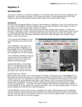
DEFINE TEMPLATE
Camera
Main Disk
/dwlii/template/
templateA.1
templateA.2
templateB.1
Main
CPU
Image
Processor
INTRODUCTION
This procedure is made for an interactive template definition. Before the program can
begin, a substrate from which a template will be made must be on the stage and infocus, and the camera with which the template will be processed, must be selected in
the Control Panel. Contrast and illumination should be as well as possible. For more
information on the image alignment by means of a template search, see Field
Alignment. The multiple sub-commands in this program are logically arranged and will
normally be executed from top to bottom.
44
HEIDELBERG INSTRUMENTS DWL 66FS User Guide Part II
Window 10
DEFINE TEMPLATE BUTTONS
• Load Template from File:
Shows the already defined templates that can now be selected. Be aware of the way
in which templates are stored on the main system hard disk
/USER/DWLII/TEMPLATE directory. Templates are stored under a name and a
number as an extension. The image processor only knows templates by their
number. For example, the Os9 directory will show files in a manner as such:
Calibr.1
Calibr.2
Calibr.3
XLD5050r.1
XLS5050x.1
After selection of a file - Calibr.1, Calibr.2, or Calibr.3, all templates stating Calibr will
be loaded to the template locations represented by the corresponding number in the
extension. If only one template is defined, only one template will be loaded; thus,
selecting XLS5050.1 - for example, will cause a template to be loaded in template
register number 1.
• Box Position:
First step of a template definition sequence after the camera has been selected and
the object area where a template is to be defined is visible and not too close to the
edge of the monitor image. After selection, the image is frozen and a cross appears
in the center of the screen, which can be moved while holding down the left button of
45
HEIDELBERG INSTRUMENTS DWL 66FS User Guide Part II
the mouse in the white square. Fine adjustment can be done using the arrows at the
side of the square.
• Box Size:
After definition of template position, its size is set using the slides that appear. The
best template is relatively small, yet contains unique information for both axes.
• Save Template in IPC:
Saves the defined template in the RAM of the image processor card IC40 under the
number previously set with the template # checkbox.
• Test Template:
Tests a defined template on the current image.
cursor block in means of the following format:
The result is printed below the
FOUND TEMPLATE AT:
R-Fit = 0.7
Xabs=-914-325
Yabs= 644 230
The R-Fit value gives the reliability of the result; an R-Fit of 1 is a perfect match. For
each axis’ the absolute template position in tics is shown, followed by the template
position in camera pixels.
If a template is not found an error message will appear. As a remedy, optimize
contrast, uniqueness, or lower Fit Level.
• Show Template:
Templates are stored in the IC40 as a series representation at various pixel
resolutions. The first search is done with a very course template image where
16x16 pixels are combined, followed by the next image with 8x8 pixels, etc. The
Show Template command is used to ensure that the information in a course image
still contains unique features so that a template may be found unambiguously.
Particularly if there is too much detail in a template, the low-resolution image may
contain only a blur and is then impossible to find unambiguously.
• Save Template on File:
All templates defined and stored in the IC40 under the numbers 1 through 4 can be
stored under a common name. After a [name] has been entered into the dialogue
box, the templates are stored under the names: <name>.1 through <name>.4 in the
Os9 directory /USER/DWLII/TEMPLATE.
• Template #:
Selects, which image processor template register, is used for storing and loading.
46
HEIDELBERG INSTRUMENTS DWL 66FS User Guide Part II
• Fit Level:
Using the arrows, the current fit level given in the box can be changed. The new fit
level will only be used for template testing unless it is being transferred to the
configuration file using the Fit Level Save button. The Fit Level decides the
reliability, that a result from a template search procedure that must have to be
accepted as O.K. Usually set to 0.8 (= 80% reliability); should never be lower than
0.6.
• Fit Level Save:
Causes the currently entered fit level to be stored into the configuration file, where
the value will be used for all future alignments - be careful when changing the Fit
Level.
47
HEIDELBERG INSTRUMENTS DWL 66FS User Guide Part II
CHAPTER 5 - METROLOGY
METROLOGY COMMANDS
A number of measurement procedures to quantify exposures are listed under Measure
in the main menu. Some of these commands are specifically developed to aid with the
measurement of parameters important for system specific adjustments and calibrations.
Most metrology commands require top illumination, which will lower quality
measurement of emulsion plates if using the high magnification objectives with 4mm
and 10mm focal lengths.
• Overlay:
Measures the relative positioning accuracy of two overlayed exposures on a single
plate by utilizing a number of models, such as box-in-box structures, etc.
• Distance:
Offers both an automatic and a manual metrology method for measuring the
distances between two features on a substrate.
• Positions:
Measures die-to-die alignment of a feature in order to ensure that the machine
coordinate system is linear and orthogonal.
• Linewidth:
Measures and analyzes the line width of a feature based on its video profile.
• Pitch, Stitching, Edge:
Measures the distance between two identical features by associating video profiles
of the images and then searching for the maximum in the correlation function.
48
HEIDELBERG INSTRUMENTS DWL 66FS User Guide Part II
OVERLAY MEASUREMENTS
Figure 5
INTRODUCTION
The purpose of overlay measurements is to determine the position shift between two
printed layers. To use the measurement methods offered under this command, specific
structures must be written as shown in Figure 5, where the red structures are written in
one layer, while the blue structures are part of the other layer. Overlay measurements
are designed to measure the registration between these two layers. There are two
different models:
• LARGE BOX in BOX METHOD:
Two lines of equal thickness are written on two layers. For the measurement, boxes
must be defined over these lines, two for -X and two for -Y. Within each of these
boxes the pitch, or distance between the two lines is measured. Overlay is
calculated by the difference between pitches. The Large Box in Box structure is
usually greater than the micro-camera field so the stage will move to each
measuring box before doing a pitch measurement.
• SMALL BOX in BOX METHOD:
The Small Box in Box structure consists of two box shaped areas placed within
each other. Measuring symmetry axes and comparing the differences will determine
the overlay.
49
HEIDELBERG INSTRUMENTS DWL 66FS User Guide Part II
Window 12
OVERLAY MEASUREMENTS - FILE COMMANDS
• Load:
Loads an already existing measurement file, which must have the extension ".msr",
and is normally found in the directory \MEASURE. Upon loading, a model option is
read from the file and is automatically switched on. After loading, a window will
appear requesting that the operator, “Point to the reference site,” to which all
recorded measurement positions will correspond. If the measurement method is
executed automatically through a Job file, the chosen reference site can also be the
alignment site of the respective field.
• Save Measurement:
Saves the current measurement method under a requested file name. This
measurement method can then be reloaded later or used within an automatic
measurement procedure. If a reference site was not previously marked, a window
will appear requesting to “choose a reference site”.
• Exit:
Closes the Overlay Measurements window (Window 12).
OVERLAY MEASUREMENTS - RESULTS COMMANDS
After a measurement series has been made, results may be inspected and saved using
the Results commands.
• View and Save:
Loads an editor with the current measurement results. The file can then be saved
as a text file within the editor.
• To Excel:
Copies the measurement results to the Clipboard. These can now be copied into
another application by pressing Control-V, or highlighting the Paste Function. In this
50
HEIDELBERG INSTRUMENTS DWL 66FS User Guide Part II
way, data can e.g. be displayed and further processed using Microsoft Excel or any
other spreadsheet application.
MODELS
The result of an overlay measurement depends on the contrast of structures, which in
many cases is far from ideal; therefore, a number of measurement strategies have
been developed, where two fundamentally different principles are being used: Pitch
Measurement -determines the distance between two similar structures, and Center
Measurement -determines the main symmetry axis of a structure.
• Large Box in Box-X:
A Large Box in Box structure will consist of two frames with similar thickness’, each
written on a separate layer (as shown on the left-side in Figure 5). Upon set up, a
window will request the placement of a measurement box over two vertical lines at
one location (1). The distance between these lines will now be measured using the
pitch method. Next, the same box must be placed over the corresponding right side
of the alignment structure (2). The overlay is determined by the difference between
these distances. The stage will always move the location where the measurement
box has been placed to the center of the screen before a measurement is started.
• Large Box in Box-Y:
A Large Box in Box structure will consist of two frames with similar thickness’, each
written on a separate layer. Upon set up, a window will request the placement of a
measurement box over two horizontal lines at one location (3). The distance between
these lines will now be measured using the pitch method. Next, the same box must
be placed over the corresponding lower part of the alignment structure (4). The
overlay is determined by the difference between these distances. The stage will
always move the location where the measurement box has been placed to the center
of the screen before a measurement is started.
• Box in Box-XY Model1:
A Small Box in Box structure consists of a filled block, framed by a relatively thick
line. Comparing the symmetry axis of the small block with the symmetry axis of the
frame does a measurement. The size of the whole structure is typically between 10
to 20-microns.
• Box in Box-XY Model2:
Box in Box-XY Model2 is applied if there is a rather weak contrast, or if a structure
is covered with a layer of resist and only the edges of the structure are detectable.
Overlay is measured in a similiar way as with the Large Box in Box structure, but
without moving the stage to the measurement positions.
51
HEIDELBERG INSTRUMENTS DWL 66FS User Guide Part II
OVERLAY MEASUREMENTS BUTTONS
• Set Up:
Before a measurement can be executed it must be pre-programmed with the Set Up
model. Depending on which method has been selected, measurement boxes are
required to be placed over the structures, and then a series of measurements can be
made by continuation. Cancel Set Up model if sufficient measurements have been
made. Once Set Up is complete, the whole measurement process can be saved
and viewed in View Measurement Method under the Tools menu.
• Relative To..:
Before a measurement can be saved a reference position must be selected. If no
reference position is selected, then the current stage position will be used as a
reference position. For a local series of measurements the location of the first
structure is normally used as a reference point. If the measurement method is ready
to be used for automatic measurements in the Job file, the field alignment sight may
be used.
• Measure:
Starts the currently active measurement sequence.
• Results (Text Box):
The results text box, located on the lower right-hand side of Window 12, posts the
actual overlay results and at the end of the measurement averages appear. The
complete results can be viewed using the View and Save command.
• Exit
Closes the Overlay Measurements window (Window 12).
52
HEIDELBERG INSTRUMENTS DWL 66FS User Guide Part II
Example of an Overlay Measurement Method
A typical program should follow the format of the model below:
Method=Small Box in Box-XY
Camera=Macro
InnerBox-X=100
InnerBox-Y=100
OuterBox-X=200
OuterBox-Y=200
Reference=Center of First Structure
{
'Indicates start
0,0
'X,Y of 1. site
100,0
'X,Y of 2. site
200,0
'X,Y of 3. site
300,0
'X,Y of 4. site
400,0
'X,Y of 5. site
500,0
'X,Y of 6. site
}
'End of series
53
HEIDELBERG INSTRUMENTS DWL 66FS User Guide Part II
DISTANCE MEASUREMENTS
INTRODUCTION
The measurement of distances on a substrate can be small as to fall within a camera
image, or large as to encompass the entire stage travel range.
Precision of
measurement is enhanced by repeating several times and will result in additional
statistical information. The best values are obtained if automatic template recognition is
used for the real measurement.
54
HEIDELBERG INSTRUMENTS DWL 66FS User Guide Part II
Window 13
DISTANCE MEASUREMENT BUTTONS
• Set Up Measurement:
Before a distance measurement can be made, the two points to be measured must
be defined. A window will request the operator “to point to the first site” with the
cursor by means of the mouse, then repeat for the second site. Use the Control
Panel to move over large distances, for switching between cameras, and for the
adjustment of contrast, etc. Once the measurement has been setup, the distance
between the two points (or, sites) will be shown in microns.
• Goto Site 1:
Moves stage to the site of the first measurement point.
• Goto Site 2:
Moves stage to the site of the second measurement point.
• Repeat Measurement # times
Repeat measurement should be set to at least 5 times for a satisfactory
measurement accuracy.
• Repeat Measurement:
Starts a measurement series.
• Exit:
Closes Distance Measurements window (Window 13).
55
HEIDELBERG INSTRUMENTS DWL 66FS User Guide Part II
ALIGNMENT
Select either Manual mode, which is also used for Set Up, or the Use Template mode.
A template must be defined, before the Use Template mode may be chosen.
• Make Template:
Opens Define Template window. If the template defined here will only be used for
the current distance measurement, it would be sufficient to store the template in one
of the four buffers of the IPC module.
56
HEIDELBERG INSTRUMENTS DWL 66FS User Guide Part II
POSITION MEASUREMENTS
x5,y5
POSITIONS
x6,y6
x7,y7
x8,y8
x9,y9
+
+
+
+
+
+
+
+
+
+
REFERENCE
SITE
x1,y1
x2,y2
x3,y3
x4,y4
INTRODUCTION
Position measurements provide information, not only about distances, but angular
distortions or non-linearity over a substrate as well. Position measurements are
therefore an important tool for initial system calibration and exposure quality control.
57
HEIDELBERG INSTRUMENTS DWL 66FS User Guide Part II
Window 14
POSITION MEASUREMENTS - FILE COMMANDS
• Load:
Loads an already existing measurement file, which must have the extension ".msr",
and is normally found in the directory \MEASURE. Upon loading, a model option is
read from the file and is automatically switched on. After loading, a window will
appear requesting that the operator, “Point to the reference site,” to which all
recorded measurement positions will correspond. If the measurement method is
executed automatically through a Job file, the chosen reference site can also be the
alignment site of the respective field.
• Save Measurement:
Saves the current measurement method under a requested file name. This
measurement method can then be reloaded later or used within an automatic
measurement procedure. If a reference site was not previously marked a window will
appear requesting to “choose a reference site”.
• Exit:
Closes the Position Measurements window (Window 14).
POSITION MEASUREMENTS - RESULTS COMMANDS
After a measurement series has been made, results may be inspected and saved using
the Results commands.
• View and Save:
Loads an editor with the current measurement results. The file can then be
saved as a text file within the editor.
• To Excel:
Copies the measurement results to the Clipboard. These can now be copied into
another application by pressing Control-V, or highlighting the Paste Function. In this
58
HEIDELBERG INSTRUMENTS DWL 66FS User Guide Part II
way, data can e.g. be displayed and further processed using Microsoft Excel or any
other spreadsheet application.
MODELS
If the distribution of identical structures on a substrate should be measured, a template
or – if the structure is e.g., a cross – a field alignment method can be used. If the
positions of several different structures should be measured, this must be done either
manually or with several separate measurements relating to the same point of
reference.
• Using Field Alignment:
Uses current field alignment for position detection. Highlight Field Alignment
Method under Setup in the Main Menu.
• Using Template #1:
This method uses the template currently stored in buffer #1of the IPC for the
detection of structure positions. To define a new template, highlight Define Template
under Setup in the Main Menu.
• Manual:
In manual mode, the operator is prompted to “Point to the Site to be Measured” for
each structure position measurement, similar to the setup procedure.
POSITION MEASUREMENT BUTTONS:
• Set Up:
Before a Position Measurement may be done, the stage positions at which the
structures to be measured are well within the camera field must be determined to
program the measurement procedure. When the Set Up function is started the
operator is prompted to “Point to First Site” to be measured using the mouse and, if
necessary, the Control Panel. This has to be repeated for each structure to be
measured. Finish the measurement setup by choosing Cancel in the Define
Measurement dialogue box. Now the measurement method can be saved and
viewed in View Measurement Method under Tools in the Main Menu.
• Relative To..:
Before a measurement can be saved a reference position must be selected. If no
reference position is selected, then the current stage position will be used as a
reference position. For a local series of measurements the location of the first
structure is normally used as a reference point. If the measurement method is ready
to be used for automatic measurements in the Job file, the field alignment sight may
be used.
59
HEIDELBERG INSTRUMENTS DWL 66FS User Guide Part II
• Measure:
Starts the currently active measurement sequence.
• Results (Text Box):
The results text box, located on the lower right-hand side of Window 14, posts the
actual measurement result. The complete results can be viewed using the View and
Save command.
• Exit
Closes the Position Measurements Window (Window 14).
Example of a Position Measurement Method
A typical program should follow the format of the model below:
Method=
Camera=
Box Width=
Box Height=
Reference=
{
0,0
100,0
200,0
300,0
400,0
500,0
}
Using Template #1
Micro
0
0
Lower Left Corner of Pattern
'Indicates start
'X,Y of 1. site
'X,Y of 2. site
'X,Y of 3. site
'X,Y of 4. site
'X,Y of 5. site
'X,Y of 6. site
'End of series
60
HEIDELBERG INSTRUMENTS DWL 66FS User Guide Part II
LINE WIDTH MEASUREMENTS
INTRODUCTION
Linewidth measurements are done through the camera system where the video
camera must show the line structure to be measured either in X or in Y. Measuring the
diameter of a circle is possible by either lowering the box height, or tightening the width
of the box. The contrast should be clear, and if contrast is not clear, modify Lamp,
Gain and Offset of the camera to improve the contrast. Two of the available analysis
models are based on a linear fit to a small range of video signals around a requested
threshold value, followed by a determination of the intersection between the horizontal
threshold line and the fitted lines. Thereby, values are considerably more accurate than
just the camera pixel size. The third model determines the positions of the two signal
minima using a parabolic fit.
Window 15
61
HEIDELBERG INSTRUMENTS DWL 66FS User Guide Part II
LINEWIDTH MEASUREMENTS - FILE COMMANDS
• Load:
Loads an already existing measurement file, which must have the extension ".msr",
and is normally found in the directory \MEASURE. Upon loading, a model option is
read from the file and is automatically switched on. After loading, a window will
appear requesting that the operator, “Point to the reference site,” to which all
recorded measurement positions will correspond. If the measurement method is
executed automatically through a Job file, the chosen reference site can also be the
alignment site of the respective field.
• Save Measurement:
Saves the current measurement method under a requested file name. This
measurement method can then be reloaded later or used within an automatic
measurement procedure. If a reference site was not previously marked a window will
appear requesting to “choose a reference site”.
• Exit:
Closes the Line Width Measurements window (Window 15).
LINEWIDTH MEASUREMENTS - RESULTS COMMANDS
After a measurement series has been made, results may be inspected and saved
under Results commands.
• View and Save:
Loads an editor with the current measurement results. The file can then be saved as
a text file within the editor.
• To Excel:
Copies the measurement results to the Clipboard. These can now be copied into
another application by pressing Control-V, or highlighting the Paste Function. In this
way, data can e.g. be displayed and further processed using Microsoft Excel or any
other spreadsheet application.
MODELS
• LineWidth-X
Select the X method for vertical lines.
• LineWidth-Y
Select the Y method for horizontal lines.
62
HEIDELBERG INSTRUMENTS DWL 66FS User Guide Part II
• Thick LineWidth-X:
Selects the measurement method for thick verticle lines (larger than ½ monitor
image).
• Thick LineWidth-Y:
Selects the measurement method for thick horizontal lines (larger than ½ monitor
image).
PROPERTIES
• Inside:
Analysis is done by looking for the intersection between the video profile and the
threshold level, starting from the center of the box.
• Outside:
Analysis is done by looking for the intersection between the video profile and the
threshold level, starting from the two edges of the measurement box.
• Minimum:
Beginning at the center of the measurement frame, searches for the two extremes.
The location of extremes is found by locally fitting a parable.
• Threshold=
Enter a value between 0 and 100% of the amplitude of the video profile. For most
purposes the value should be between 25% and 50%.
• Repeats=
The measurement method averages over all the video lines within the height, or
width of a box before making threshold analysis. In addition, the whole measurement
can be repeated and averaged a number of times by entering the desired number of
repeats in this box. However, no statistical information is deduced from this type of
averaging.
LINEWIDTH MEASUREMENTS BUTTONS
• Set Up:
Before a measurement can be executed it must be pre-programmed with the Set Up
model. Depending on which method has been selected, measurement boxes are
required to be placed over the structures, and then a series of measurements can be
made by continuation. Cancel Set Up model if sufficient measurements have been
made. Once Set Up is complete, it can be saved and viewed in View Measurement
Method under the Tools menu.
63
HEIDELBERG INSTRUMENTS DWL 66FS User Guide Part II
• Relative To..:
Before a measurement can be saved a reference position must be selected. If a
current reference position is not manually selected, then an arbitrary location may
automatically select the current position. For a local series of measurements the
location of the first structure is normally applied. If a method for including a fully
automatic program is pre-prepared, the alignment site can be employed.
• Measure:
Starts the currently active measurement sequence.
• Results (Text Box):
The results (text box), located on the lower right-hand side of Window 15, posts
the actual measurement results and at the end of the measurement averages
appear. The complete results can be viewed using the View and Save command.
• Exit:
Closes the Linewidth Measurements window (Window 15).
Example of a Linewidth Measurement Method
A typical program should follow the format of the model below:
Method=LineWidth-X
Camera=Micro
BoxWidth=100
BoxHeight=84
Model=Inside
Threshold=50
Repeats=1
Reference=Low Left Corner PFM Pattern
{
'Indicates start
0,0
'X,Y of 1. site
100,0
'X,Y of 2. site
200,0
'X,Y of 3. site
300,0
'X,Y of 4. site
400,0
'X,Y of 5. site
500,0
'X,Y of 6. site
}
'End of series
64
HEIDELBERG INSTRUMENTS DWL 66FS User Guide Part II
PITCH MEASUREMENTS
INTRODUCTION
In many cases it is important to measure the distance between two structures, located
relatively near to each other. If such structures are identical in appearance, the
distance being measured is uniquely defined by a numerical comparison of the two
video profiles of each structure. A cross correlation will yield the distance with an
extremely high repeatability.
• PITCH MEASUREMENTS:
The pitch measuring method is applied for finding the horizontal distance of pairs of
vertical lines or for finding the vertical distance of pairs of horizontal lines. This method
may be extended to measure whole sets of equidistant lines.
• STITCHING MEASUREMENTS:
Determines the vertical position of two horizontal lines or the horizontal distance of two
vertical lines. This method and is designed to run DWL stitching performance
measurements in both X and in Y, using the system test pattern.
• EDGE MEASUREMENTS:
The measurement of edge roughness in an exposed structure. The average position of
a vertical line is measured at a number of positions. Each position is determined by the
location of the maximum in the cross-correlation function of the local video profile
through its mirror image. The RMS deviation of a fit through these position
measurement results will determine edge roughness.
65
HEIDELBERG INSTRUMENTS DWL 66FS User Guide Part II
Window 16
PITCH MEASUREMENTS - FILE COMMANDS
• Load:
Loads an already existing measurement file, which must have the extension ".msr",
and is normally found in the directory \MEASURE. Upon loading, a model option is
read from the file and is automatically switched on. After loading, a window will
appear requesting that the operator, “Point to the reference site,” to which all
recorded measurement positions will correspond. If the measurement method is
executed automatically through a Job file, the chosen reference site can also be the
alignment site of the respective field.
• Save Measurement:
Saves the current measurement method under a requested file name. This
measurement method can then be reloaded later or used within an automatic
measurement procedure. If a reference site was not previously marked, a window
will appear requesting to “choose a reference site”.
• Exit:
Closes the Pitch Measurements window (Window 16).
PITCH MEASUREMENTS - RESULTS COMMANDS
After a measurement series has been made, results may be inspected and saved using
the Results commands.
• View and Save:
Loads an editor with the current measurement results. The file can then be saved as
a text file within the editor.
• To Excel:
Copies the measurement results to the Clipboard. These can now be copied into
another application by pressing Control-V, or highlighting the Paste Function. In this
66
HEIDELBERG INSTRUMENTS DWL 66FS User Guide Part II
way, data can e.g. be displayed and further processed using Microsoft Excel or any
other spreadsheet application.
MODELS
• Stitching-X:
Measures the distance between two vertical lines, on both left and right sides of a
stripe border, and will repeat the measurement in other locations on the substrate, if
required. The RMS deviation of the results from the resulting average will determine
stitching quality in -X.
• Stitching-Y:
Measures the vertical distance between the sections of two horizontal lines, on both
left and right sides of a stripe border, and will repeat the measurement in other
locations on the substrate, if required. The RMS deviation of the results from the
resulting average will determine stitching quality in –Y. This value depends on the
stage velocity and therefor must be minimized by optical adjustment for each
configuration individually.
• Pitch-X:
Compares the distance between two vertical lines or a row of equidistant lines over a
programmed area.
• Pitch-Y:
Compares the distance between two horizontal lines or a row of equidistant lines
over a programmed area.
• Edge-X:
Determines the roughness of a vertical edge due to position fluctuations, but can
only be applied to a comparatively thin vertical line. The result is insensitive for line
width fluctuations.
• Edge-Y:
Determines the roughness of a horizontal edge due to position fluctuations, but can
only be applied to a comparatively thin horizontal line. The result is insensitive for line
width fluctuations.
PITCH MEASUREMENTS BUTTONS
• Set Up:
Before a measurement may be executed it must be pre-programmed with the Set Up
model. Depending on which method has been selected, measurement frames are
required to be placed over the structures, and then a series of measurements can be
made by continuation. Cancel Set Up model if sufficient measurements have been
67
HEIDELBERG INSTRUMENTS DWL 66FS User Guide Part II
made. Once Set Up is complete, the method programmed may be saved and viewed
in View Measurement Method under Tools in the Main Menu.
Example of a Pitch Measurement Method
A typical program should follow the format of the model below:
Method=Pitch-X
Camera=Micro
BoxWidth=100
BoxHeight=275
BoxDistance-X=201.44098189792
Reference=Lower Left Corner of PFM Pattern
{
'Indicates start
0,0
'X,Y of 1. site
100,0
'X,Y of 2. site
200,0
'X,Y of 3. site
300,0
'X,Y of 4. site
400,0
'X,Y of 5. site
500,0
'X,Y of 6. site
}
'End of series
• Relative To..:
Before a measurement can be saved a reference position must be selected. If no
reference position is selected, then the current stage position will be used as a
reference position. For a local series of measurements the location of the first
structure is normally used as a reference point. If the measurement method is ready
to be used for automatic measurements in the Job file, the field alignment sight may
be used.
• Measure:
Starts the currently active measurement sequence.
• Results (Text Box):
The results text box, located on the lower right-hand side of Window 16, posts the
actual measurement result. The complete results can be viewed using the View and
Save command.
• Exit:
Closes the Pitch Measurements window (Window 16).
68
HEIDELBERG INSTRUMENTS DWL 66FS User Guide Part II
CHAPTER 6 - TOOLS
TOOLS
A number of tools have been prepared for the further processing and display of
collected data.
• Analyse Report for Alignment:
Extracts relevant alignment information from a job report file, where the data can
then be sent to a spreadsheet for further evaluation.
• Analyse Report for Measurement Results:
Extracts relevant measurement information from a job report file, where the data can
then be sent to a spreadsheet for further evaluation.
• View Job Log:
Displays content of the Job Log File.
• View Measurement Method:
Displays present measurement method and will enable an operator to edit the
method (i.e., to manually add more measurement points).
69
HEIDELBERG INSTRUMENTS DWL 66FS User Guide Part II
ANALYSE REPORT
INTRODUCTION
After each exposure and measurement procedure, a Report file is produced containing
information regarding the inspection and qualification of an exposure. Since all the
various information stored in a Report file are printed in a sequential order, extracting
specific data may be necessary before further evaluation may be done. This data
extraction may be done either manually or automatically using the Analyse Report
window (Window 17).
Window 17
70
HEIDELBERG INSTRUMENTS DWL 66FS User Guide Part II
ANALYSE FOR… FUNCTIONS
• Alignment Results:
Extracts and groups all relevant alignment data into a table to be processed in
Microsoft Excel.
• Measurement Results:
Extracts and groups all measurement results into a table to be processed in
Microsoft Excel. The Measurement menu is followed by all stage positions and
current measurement results used to produce a plot of measurement results as a
function of the location on the substrate.
• Analyse For... (Text Frame):
Displays which option for report file data extraction is currently active.
ANALYSE REPORT BUTTONS
• Open:
Directly after an exposure, or measurement, the last report made is loaded by default
and it is not necessary to open a file. The Open command will analyze a previously
written report. All report files have the extension .rpt and are normally recorded in
their corresponding Job directory.
• Edit:
Loads the requested data under a different name into an editor where it may be
inspected and saved.
• To Clip Board:
Writes extracted data to the Clipboard. It can then be pasted into an editor or
spreadsheet program (i.e., Microsoft Excel) for inspection and further analysis.
Without exiting the DWL menu, start the other application and press Control-V, or
use the Paste command available within the application. The data will be loaded
onto the current spreadsheet.
• Exit:
Closes the Analyze Report window (Window 17).
71
HEIDELBERG INSTRUMENTS DWL 66FS User Guide Part II
VIEW JOB LOG FILE
VIEW JOB LOG
If Job Log is highlighted in the Run Job submenu, then the name of the current job,
start time, and stop time for each exposure or automatic measurement is entered in the
file "C:\VBMENU\WINDWL\JOBLOG.TXT". The View Job Log function loads this file
into the Windows Notepad where it can be inspected, altered, printed or saved under
another name, or on another medium. The content of the Job Log is useful for
accounting purposes.
72
HEIDELBERG INSTRUMENTS DWL 66FS User Guide Part II
VIEW MEASUREMENT METHOD
VIEW MEASUREMENT METHOD
Opens the Windows Default Editor (usually Notepad) for inspecting, editing, saving,
and printing measurement method files. Once a specific measurement method is
created, the list of measurement locations can be extended using the editor, which is
easier than having to prepare each individual measurement point manually. To
construct a measurement location table for an extremely large number of
measurements, a spreadsheet program like e.g. Microsoft Excel can be used, but be
careful to use the correct format when transferring the coordinate sets to the
measurement method.
73
HEIDELBERG INSTRUMENTS DWL 66FS User Guide Part II
CHAPTER 7 - SERVICE
SERVICE COMMANDS
• Debug Window:
Monitors communication between the User PC and the DWL Main CPU. This
function is only to be used during a test, since it will considerably slow down the
performance of the entire DWL system.
• View OS9 Config:
Shows current machine configuration parameters.
• DWL Control Panel (F9):
Opens window with manual controls for most system functions, particularly stage
initialization and focus.
• Edit Configuration File:
Opens editor to check and edit current system configuration. Provides access to the
Configuration Change window as well as the windwl.ini menu startup file for
viewing.
• Video Calibration
Calibrates the micro- and macro-camera position against the interferometer. This
procedure must be repeated whenever modifications to the optics system have been
made.
• Reset Stage:
Initializes the stage after confirmation from the operator by moving it back into the
Home position and resetting the interferometer coordinate system. Same function as
the Stage Reset Option in the Control Panel menu.
74
HEIDELBERG INSTRUMENTS DWL 66FS User Guide Part II
SMALL TALK COMM DEBUG AND OS9
COMMANDS
INTRODUCTION
The DWL main system is controlled by a number of programs running concurrently. The
User PC simply generates command strings in a useful sequence where decisions
depend on a response from the main system. Communication usually runs along one
serial COM port, and before the system can be operated, the PC port must be logged in
as a user for the OS9 operating system, by clicking on the Mini Terminal icon
located below the main menu toolbar. User name and password are factory preset to:
“dwlii”. If the PC is not logged in or there is no connection to the system, opening the
Debug Window will display commands that would have been sent by the PC to the
DWL system.
75
HEIDELBERG INSTRUMENTS DWL 66FS User Guide Part II
Window 18
OS9 COMMANDS
This is only an excerpt of the most common functions. If the DWL system is connected
and the PC is logged on, detailed information on every OS9 command may be obtained
by opening the Mini Terminal window and typing in commands with the -? option.
• General Commands:
adjust_fi
Function:
download / create frequency & intensity data for ECU
Syntax:
adjust_fi {[<opts>] <filename>} [<opts>]
Options of interest:
-c
Create new frequency-intensity database file
-u
Update from existing database
-p
adjust Intensity Profile
-I
Init with default values
-s[=][<fac>]
Scale Int.Profile to <fac>%
-t[=][<range>]
Defl.Area Test (+/-<range>%)
<range> 0-100 (%)
-d[=]<hex>
debug flag:
$0800 program variables
$0400 Parser
expodie
Function:
Exposure Control Program
Syntax:
expodie [<opts>] {<design> [<opts>]}
Options of interest:
-i[=]<value>
Exposure Intensity (0-100)[%]
-s[=]<name>
list of stripes
-x[=]<value>
X position (nm)
-y[=]<value>
Y position (nm)
-k
keep SDist from expose.cfg
-d[=]<hex>
debug flag:
$0800 program variables
$0400 Parser
76
HEIDELBERG INSTRUMENTS DWL 66FS User Guide Part II
$0100 Messages
$0004 calculated values
hw
Function:
User Interface for DWL hardware
Syntax:
hw [<opts>] [<cmds>]
Commands:
ifstat
ckeck status of IF-System
ifreset
reset IF-System
hecd[+ / -]
open / close HeCD shutter
afix[+ / -]
fix / release Auto Focus
movz
display actual <zpos>
movz=<zpos>
move write head to <zpos>
movz[+|-]<zsteps>
move write head +|- <zsteps>
movz:=<zpos>
set write head position to <zpos>
adc.<cname>
read value from ADC <cname>
hilo
(CH4)
piezo
(CH5)
intens (CH7)
IN_0
(CH0)
IN_1
(CH1)
IN_2
(CH2)
IN_3
(CH3)
IN_4
(CH6)
dac.<cname>=<value> set <value> for DAC <cname>
lamp…(CH_A)
defoc…(CH_D)
OUT_0…(CH_B)
OUT_1…(CH_C)
Options of interest:
-d[=]<hex>
debug flag:
$0800 program variables
$0400 Parser
init_dwl
Function:
initialize DWL data structures
Syntax:
init_dwl [<opts>]
Options of interest:
-f[=]<file>
configuration file (default: dwl.cfg)
-u
force update with conf. file
-r[e|u]
remove installed memory modules & events
e
remove only events
u
unlock all events
-d[=]<hex>
debug flag:
$0800 program variables
$0400 Parser
77
HEIDELBERG INSTRUMENTS DWL 66FS User Guide Part II
$0100 Messages
mov
Function:
Interface to stage control
Syntax:
mov [<opts>]
Options of interest:
home
move stage to home position
-u
force move home
[x/y].
show x/y position in nm
[x/y]:=<num>
set x/y abs. position to <num> nm
[x/y]:[+/-]<num>
set x/y pos. to actual [+/-]<num> nm
[x/y][+/-]<num>
move x/y [+/-]<num> nm from act. pos.
[x/y]=[+/-]<num>
move x/y to pos. [+/-]<num> nm
-d[=]<hex>
debug flag:
$0800 program variables
$0400 Parser
$0100 Messages
$0080 Communication
$0008 Events
• Image Processing Commands:
ipc
Function:
execute image processor commands
Syntax:
ipc <command>
Commands:
dc <xpix> <ypix>
activate
cursor
at
position
<xpix>,<ypix>enter -1 to deactivate
cursor, unit is monitor pixels
db <xwidth> <ywidth>
set box size to <xwidth>x<ywidth> (unit
pixels)
offset <val>
set camera intensity offset to <val>
(range 0…255)
gain <val>
set camera gain to <val> (range 0…255)
snap
freeze image
live
start continuous image grabbing
cam [0 / 1]
switch to macro / micro camera
width
Function:
Measure width of video profile
Syntax:
width <parameter> <parameter> ...
Parameters:
axis [x/y]
measurement orientation, can be 'x' or 'y'
xpos [pixel]
left border of measurement box (0..639)
ypos [pixel]
upper border of measurement box (0..511)
xwidth [pixel]
width of measurement box (0..320)
78
HEIDELBERG INSTRUMENTS DWL 66FS User Guide Part II
ywidth [pixel]
repeat [count]
model [to|ti|m]
epsilon [pixel]
threshold [percent]
height of measurement box (0..256)
number of accumulations (>1)
measurement algorithm, can be
to (threshold outside), or
ti (threshold inside)
interpolation range (0..7), usually 2 gives best
results
threshold (0..100)
center
Function:
Measure position of symmetry axis of video profile
Syntax:
center <parameter> <parameter> ...
Parameters:
axis [x|y]
measurement orientation, can be 'x' or 'y'
xpos [pixel]
left border of measurement box (0..639)
ypos [pixel]
upper border of measurement box (0..511)
width [pixel]
width of measurement box (0..320)
height [pixel]
height of measurement box (0..256)
repeat [count]
number of accumulations (>1)
grfx [0/1]
switch off / on graphics
Remark: The program generates a debug file named result.wks; this file
contains intermediate results and the graphs of the intensity
profile, the correlation function and the square fit function
pitch
Function:
Measure distance between two similar video profiles
Syntax:
center <parameter> <parameter> ...
Parameters:
axis [x|y]
measurement orientation, can be 'x' or 'y'
xpos [pixel]
left border of measurement box (0..639)
ypos [pixel]
upper border of measurement box (0..511)
width [pixel]
width of measurement box (0..320)
height [pixel]
height of measurement box (0..256)
repeat [count]
number of accumulations (>1)
estimate [pixel]
nominal or estimated pitch
tload
Function:
Syntax:
Load templates from disk to ipc
tload -p=<path> -w=<file>
Function:
Syntax:
Save templates to disk
tsave -p=<path> -tn=<template#> -w=<file>
tsave
79
HEIDELBERG INSTRUMENTS DWL 66FS User Guide Part II
VIEW OS9 CONFIGURATION
This option uploads some of the machine configuration parameters currently loaded on
the DWL66 and display them in a text box. In addition, it performs some status checks
on OS9 as well as within the menu and displays the results. The function started by this
menu option is automatically executed whenever the menu is started or the
configuration is changed. On OS9, the parameter and status check resulting in the
displayed values is executed by using the OS9 command init_dwl -v. This is a very
helpful tool for troubleshooting.
OS9 PARAMETERS
The character in square brackets shown behind some of the parameters denotes the
data type of the parameter for consistency check against the value (g - double, f - float,
? - boolean, d - decimal, x - hexadecimal).
• MAGIC
Internal parameter denoting the structure of the main data module DWL_inimod for
consistency check with program versions. If versions don't match, the error message
here would be: "init_dwl: Can't accept DWL_inimod"
• Configuration
Currently active configuration.
80
HEIDELBERG INSTRUMENTS DWL 66FS User Guide Part II
• TickSize
Length unit of the interferometer system in nm. Standard value is 9.8875nm.
• ClockSize
System clock period in ns. Standard 40ns (= 25 MHz).
• Speed
Stage speed during exposures in mm/s. Scales with write head and depends on
exposure mode.
• BiDirScan
Flag for activation of bidirectional writing. Values OFF (no bidirectional functionality) /
ON (bidirectional writing configured).
• YPreTrigger
Trigger delay/advance in ns for the backward written stripes during bidirectional
writing. If the system is not configured for this mode, the parameter is noted as "not
initialized".
• YPreScn
Acceleration distance during exposures, in µm. Scales with write head.
• XField
Pixel period in x in system clock ticks (= period of data clock). Standard value is 5
clock ticks, which usually means a pixel period of 5*40ns = 200ns, corresponding to
a data clock frequency of 5 MHz.
• XdiP
Distance between interpolated pixels (see IPix) on the substrate, in nm. Scales with
write head and depends on write mode.
• XPixVld
Scan width in pixels. Standard is 100 pixel, leading to a scan time of 200ns * 100 =
20µs. When calculating the scan rate, a dead time of 5µs for data loading and ramp
restart has to be added to this value.
• IPix
Interpolated subpixels per scan. Each pixel is in x divided into several (XPixVld/IPix)
subpixels to determine the value on the interpolation scale for the pixel. Standard
value is 400.
81
HEIDELBERG INSTRUMENTS DWL 66FS User Guide Part II
• YField
y-distance between scans in interferometer ticks. Configuration dependent. During
an exposure, while the stage is moving continuously, a scan is triggered every YField
ticks.
• ECU_Base / EMU_Base / DETC_Base
Base adresses and adress room regions set for communication with the related
system hardware components.
• EMU_Size
Memory size of the Exposure Memory Unit.
• AutoFocus
Flag denoting whether an autofocus system is configured. Possible values: YES / NO
• ModeG32
Flag denoting whether grascaling is configured. Possible values YES / NO.
• TanPhiX
Tangens of the orthogonality correction angle. Corrects for the angular misalignment
between the interferometer mirrors with respect to a perfectly orthogonal setup.
• IF-Type
Interferometer type installed (denoted by manufacturer name). Possible values:
RENISHAW / ZYGO / HP
• DefTPos
Default focus position of the backside camera system lens in motor steps relative to
retracted position. Negative number.
• DefDPos
Default tilt position of deflector mount during exposures. Configuration dependent.
• LasOnWait
Configuration of wait time in seconds before the laser can be switched on again after
a software controlled switch off. Only usable for lasers connected to the OS9 system.
Usually not used (entry "not initialized").
SYSTEM STATUS
• iflags
Internal flags for interferometer initialization values
82
HEIDELBERG INSTRUMENTS DWL 66FS User Guide Part II
• Module Valid
Checks if the main data module DWL_inimod is OK. Possible values: YES / NO
• Events Valid
Shows whether event initialization has taken place since the last system startup
(prevents double call of the same routine by different programs).
• IF-System OK
Interferometer system status check. Possible values: YES / NO. In case of problems,
please consult the troubleshooting section of User Guide I.
• Stage Cont. Init.
Flag denoting whether the stage controller was initialized since the last system
startup.
• Move Home done
Flag denoting whether a homing procedure has been performed since the last
system startup.
• Valid Config. found
Shows if the requested configuration file was found and is valid. Possible values:
YES / NO.
• Adjust FI done
Denotes whether the data imaging frequency-intensity table for the current
configuration was loaded successfully. Possible values: YES / NO.
• hw_flags
Internal flags for state of system hardware.
83
HEIDELBERG INSTRUMENTS DWL 66FS User Guide Part II
DWL CONTROL PANEL
INTRODUCTION
The most important commands for direct, interactive operation are made available
through the DWL Control Panel (Window 19), featuring options for stage control,
focusing, simple measurement capabilities, camera adjustments, etc. The DWL
Control Panel can be opened by clicking on the Control Panel icon
the main menu toolbar, or by highlighting the DWL Control Panel
under the Service heading.
located below
F9 submenu
Window 19
84
HEIDELBERG INSTRUMENTS DWL 66FS User Guide Part II
STAGE BUTTONS
• Initialize
Initializes stage coordinates, where the writehead moves until it reaches
its upper endswitch and the XY stage moves to the home position. After
setting the X and Y position registers to zero, the stage moves to the
center position.
• Load Position:
This function performs a stage initialization as described above and then
moves the stage to the load position.
• Set X=0, Y=0:
Sets both X and Y coordinates to zero at the current position.
• Move To 0, 0:
Moves stage to the latest set 0,0 position
• Move To..:
Moves stage to an absolute X / Y position, where the required position is
entered in microns.
• Move...:
Moves stage to a relative X / Y position, where the required position is
entered in microns.
CAMERA BUTTONS
• Camera:
Selects micro- or macro-camera and correspondingly, adjusts the video
values for the selected camera to the latest values that were used.
85
HEIDELBERG INSTRUMENTS DWL 66FS User Guide Part II
WRITEHEAD BUTTONS
• Focus:
Moves down the writehead until it reaches the airflow auto-focus position
while continuously displaying the current Z-stage position. Pressing the
Cancel button will abort the Focus command if there are any doubts
regarding the correct position of the airflow auto-focus. The nozzle can
be permanently damaged if the stagemoves while performing the Focus
function, or if focusing is done on the edge of a substrate.
• Lens Up:
Moves the writehead into its upper end position. Use if there are doubts
about the surface flatness of the substrate and a test focusing on
different locations and comparing the z-values must be done.
• Move Z:
The writehead moves up or down while one of the z-buttons is pressed.
Using the arrow buttons, choose between slow or fast movement. It is
not possible to move below the airflow focus position.
CAMERA SELECTION / BACKSIDE FOCUSING
The camera label shows which camera ist currently selected. To
change between the low resolution macro- and the high resolution
micro-camera, click on the label.
Systems equipped with backside alignment: If the BS check box is checked, the label
can be used to select the macro- or micro-camera of the backside alignment system. In
addition, buttons for backside focussing appear:
Focus - moves the backside lens to the preset position for
backside imaging.
Down - the lens is moved down into the retracted position
Up 1 step / 10 steps - these buttons can be used to manually
move the backside lens towards the substrate and check for
the optimum focussing position.
SCROLL SLIDES
• DeFoc (Defocus):
Slide to set a certain offset between the airflow focus position and the required
optical focus. Value range is 0 to 4095. (200 units are approximately 1µm).
86
HEIDELBERG INSTRUMENTS DWL 66FS User Guide Part II
• Lmp (Lamp):
Slide to choose lamp intensity. Value range is 0 to 4095.
• Gn and Off (Gain and Offset):
Control gain and offset of the image processing system and are normally set to 128.
Only slide to a different setting if it is necessary to increase contrast.
MENU BAR
• File:
−
−
Load / Save Panel Status:
Will refresh Configuration File with new values- or reload previous values.
Quit:
Closes Control Panel (Window 19).
• Options:
−
−
Microns / nm/steps:
Check desired metric representation of the stage (microns/nm) and write lens
(microns/steps) position. The Result Panel displays selected metrology.
Relative / Absolute
Check desired representation of the stage position. The Result Panel displays
u a
selected representation. If Relative representation is marked then a 0 button
will appear and the stage position window is reset. Marking Absolute will return
the display to absolute stage position coordinates. This feature can be used for
rough distance measurements.
• Stage:
−
−
−
−
−
Initialize:
Initializes stage coordinates, where the writehead moves until it reaches its
upper endswitch and the XY stage moves to the home position. After setting the
X and Y position registers to zero, the stage moves to the center position.
Load Position:
This function performs a stage initialization as described above and then moves
the stage to the load position.
Test Init Quality:
Checks on offsets in the stage coordinate system. This function is automatically
performed every time a stage initialization is done. There, if the result is above a
limit set in the configuration, the stage is re-initialized until the offset is within the
limit.
Reset:
Initializes the stage after confirmation from the operator by moving it back into
the Home position and resetting the interferometer coordinate system.
Motor ON / OFF:
Switches linear motors on or off.
87
HEIDELBERG INSTRUMENTS DWL 66FS User Guide Part II
−
−
−
−
−
−
−
Move...:
Moves stage to a relative X / Y position, where the required position is entered in
microns.
Move to...:
Moves stage to an absolute X / Y position, where the required position is entered
in microns.
Move to 0, 0:
Moves stage to the latest set 0,0 position
Set X=0 Y=0:
Sets both X and Y coordinate values of current position to the values given.
Set X=_, Y=_:
Sets coordinate values of current position to the values given.
Set rot = 0:
Resets rotation angle to 0 (including any rotational correction.
Find Plate Center:
Starts an automatic sequence that detects the positions of the plate edges and
calculates the plate center position from that. Write lens should be focused at
approximate center before starting this sequence.
• StepSize:
Shows field size, as extracted from the current Map file, which will be used for the
fieldwise stage move function. Also shows current stepsize for stepwise motions,
which can be changed by clicking on the numbers.
• Positions:
Offers the possibility to memorize a position, or move directly to one of the
memorized positions by highlighting them in the list. Up to 8 positions can be stored
in the list. To memorize a position, move the stage to it, click on "Set Position", and
choose the list place for the position. The current coordinates will then show up in the
list at the position that was indicated.
Note: The coordinates are stored in the user coordinate system, so if the origin
changes, the stored position will also be in a different place on the stage.
• View:
−
Standard / Advanced:
Selecting Advanced gives access to some more advanced controls.
CAUTION: These functions should only be used by experienced users, as wrong
usage may cause severe damage to the system, e.g. through nozzle crash.
MOVEMENT OPTIONS
• Move:
Stage movement with arrows is done in steps that depend on the distance from the
center in which the arrow is clicked on. The farther out the click position is, the larger
88
HEIDELBERG INSTRUMENTS DWL 66FS User Guide Part II
the step will be, up to a maximum of about one camera picture. The distance value
of the maximum stepsize is calculated from the camera calibration value of the
current writehead configuration for the active camera.
• Step:
Jumps the stage over preset steps independent of click-position. Set the stepsize
with the StepSize Menu function.
• Field:
Jump from field to field as defined in the exposure map.
X-Y STAGE
• ARROWS:
With each left-click on one of the arrow fields the stage moves according to the
mode chosen in the Movement Options frame. A right-click moves in the opposite
direction.
• CENTER ARROW:
Moves the stage back to the previous position.
89
HEIDELBERG INSTRUMENTS DWL 66FS User Guide Part II
EDIT CONFIGURATION FILE
INTRODUCTION
There's at least one configuration file for each writehead located in the directory
VBMENU/WINDWL. These contain important parameters about the system hardware,
general menu settings, exposure settings etc.
NOTE: Some entries are set manually during setup and calibration, while others
are continuously modified by the menu to memorize settings etc..
Highlighting Edit Configuration File under Service in the main menu will open the
current configuration file in the Edit Configuration File window (Window 20):
Window 20
This window can be used for viewing as well as editing the parameter values.
CAUTION:
Only advanced users should modify these settings, as some of them could
cause damage to the system if set incorrectly!
90
HEIDELBERG INSTRUMENTS DWL 66FS User Guide Part II
EDIT CONFIGURATION FILE BUTTONS
• Save As:
Saves current configuration file under a new name.
• Change:
Opens the Choose Configuration window (also accessible from configuration
information box in the main menu toolbar), in which a new configuration file can be
loaded.
In the Choose Configuration window, the left text box shows which write head
configurations are available. Once a write head has been chosen, the right text box
displays the write modes available for the chosen write head.
− Cancel:
Closes Choose Configuration window and returns to the main menu.
− Load it!:
Menu will restart with the new configuration.
• WinDwl.ini
The WinDwl.ini button opens the file WinDwl.ini, which only consists of two lines
and sets the configuration file for the menu, which will be loaded at the menu startup.
This file is automatically created whenever the configuration file is changed. The first
line shows, which write head configuration was loaded, last.
The configuration should not be changed manually. There is a different configuration
file available for each writehead, i.e., the file 04mm.cfg is the configuration file for a
4mm writehead, the file 20mm.cfg for a 20mm writehead. The second line shows
which of the available write modes were chosen for the chosen write head.
• CANCEL
Closes Edit Configuration File window (Window 20) without testing for changes or
updating the system.
91
HEIDELBERG INSTRUMENTS DWL 66FS User Guide Part II
• OK
Accepts modifications, saves changed configuration file, and resets all system
parameters accordingly.
PARAMETERS
Relevant menu parameters and their functions are:
• Info:
This parameter determines the File Info line shown in Choose Configuration
window if the file is highlighted.
• Mode=
Mode=0 means DWL is available
Mode=1 can be used to test most functions
• MenuPort=
Indicates which COM port is being used for communication between the menu and
the system
• AOMint=
Type of intensity setting technique, which depends on a machine's hardware
Usually set to 1 for newer machines
• LaserControl=
In systems with externally controllable lasers, this parameter sets the type of control
used
• LaserPort%=
In systems with externally controllable lasers, COM port of the User PC used for
laser control
• DefaultPower=
In systems with externally controllable lasers, laser power is set to this value while no
exposure is running. Dysfunctional in newer versions.
• MaximumPower=
Maximum usable power of installed laser. Used to check laser during startup.
Dysfunctional in newer versions.
• Use_AOM_Intens_with_LaserDiode=
Determines whether the intensity of a laser diode is controlled directly from the menu
or using an acousto-optic deflector.
92
HEIDELBERG INSTRUMENTS DWL 66FS User Guide Part II
• YPreTrigger=
Only needed in bidirectional configurations. Trigger adjustment to match positions of
backward written stripes to the forward written ones. This parameter is part of the
menu configuration file only for information, exposures use the value given on OS9.
• StartUpCommand#=
Initialization commands on OS9 to be executed during menu start, or when the
configuration is changed. Separated by <>, this line also contains the information
under which the different initialization sequences for this write head configuration
show up in the Choose Configuration window. See also Choose Configuration
above.
• Defocus=
Last selected offset to the airgauge focus point
• Camera1/2=
Last used values for lamp (lmp), offset (off) and gain (gn) for macro-/micro-camera
• Camera3/4=
Last used values for lamp (lmp), offset (off) and gain (gn) for macro-/micro-camera of
the backside imaging system
• CameraSelected=
Indicates which camera has been selected (macro or micro)
• LastValues=
Last values for lamp (lmp), offset (off), gain (gn), and defocus (defoc) used in the
Control Panel
• LIC Directory=
Default path for design data on machine
• MicroKX/Y#= / MacroKX/Y#=
Camera calibration value in X / Y direction for macro / micro camera, unit is ticks per
pixel
• MicroKX/YBS#= / MacroKX/YBS#=
Camera calibration value in X / Y direction for macro / micro camera of the backside
imaging system, unit is ticks per pixel
• ScreenCenterX/Y%=
Center pixel of the frame grabber in X / Y
93
HEIDELBERG INSTRUMENTS DWL 66FS User Guide Part II
• RotBiDirSupported=
Set to 0 if system does not support coordinate system rotation for bi-directional
writing; set to 1 if system does support it
• FitLevel=
The correlation level that must be achieved so that a template is considered "found".
Standard value is 0.8, but may be set to a lower value if contrast is poor
• X/YBEAM#=
Distance between the center of the micro-camera image and the position of the write
beam in X / Y, measured in micrometers
Typically, the value should be roughly half the scan width
Important for multi layer exposures
See Overlay Exposure Instruction in User Guide: PART I for information on how
to set these parameter
• X/YBEAMBS#=
Distance between the center of the backside micro-camera image and the position of
the write beam in X / Y, measured in micrometers
Important for multi layer exposures with backside alignment
See Using Backside Alignment instruction in User Guide: PART I for information
on how to set these parameter
• ZStepSize=
Step size in micrometers for coarse write head motion
• ZStepLimit=
Limits the distance the write head may move toward the chuck to prevent nozzle
crash. If after the given number of steps the focus is not reached, a warning will be
issued, and the write head moves up again. To disable this function, set the value to
0.
• StageMoveDelay=
Depending on the size of the stage a certain delay is necessary after the stage is
stopped and a camera frame is frozen
The value can only be entered as an integer in seconds
• StageType=
Certain menu functions are changed depending on what stage is built into a system
Stage types of the DWL 66 are: "206" for a DWL 66 without camera system, "236"
for a DWL 66 with camera system, and "246" for a stage with backside alignment
capability.
94
HEIDELBERG INSTRUMENTS DWL 66FS User Guide Part II
• DualHead=
Set 1 for systems with dual head configuration (separate camera and exposure
heads).
• DisableCheckConfig=
At loading, usually each configuration file is crosschecked for validity. Set this
parameter to 1 to disable checking. Use only for tests!
• TestInitLimit%=
Tolerance limit for coordinate offset during initialization. If set to 0, no automatic
check on initialization quality is performed.
• StageLoad=
The plate load position of the stage in nm. The format is x=<value> y=<value>
z=<value>. Z is usually set to 20000; X and Y depend on the stage size.
• Options=
Contains a list of menu options which stay selected when the menu is restarted.
All menu options for which the corresponding keyword is present in the configuration
file are activated upon startup.
The keywords are separated by ",” i.e., AutoUnload, JobLog, will cause the system to
move to the unload position upon termination of the exposure and to make a record
of all expose jobs.
• JobFile=
Name and Path of the current Job File
• MapFile=
Name and Path of the current Map File
• WaferAliFile=
Name and Path of the current Global Alignment File (Not used)
• FieldAliFile=
Name and Path of the current Field Alignment File
• Positions=
A record of the 8 stage positions, which can be programmed by the user in the
Control Panel
The format is: x=value y=value(TAB)x=value y=value(TAB)......…
95
HEIDELBERG INSTRUMENTS DWL 66FS User Guide Part II
• StepMove=
Last selected step size for stepwise stage movements, in microns
96
HEIDELBERG INSTRUMENTS DWL 66FS User Guide Part II
CAMERA CALIBRATION
INTRODUCTION
The relation between camera pixels and interferometer ticks has to be measured for
applications such as alignment, measurements, and calibration. Camera calibration
must be done after any modifications to the optical system, particularly if the camera
systems are affected. A program will calibrate the cameras automatically aided by the
image processor if a substrate with sufficient image contrast is available.
97
HEIDELBERG INSTRUMENTS DWL 66FS User Guide Part II
Window 21
A step by step instruction for the execution of a CAMERA CALIBRATION is available in
User Guide: PART I.
CURRENT CALIBRATION AND CAMERA TEXT BOX
The current calibration values for the active camera system (FS - front side, BS - back
side) are shown in the Current Calibration frame. Below the Orientation frame, there
is also noted for which camera the calibration will be done. To swap the system or the
active camera, close the Camera Calibration window (Window 21), use the control
panel to choose the other system / camera, then reopen the Camera Calibration
window.
METHOD
• Manual:
Use if no reliable template could be defined. Calibration will be done by manually
positioning a target cross on the observed structure.
• Use Template:
Uses last template defined and stored in the IPC template buffer chosen with the
arrow buttons. Only active after Make Template button has been used.
98
HEIDELBERG INSTRUMENTS DWL 66FS User Guide Part II
• Use Line Fit
Not yet implemented
ORIENTATION
• X-axis / Y-axis:
Selects the axis to be calibrated.
PARAMETERS
• Number of Points=:
Sets number of positions used for calibration measurement.
• Fit Range=__%:
Determines the range of the camera field over which the calibration will be done.
Maximum number is 90%.
CAMERA CALIBRATION BUTTONS
• Calibrate:
Starts the automatic calibration procedure for the active camera (change cameras in
the Control Panel). The data points are shown in graph during measurement.
• Make Template:
Opens the make template program, where saving the template, although not
forbidden, is not necessary. Storing template in the IPC module is sufficient by using
any of the four buffers, primarily buffer 1.
• Calculate:
Performs a linear regression analysis of measured curve, where the slope will be the
new calibration factor. Results and reliability of the regression fit are shown in the
text box below the graph.
• Replace Current Value:
Replaces the current calibration factor, shown on top of the form, with the latest
calibration factor measurement.
• Quit:
Closes the Camera Calibration window (Window 21).
99
HEIDELBERG INSTRUMENTS DWL 66FS User Guide Part II
CHAPTER 8 - HELP SYSTEM
HELP MENU COMMANDS
• Main Subject Index
Opens an alphabetical list of subjects. Highlight and double-click on an entry to display
help text.
• Read Me
Opens editor with Read Me file informing about the latest menu modifications and the
history of previous changes.
• About
Displays originator and version of the Menu. Please have this information ready when
contacting HIMT in regarding any questions or concerns.
100
HEIDELBERG INSTRUMENTS DWL 66FS User Guide Part II
ON-LINE HELP SYSTEM
INTRODUCTION
The On-Line DWL Help System extracts current information and hints on using the
DWL menu and the direct write laser system. Pressing "F1" will always show
information regarding the currently active application in a window similiar to Window 22
below. Press "Esc" to return to active applications.
101
HEIDELBERG INSTRUMENTS DWL 66FS User Guide Part II
Window 22
KEYWORDS
By highlighting one of the keywords in the list on the left side of the Help Index, text
scrolls automatically to show the text related to the chosen keyword. Keywords are
always (sub) paragraph titles.
HOW TO ADD “HELP TEXT”
To make notes on items or clarify a help entry, either type in or change the text in the
help entry. Entering a paragraph title on a separate line and typing the entire word in
capitals will create a paragraph; for example, to add a paragraph on a checklist before
an exposure, type the following remarks in the help text under the "Run Job" window:
102
HEIDELBERG INSTRUMENTS DWL 66FS User Guide Part II
Example of Adding Text into the Help On Window
A check list for exposures is added as a help text. The formatting of the text should be
as follows:
:
CHECK LIST (use only capitals in the help text and the word will be entered as a
keyword)
:
1. Load Plate
:
2. Move Stage to Center
:
3. Focus
:
4. Find plate center
:
5. Set XY coordinate system to X=0.5*Pattern size and Y=0.5*Pattern size
:
6. Use Job Hello.dwl
:
7. Enter current job in Lic Buffer column
:
8. Start
:
9. Etc,..
:
10. Etc,..
Highlight Save (to save new entry) under the File menu, or press ESC and accept the
suggestion of system to update the file. Pictures cannot be altered.
Note: When installing an update for the menu, all new entries will be overwritten.
HELP ON – FILE COMMANDS
• Save:
Overwrites current file with the changed help text.
• Save As:
Saves current file with changed help text under a new name (as requested).
• Exit:
Closes Help On window (Window 22) and returns to current active application
window.
103