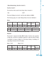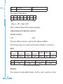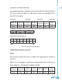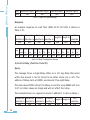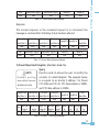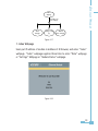
1
This manual may not be reproduced in whole or in part by any means, without
written permission of Accuenergy.
The information contained in this document is believed to be accurate at the
time of publication, however, Accuenergy assumes no responsibility for any
errors which may appear here and reserves the right to make changes without
notice. Please ask the local representative for latest product specifications
before ordering.
Ethernet Modual
Copyright © 2007 V1.0
Ethernet Modual
Please read this manual carefully before dong installation, operation and
maintenance of Acuvim II meter.
Following symbols are used in this user’s manual and on Acuvim II meter to
alert the dangerous or to prompt in the operating or set process.
Dangerous symbol, Failure to observe the information may result in
injury or death.
Alert symbol, Alert the potential dangerous. Observe the information
after the symbol to avoid possible injury or death.
Focus symbol, avoid inadvertent operations which may lead to
abnormal working of instrument, even damage to the instrument or
physical harm.
This mark is on product for UL Listed product
Installation and maintenance of the Acuvim II meter should only be performed
by qualified, competent personnel that have appropriate training and
experience with high voltage and current device.
This document is not fit for any untrained people. Accuenergy is not
responsible for any problem happens under proper operation.
II
III
Ethernet Modual
Chapter 1 Introduction------------------------------------------------------------------1
1.1 Ethernet Introduction---------------------------------------------------2
1.2 Function Description of Ethernet module-----------------------------2
Chapter 2 Wiring and Connection-----------------------------------------------------5
2.1 Appearance and Dimensions--------------------------------------------6
2.2 Installation Method------------------------------------------------------7
2.3 Definition of RJ45 Interface---------------------------------------------8
2.4 Cable-----------------------------------------------------------------------9
2.5 Connection Method------------------------------------------------------9
Chapter 3 Function Description of Ethernet MODULE----------------------------11
3.1 Initializing Ethernet Module-------------------------------------------12
3.2 Searching IP Address of Ethernet Module----------------------------22
3.3 Description of Modbus/TCP protocol---------------------------------24
3.4 Browse Webpage and Set Parameters--------------------------------32
3.5 Mail Function------------------------------------------------------------45
Appendix----------------------------------------------------------------------------------47
Appendix A Technical Data and Specifications---------------------------------------48
Appendix B Ordering Information------------------------------------------------------49
Appendix C Revision History------------------------------------------------------------50
Ethernet Modual
Starting!
Congratulations!
You have gotten an advanced, versatile, multifunction power meter. You can
call it Remote terminal unit (RTU), and it will benefit your power system.
This manual is about Ethernet module of Acuvim II meter. With Ethernet
module, Acuvim II meter can be linked to Ethernet network easily, and it can
realize distribution automation based on Ethernet.
Please read this manual carefully before operating and setting the Acuvim II
meter to avoid unnecessary trouble.
Chapter 1 helps you to understand the fundamental concept of Ethernet, and
application points of Ethernet module.
Chapter 2 describes in detail hardware features of Ethernet module.
Chapter 3 describes in detail function application of Ethernet module.
Appendix lists technical data and specifications and ordering information of
Ethernet module.
IV
Chapter 1 Introduction
Ethernet Introduction
Function Description
1
Ethernet Modual
Ethernet module is an extended communication module of Acuvim II
meter. With Ethernet module, Acuvim II meter can be linked to Ethernet
easily.
1.1 Ethernet Introduction
Ethernet was originally developed by Xerox and then developed further
by Xerox, DEC, and Intel. Ethernet uses a Carrier Sense Multiple Access
with Collision Detection (CSMA/CD) protocol, and provides transmission
speeds up to 10 Mbps.
Now Ethernet stands for LAN with CSMA/CD protocol.
Ethernet is not a material network, and it is the technology standard.
Ethernet is the most current communication standard in LAN. This
standard defines the used type of cable and the used method of Signal
processing in LAN.
1.2 Function Description of Ethernet module
Please read appendix of technical data and specifications of Ethernet
module before using it.
﹡The Ethernet module supports Modbus/TCP protocol. It is used as
server, and the default value of protocol port is 502, and the user defined
range of protocol port is 2000~5999. Device address is the same as
Acuvim II meter.
﹡The Ethernet module supports SMTP protocol. It has Mail Function and
supports “Send mail for timing” mode and “Send mail for event” mode.
Ethernet Modual
﹡The Ethernet module supports HTTP protocol. It is used as HTTP server,
and the default value of protocol port is 80, and the scope of protocol
port is 6000~9999.
Ethernet Modual
Chapter 2 Wiring and Connection
Appearance and Dimensions
Installation Method
Definition of RJ45 Interface
Cable
Connection Method
5
Ethernet Modual
NOTE
Ethernet module must be linked
to Acuvim II meter when it is to
be used. In addition, Ethernet
module must be the first extended
module linked to Acuvim II meter.
The environment temperature and
humidity should fulfill the requirement
of Acuvim II meter. Otherwise it may
cause the meter damage.
2.1 Appearance and Dimensions
22mm
(Side View)
90mm
55.6mm
(Top View)
Ethernet Modual
(Bottom View)
2.2 Installation Method
Ethernet module is linked to Acuvim II meter by communication plug. It
can also be linked to other extended modules like IO modules.
1. Insert the installation clips to the counterpart of Acuvim II meter,
and then press the Ethernet module lightly, so linking is established.
2.
Tighten the installation screw.
Ethernet Modual
Note:
1. lightly in installation or it may cause damage to the IO modules;
2. Installation with power is forbidden.
2.3 Definition of RJ45 Interface
The Ethernet module uses standard RJ45 connector access Ethernet
network. The mechanical and electrical characteristics of connector are
consistent with the requirements of IEC 603-7.
(Top View)
Script
1
2
3
4
5
ID
TX+
TXRX+
n/c
n/c
Content
Tranceive Data+
Tranceive DataReceive Data+
Not connected
Not connected
6
7
8
RXn/c
n/c
Receive DataNot connected
Not connected
LED_L (yellow): display speed status. LED on indicates 100Mbps, while
LED_R (green): display link and activity status combined. LED on
indicates link status, while LED flash indicates activity.
2.4 Cable
Shielded twisted-pair cable (standard 568A or standard 568B) is usually
recommended as reference to the EIA/TIA standard.
2.5 Connection Method
1. Direct Connect
Ethernet module use cross line (standard 568A) to connect to computes.
Users may refer to the third chapter “Function description of Ethernet
module” for using Ethernet module. Module supports Modbus/TCP and
HTTP functions for direct connect.
2. Indirect Connect
Ethernet module use straight line (standard 568B) access Ethernet
through router or hub. Users may refer to the third chapter “Function
description of Ethernet module” for using Ethernet module.
Ethernet Modual
LED off indicates 10Mbps.
10
Ethernet Modual
Chapter 3 Function Description
Initializing Ethernet Module
Searching IP Address of Ethernet Module
Description of Modbus/TCP protocol
Browse Webpage and Set Parameters
Mail Function
11
Ethernet Modual
Detail of Ethernet module will be described in this chapter. It includes
how to set parameters of module, how to get IP address and Mac
address of module, content about Modbus/TCP protocol, how to visit
webs, and how to use mail function.
3.1 Initializing Ethernet Module
AXM-Net default settings are
IP Address (192.168.1.254);
Subnet Mask (255.255.255.0);
Gateway (192.168.1.1);
Primary DNS Server (202.106.0.20).
If you don’t know the settings of module when power on for the fist time,
you may use the panel of Acuvim II to get them and to configure them.
This procedure shows how to configure Ethernet module settings by
panel:
a) Press “H” key and “V/A” key simultaneously on Acuvim II will go to the
menu selecting mode. Cursor “Meter” flashes in this mode.
12
Ethernet Modual
Figure 3-1
b) Press “P” key or “E” key, move cursor to “Setting”. Press “V/A” key,
go to the meter parameter setting mode. Device address page is the first
page of “Setting” mode. It shows the Modbus address of the device for
several seconds, and then the screen goes to Access Code page. Press “V/
A” key, go to the parameter setting page. Press “P” key or “E” key, move
cursor to “NET”, press “V/A” key, go to Ethernet module setting page.
Figure 3-2
13
Ethernet Modual
Figure 3-3
Figure 3-4
c) Set configuration mode in the first setting page. “AUTO” means that
users configure module settings with DHCP protocol while “MANU” means
that users configure module settings with manual setting. Press “V/A”
key, go to setting state, and the pointed area will flash. Press “P” key or
14
Note: If you select the “AUTO” mode, please go to step k) directly and
reset module. Wait until the reset is finished and find the new IP address
in the following step.
Figure 3-5
d) Set IP Address in the second setting page, such as 192.169.1.100
as shown below. Press “V/A” key, go to setting state. Users may set
parameter in the pointed area, and cursor starts at the first digit bit.
After setting IP Address completely, press “V/A” key to affirm. Again
press “P” key, go to the third setting page for Subnet Mask.
15
Ethernet Modual
“E” key to select configuration mode, press “V/A” key to affirm. Again
press “P” key, go to the second setting page for IP Address.
Ethernet Modual
Figure 3-6
e) Set Subnet Mask in the third setting page, such as 255.255.255.0.
Press “V/A” key, go to setting state. Users may set parameter in the
pointed area, and cursor starts at the first digit bit. After setting Subnet
Mask completely, press “V/A” key to affirm. Again press “P” key, go to
the fourth setting page for Gateway.
Figure 3-7
16
Figure 3-8
17
Ethernet Modual
f) Set Gateway in the fourth setting page, such as 192.169.1.1. Press “V/
A” key, go to setting state. Users may set parameter in the pointed area,
and cursor starts at the first digit bit. After setting Gateway completely,
press “V/A” key to affirm. Again press “P” key, get into the fifth setting
page for DNS Primary Server.
Ethernet Modual
g) Set DNS Primary Server in the fifth setting page, such as 202.106.0.20.
Press “V/A” key, go to setting state. Users may set parameters in the
pointed area, and cursor starts at the first digit bit. After setting DNS
Primary Server completely, press “V/A” key to affirm. Again press “P”
key, go to the sixth setting page for DNS Secondary Server.
Note: if you want to use SMTP function, DNS parameters must be set
correctly.
Figure 3-9
18
Note: if you want to use SMTP function, DNS parameters must be set
correctly.
Figure 3-10
19
Ethernet Modual
h) Set DNS Secondary Server in the sixth setting page, such as
202.106.196.115. Press “V/A” key, go to setting state. Users may set
parameter in the pointed area, and cursor starts at the first digit bit.
After setting DNS Secondary Server completely, press “V/A” key to affirm.
Again press “P” key, go to the seventh setting page for Modbus/TCP port.
Ethernet Modual
i) Set Modbus/TCP port in the seventh setting page, such as 502. Press
“V/A” key, go to setting state. Users may set parameter in the pointed
area, and cursor starts at the first digit bit. After setting Modbus/TCP
port completely, press “V/A” key to affirm. Again press “P” key, go to
the eighth setting page for HTTP port. Modbus/TCP port’s default value
is 502, and the user defined range of port is 2000~5999. If the set port is
not in the range, the set port will return default value.
Figure 3-11
20
Figure 3-12
k) Set resetting mode in the ninth setting page. Select “RESET” to reset
module. Select “NO” means not to reset module. Select “DEFAULT”
means load module with default settings and reset module. Press “V/A”
key, go to setting state, and the pointed area flashes. Press “P” key or “E”
key to select configuration mode, press “V/A” key to affirm.
Note: When configuring Ethernet module settings completely, users must
select “RESET” to restart module and new settings will take effect.
21
Ethernet Modual
j) Set HTTP port in the eighth setting page, such as 80. Press “V/A” key,
go to setting state. Users may set parameter in the pointed area, and
cursor starts at the first digit bit. After setting HTTP port completely,
press “V/A” key to affirm. Again press “P” key, go to the ninth setting
page for resetting mode. HTTP port’s default value is 80, and the user
defined range of port is 6000~9999. If the set port is not in range, the
set port will return default value.
Ethernet Modual
Figure 3-13
l) After configuring AXM-Net settings completely, press “H” key and “V/A”
key simultaneously to return menu selecting mode. Users can do other
operation.
3.2 Searching IP Address of Ethernet Module
Acuvim II tool software supports search function, and Users use it to get
IP address and MAC address of Ethernet module.
Operation step:
1) Press “Start” menu of tool software.
2) Press “Search Device” menu.
22
Ethernet Modual
Figure 3-14
3) Tool software pop-up “Search Device(s)” window, and window display
IP address and MAC address of module.
Figure 3-15
23
Ethernet Modual
3.3 Description of Modbus/TCP protocol
The Modbus/TCP protocol is used for communication in Ethernet module.
The protocol sets up master/slave link in Ethernet. First, master device
(client) sets up TCP link with slave device (server). Second, master
device sends request frame to slave device, and slave device receives
request frame and returns response frame to master device. Figure 3-16
displays working mode of Modbus/TCP protocol.
Request
Indication
Modbus Client
Modbus Server
Confirmation
Response
Figure 3-16
1. Protocol
1) Data Frame Format
MBAP Header
7x8-Bits
Function
8-Bits
Data
Nx8-Bits
Table 3-1
2) Modbus Application Header (MBAP Header) Field
Modbus application Header field is start of data frame, and it is consist of
seven bytes.
Field
Transaction
Identifier
Protocol Identifier
Length
Unit Identifier
Length
2 Bytes
2 Bytes
2 Bytes
1 Byte
Description
Identification of a Modbus Request/Response
transaction
Modbus protocol=0
Number of following bytes
Slave address, in the range of 0~247 decimal.
Table 3-2
24
The function code field of a message frame contains eight bits. Valid
codes are in the range of 1~255 decimal. When a message is sent from a
client to a server device the function code field tells the server what kind
of action to perform.
Code
Meaning
Action
01 Read Relay Output Status
Obtain current status of Relay Output
02 Read Digital Input(DI) Status Obtain current status of Digital Input
Obtain current binary value in one or more
03 Read Data
registers
05 Control Single Relay Output Force Relay to a state of on or off
Place specific value into a series of consecutive
16 Write Multiple-registers
multiple-registers
Table 3-3
4) Data Field
The data field is constructed using sets of two hexadecimal digits, in
the range of 00 to FF hexadecimal. The data field of messages sent
from a master to slave devices contains additional information which
the slave must use to take the action defined by the function code. This
can include items like discrete and register addresses, the quantity of
items to be handled, and the count of actual data bytes in the field.
For example, if the master requests a slave to read a group of holding
registers (function code 03), and the data field specifies the starting
register and how many registers are to be read. If the master writes to
a group of registers in the slave (function code 10 hexadecimal), the
data field specifies the starting register, how many registers to write, the
count of data bytes to follow in the data field, and the data to be written
into the registers.
25
Ethernet Modual
3) Function Field
Ethernet Modual
2. Format of communication
Explanation of frame
Transaction Transaction Protocol
Protocol
Unit
Length hi Length lo
identifier hi identifier lo identifier hi identifier lo
identifier
00H
00H
00H
00H
00H
06H
01H
Fun
03H
Data start reg hi
40H
Data start reg lo
00H
Data #of regs hi
00H
Data #of regs lo
48H
Table 3-4
As shown in table 3-4 the meaning of each abbreviated word is:
Transaction identifier hi: Transaction Identifier high byte
Transaction identifier lo: Transaction Identifier low byte
Protocol identifier hi: Protocol Identifier high byte
Protocol identifier lo: Protocol Identifier low byte
Length hi: length high byte
Length lo: length low byte
Unit identifier: slave address
Fun: function code
Data start reg hi: start register address high byte
Data start reg lo: start register address low byte
Data #of regs hi: number of register high byte
Data #of regs lo: number of register low byte
26
Ethernet Modual
1) Read Status Relay (Function Code 01)
Function Code 01
This function code is used to read relay status in Acuvim II.
1=On
0=Off
There are 8 Relays in Acuvim II, and the start address is 0000H.
The following query is to read 2 Relays Status of Acuvim II Address 1.
Query
Transaction Transaction
Protocol
Protocol
Unit
Length hi Length lo
identifier hi identifier lo identifier hi identifier lo
identifier
00H
00H
00H
00H
00H
06H
01H
Fun
01H
Data start reg hi
00H
Data start reg lo
00H
Data #of regs hi
00H
Data #of regs lo
02H
Table 3-5 Read 2 Relays Status Query Message
Response
The Acuvim II response includes MBAP Header, function code, quantity
of data byte, the data. An example response to read the status of Relay
1 and Relay 2 is shown as Table 3-6. The status of Relay 1 and Relay 2 is
responding to the last 2 bit of the data.
Relay 1: bit0
Relay 2: bit1
Transaction Transaction
Protocol
Protocol
Unit
Length hi Length lo
identifier hi identifier lo identifier hi identifier lo
identifier
00H
00H
00H
00H
00H
04H
01H
27
Ethernet Modual
Fun
01H
Byte count
01H
Data
02H
The content of the data is,
7
0
6
0
5
0
4
0
MSB
3
0
2
0
1
1
0
0
LSB
(Relay 1 = OFF , Relay 2=ON)
Table 3-6 Read 2 Relays Status Response Message
2) Read Status of DI (Function Code 02)
Function Code 02
1=On
0=Off
There are 38 DIs in Acuvim II, and the start address is 0000H.
The following query is to read the 4 DIs Status of address 1 of Acuvim II.
Query
Transaction Transaction
Protocol
Protocol
identifier hi identifier lo identifier hi identifier lo
00H
00H
00H
00H
Fun
02H
Data start reg hi
00H
Data start reg lo
00H
Length hi Length lo
00H
Data #of regs hi
00H
06H
Unit
identifier
01H
Data #of regs lo
04H
Table 3-7 Read 4 DIs Query Message
Response
The response includes MBAP Header, function code, quantity of data
28
An example response to read the status of 4 DIs (DI1=On, DI2=On, DI3=On,
DI4= On) is shown as Table 3-8. The status of each is responding to the
last 4 bit of the data.
DI1: bit0
DI2: bit1
DI3: bit2
DI4: bit3
Transaction Transaction Protocol
Protocol
Unit
Length hi Length lo
identifier hi identifier lo identifier hi identifier lo
identifier
00H
00H
00H
00H
00H
04H
01H
Fun
02H
Byte count
01H
Data
0FH
The content of the data is,
7
0
MSB
6
0
5
0
4
0
3
1
2
1
1
1
0
1
LSB
Table 3-8 Read 4 DIs Response Message
3) Read Data (Function Code 03)
Query
This function allows the users to obtain the measurement results of
Acuvim II.
Table 3-9 is an example to read the 6 measured data (Time) from server
device address 1, the data start address is 1040H.
Transaction Transaction Protocol
Protocol
Unit
Length hi Length lo
identifier hi identifier lo identifier hi identifier lo
identifier
00H
00H
00H
00H
00H
06H
01H
29
Ethernet Modual
characters, the data characters.
Ethernet Modual
Fun
03H
Data start reg hi
10H
Data start reg lo
40H
Data #of regs hi
00H
Data #of regs lo
06H
Table 3-9 Read Time Query Message
Response
An example response to read Time (2006-12-18 14:15:20) is shown as
Table 3-10.
Transaction Transaction Protocol
Protocol
Length hi Length lo
identifier hi identifier lo identifier hi identifier lo
00H
00H
00H
00H
00H
0FH
Unit
identifier
01H
Byte Data1 Data1 Data2 Data2 Data3 Data3 Data4 Data4 Data5 Data5 Data6 Data6
count hi
lo
hi
lo
hi
lo
hi
lo
hi
lo
hi
lo
03H 0CH 07H D6H 00H 0CH 00H 12H 00H 0EH 00H 0FH 00H 14H
Fun
Table 3-10 Read Time Response Message
4) Control Relay (Function Code 05)
Query
The message forces a single Relay either on or off. Any Relay that exists
within the Acuvim II can be forced to be either status (on or off). The
address of Relay starts at 0000H, and Acuvim II has eight Relay.
The data value FF00H will set the Relay on and the value 0000H will turn
it off; all other values are illegal and will not affect that relay.
The example below is a request to Acuvim II address 1 to turn on Relay 1.
Transaction Transaction Protocol
Protocol
Unit
Length hi Length lo
identifier hi identifier lo identifier hi identifier lo
identifier
00H
00H
00H
00H
00H
06H
01H
30
Data start reg hi
00H
Data start reg lo
00H
Value hi
FFH
Value lo
00H
Table 3-11 Control Relay Query Message
Response
The normal response to the command request is to retransmit the
message as received after the Relay status has been altered.
Transaction Transaction Protocol
Protocol
Unit
Length hi Length lo
identifier hi identifier lo identifier hi identifier lo
identifier
00H
00H
00H
00H
00H
06H
01H
Fun
05H
Data start reg hi
00H
Data start reg lo
00H
Value hi
FFH
Value lo
00H
Table 3-12 Control Relay Response Message
5) Preset/Reset Multi-Register (Function Code 16)
NOTE
Pr o h i b i t w r i t i n g
zone which have no
attribute of write
Query
Function code 16 allows the user to modify the
contents of a Multi-Register. The example below
is a request to an Acuvim II address 1 to Preset
CT1 (500) and CT2 (5). CT1 data address is 1008H,
and CT2 data address is 1009H.
Transaction Transaction
Protocol
Protocol
Unit
Length hi Length lo
identifier hi identifier lo identifier hi identifier lo
identifier
00H
00H
00H
00H
00H
0BH
01H
Data start Data start Data #of Data #of Byte Value1 Value1 Value2 Value2
reg hi
reg lo
regs hi regs lo count
hi
lo
hi
lo
10H
10H
08H
00H
02H
04H
01H
F4H
00H
05H
Fun
Table 3-13 Preset CT Value Query Message
31
Ethernet Modual
Fun
05H
Ethernet Modual
Response
The normal response to a preset Multi-Register request includes MBAP
Header, function code, data start register, the number of registers.
Protocol
Unit
Transaction Transaction Protocol
Length hi Length lo
identifier
identifier hi identifier lo identifier hi identifier lo
00H
00H
00H
00H
00H
06H
01H
Fun
10H
Data start reg hi Data start reg lo
10H
08H
Data #of regs hi
00H
Data #of regs lo
02H
Table 3-14 Preset Multi-Registers Response Message
Users may refer to the fifth chapter “Communication” and get the details
of Acuvim II.
When users use Moubus/Tcp function, you set best the Scan Interval of
tool soft under 1000ms, and set best the Frame Interval of the third soft
under 1000ms.
3.4 Browse Webpage and Set Parameters
Ethernet module supports HTTP protocol, has Web Sever function. Users
may visit Acuvim II through Ethernet whenever and wherever.
Ethernet module supports IE Browser 5.0 and above editions and Webpage
Settings only supports ASCII character.
We assume “192.169.1.200” as IP address of module.
Figure 3-17 is flow chart for entering webpage.
32
Ethernet Modual
“Index”
Webpage
Press link to get
into webpage
“Data”
Webpage
“Settings”Webp
age
“Module
Status”Webpage
Figure 3-17
1. Index Webpage
Users put IP address of module in Address of IE Browser, and enter “Index”
webpage. “Index” webpage supplies three links to enter “Data” webpage
or “Settings” Webpage or “Module Status” webpage.
Figure 3-18
33
Ethernet Modual
2. Module Status Webpage
Press “Module Status” link to enter module status webpage. Webpage
shows the state of module and the settings of module.
Figure 3-19
3. Settings Webpage
Press “Settings” link to enter settings webpage. Figure 3-20 is flow chart
for settings webpage. First IE Browser enters “Password” webpage, and
it need check module password. Initial password is 12345678. There are
five kinds of setting webpages. They are “Network Settings” webpage,
“Mail Settings” webpage, “Webpage Settings” webpage, “Load Default”
webpage, and “Password Setting” webpage.
34
Press link to
enter settings
webpage
“Settings”
Webpage
Password
check
Select Network Setting
Mode, and Press Affirm
Button
Set Mail Settings ,
Select Mail Mode ,
and Press Affirm
Button
“Mail
Settings”
Webpage
“Webpage
Settings”
Webpage
“Load
Default”
Webpage
“Password
Setting”
Webpage
Timing
Mode
Event
Mode
None
Mode
Set Webpage
Settings, and Press
Affirm Button
Select “Load
Default” Manner,
and Press Affirm
Button
Set New Password,
and Press Affirm
Button
Ethernet Modual
“Network
Settings”
Webpage
Complete
Webpage
“Timing
Content”
Webpage
“Event
Content”
Webpage
Complete
Webpage
Select
Content, and
Press Affirm
Button
Select
Content, and
Press Affirm
Button
Complete
Webpage
Complete
Webpage
Complete
Webpage
Complete
Webpage
Complete
Webpage
Figure 3-20
35
Ethernet Modual
1) “Password” Webpage
Figure 3-21: “Password” webpage. If the password is valid, IE Browser
will enter “Network Settings” webpage, or else IE Browser will return to
“Password” webpage.
Figure 3-21
2) “Network Settings” Webpage
Figure 3-22: “Network Settings” webpage. It supports two network
setting mode: Manual or Auto. Except network setting mode, there are
two port settings in Webpage. One is HTTP port, and the other is Modbus/
TCP port. The default value of Modbus/TCP port is 502, and the user
defined range is 2000~5999. The default value of HTTP port is 80, and the
user defined range is 6000~9999.
After new network settings go into effect, users may enter webpage
according to new IP address.
36
Ethernet Modual
Figure 3-22
Figure 3-23: Configure network settings completely for Manual mode
webpage.
Figure 3-23
Figure 3-24: configure network settings completely for Auto mode
webpage.
37
Ethernet Modual
Figure 3-24
3) “Mail Settings” Webpage
Figure 3-25: “Mail Settings” webpage. Users should not set “Mail From”
the same as “Mail to”. Because some SMTP servers may reject the
connection for these settings and the module may not send mail. The
value of “Mail Sending Interval” is interval time between two mails under
“Send mail for timing” mode, the default value is 1 hour, the range is
1~168 hours. The “Select mode of mail” mode includes “Send mail for
timing” mode, “Send mail for event” mode, “None” mode. Users could
select single mode and the default mode is “None” mode.
38
Ethernet Modual
Figure 3-25
Figure 3-26: select mail content for “Send mail for timing” mode
webpage. “Send mail for timing” mode is a timing manner according to
“Mail Sending Interval” which sends mail content to “Mail to” mail box.
Under this mode, mail content includes “Real-Time Metering”, “Energy
and Harmonics”, “Max and Min”, and users may select either or all of them.
Figure 3-26
39
Ethernet Modual
Figure 3-27: select mail content for “Send mail for event” mode
webpage. “Send mail for event” mode is a manner of event triggered
according to event type (“Alarm” type, “SOE” type) which sends mail
content to “Mail to” mail box. Under this mode, mail content includes
“Alarm Event”, “SOE Event”, and users may select either or all of them.
Figure 3-27
Figure 3-28: set “None” mode completely webpage. Mail function is
unable.
Figure 3-28
40
Ethernet Modual
Figure 3-29: configure Mail Settings completely webpage.
Figure 3-29
The value of “Mail From” and “Mail To” and “Mail Subject” and “Mail
Sending Interval” needn’t be set repeatedly.
4) “Webpage Settings” Webpage
Figure 3-30: “Webpage Settings” webpage. Users set the value of “Device’
s Description” according to meter type. The default value of “Data Page
Refresh Interval” is 5S, and the range is 5~30S. The select of “Language”
supports English and Simplified Chinese.
41
Ethernet Modual
Figure 3-30
Figure 3-31: webpage settings set completely webpage.
Figure 3-31
5) “Load Default” Webpage
Figure 3-32: “Load Default” webpage.
Figure 3-32
42
Figure 3-33
6) “Password Setting” Webpage
Figure 3-34: “Password Setting” webpage.
Figure 3-34
43
Ethernet Modual
Figure 3-33: Load default successful webpage. The network settings of
module will renewed default value.
Ethernet Modual
Figure 3-35: set password successful webpage.
Figure 3-35
4. Data Webpage
Press “Data” Link to Visit Data webpage. Figure 3-36 is flow chart of data
webpage. There are six kinds of data webpage. They are “Metering”
webpage, “Energy and Harmonics” webpage, and “Max and Min #1”,
“Max and Min #2” webpage, “Alarm Record” webpage, and “SOE Record”
“Metering ”
“Energy and
Harmonics”
Press link to
get into these
webpage
“Max and Min #1”
Data Webpage
“Max and Min #2”
“Alarm Record”
“SOE Record ”
44
Figure 3-36
“Metering” webpage includes the data of real-time parameters for
Acuvim II. There are thirty six parameters, such as Volts AN, I A, Watt A.
“Energy and Harmonics” webpage includes the data of energy and
harmonics parameters for Acuvim II. There are seventeen parameters,
such as Delivered kWh, kVAh, and THD Volts Average.
“Max and Min #1” webpage includes the max and min data of parameters
for Acuvim II. There are thirteen parameters, such as Volts AN, I A , and
Watt Total(Demand).
“Max and Min #2” webpage includes the max and min data of parameters
for Acuvim II. There are twelve parameters, such as Frequency, Imbalance
V, and THD I A.
“Alarm Record” webpage includes alarm records for Acuvim II. There
are sixteen groups record. Each record includes Time Stamp, Limit ID,
Status, Alarm Channel and Value.
“SOE Record” webpage includes SOE record for Acuvim II. There are
twenty groups record. Each record includes Time Stamp, DI Status.
3.5 Mail Function
Because Ethernet module supports SMTP protocol, it has mail function.
Before sending mail, users must set the parameters of DNS Server. Users
may refer to the fourth section “Browse Webs and Set Parameters” and
set the parameters of DNS Server.
45
Ethernet Modual
webpage. Each webpage may refresh according to “Data Page Refresh
Interval” and show work status of Acuvim II then.
Ethernet Modual
There are two mail modes according as function. One is “Send mail for
timing” mode; the other is “Send mail for event” mode. “Send mail for
timing” mode is a timing manner according to “Mail Sending Interval”
which sends mail content to “Mail to” mail box. The mail content
includes “Real-Time Metering”, “Energy and Harmonics”, “Max and Min”.
“Send mail for event” mode is a manner of event triggered according to
event type (“Alarm” type, “SOE” type) which sends mail content to “Mail
to” mail box and remind users. The mail content includes “Alarm Event”,
“SOE Event”.
Set mail settings completely, module will start work according to set
mode.
46
Appendix
Appendix A Technical Data and Specifications
Appendix B Ordering Information
Appendix C Revision History
47
Ethernet Modual
Appendix 1 Technical data and specification
Standards
Environmental
Safety
MODBUS Messaging Implementation Guide V1.0a
RFC793
RFC821
RFC2616
IEC 60068-2-30
IEC 61010-1
Communication Port
Physical Layer
Protocol
Baud Rate
Standard RJ45 socket
Modbus/TCP, SMTP, HTTP
10M/100M auto-adapted
Suitable Condition
Dimensions
Weight
Operating Temperature
Storage Temperature
Humidity
Power Supply
Power Consumption
90X55.6X22 (mm)
65g
-25ºC~70ºC
-40ºC~85ºC
5%~95% non-condensing
DC 5V (supplied by Acuvim II meter)
1W
Protocol Standards
48
Ethernet Modual
Appendix 2 Ordering Information
Type: AXM-NET
49
Ethernet Modual
Appendix C Revision History
Revision
1.0
50
Date
20070915
Description