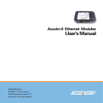
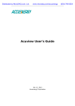
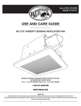
1
AN
SOLUTION
V: 1.0 Revised: 9-9-2015
ACUMESH - WIRELESS METERING
SYSTEM
SAFETY INFORMATION
COPYRIGHT © 2015 V1.0
Please read this manual carefully before installation,
This manual may not be altered or reproduced in whole
or in part by any means without the expressed written
consent of Accuenergy.
The information contained in this document is believed
to be accurate at the time of publication, however,
Accuenergy assumes no responsibility for any errors which
operation and maintenance of Acuvim II series meter.
The following symbols in this manual and on Acuvim II
series meters are used to provide warning of danger or risk
during the installation and operation of the meters.
Electric Shock Symbol: Carries information about
procedures which must be followed to reduce the
risk of electric shock and danger to personal health.
may appear here and reserves the right to make changes
Safety Alert Symbol: Carries information about
without notice. Please ask the local representative for latest
circumstances which if not considered may result in
product specifications before ordering.
injury or death.
This mark indicates that this product is UL listed.
[Document #0000A0000 Revision Date: Oct., 2015]
Installation and maintenance of the AcuMesh wireless
metering system should only be performed by qualified,
competent professionals who have received training and
should have experience with high voltage and current
devices.
Accuenergy shall not be responsible or liable for any
damages caused by improper meter installation and/or
operation.
Pg: 1
V: 1.0 Revised: 9-9-2015
CONTENTS
Chapter 1: Introduction3
1.1 AcuMesh Overview
3
1.3 Communication
3
1.4 Applications
4
1.5 Hardware Overview
4
1.6 Key Specifications
5
Chapter 2: Hardware Installation
6
2.1 Installation Checklist
6
2.2 Standalone Transceiver: Power
7
2.3 Standalone Transceiver: LEDs
7
2.4 Standalone Transceiver: Power Connection
8
2.5 AXM-Mesh: Attaching to Acuvim II
9
2.6 AXM-Mesh: Configuring with Devices
9
Chapter 3: Advanced User Settings
10
3.1 AcuMesh Software Introduction
10
3.2 Locating a Transceiver
11
3.3 Radio Configuration
12
3.4 Security Settings
13
3.5 Transceiver Information
14
3.6 Stand-Alone Transceiver Configuration
15
3.7 Serial Interfacing
16
Pg: 2
V: 1.0 Revised: 9-9-2015
ACUMESH OVERVIEW
The AcuMesh wireless RS485 network solution is
designed to connect energy meters and any devices by
communicating with RS485 wirelessly. AcuMesh is a costeffective solution that eliminates the need for installation
of communication wires. Saving premium time, labour, and
reducing the challenges of retrofit applications.
LONGER, RELIABLE
COMMUNICATION
The AcuMesh wireless system makes use of the Mesh
network structure which allows each transceiver to act
as extension points in the network allowing for larger
range of communication. Using this Mesh arrangement
for communication allows for point to multi-point
communication. This solution enables automatic selfhealing to optimize the communication pathway for a
more reliable communication.
Pg: 3
V: 1.0 Revised: 9-9-2015
APPLICATIONS
The AcuMesh wireless transceiver can be deployed in
following applications:
••
Power and Energy Metering in Commercial buildings,
Malls
••
Submetering and Tenant Billing for Entire Apartment,
Condominiums
••
Education Facilities and Campus
••
Industrial and Factory Facilities
••
Renewable Energy Generation such as Solar PV, Wind
and etc
••
Any network with device using RS485 communication
with any protocols
HARDWARE OVERVIEW
AcuMesh is available as two types of transcievers, these two types of transceivers
have no functional difference.
Standalone transceiver that can
AXM-Mesh transceiver module that
connect to any device via RS485 or PC
can only be attached to the Acuvim II
and gateways.
series meters.
Pg: 4
V: 1.0 Revised: 9-9-2015
KEY SPECIFICATIONS
Connection
Transceiver
AXM-Mesh Module
RS485 Screw terminal, USB mini-B (power supply or
configuration)
Attached to Acuvim II Power Meter
Data Rate
9600 bps
RF Properties
Operating Frequency Band
902 to 928 Mhz (900 Mhz ISM Band)
Spread Spectrum
Frequency Hopping
Number of Channels
64
Transmit Power Output
24 dBm (250 MW)
Receiver Sensitivity
-101 dBm
Indoor/Urban Range
Outdoor RF Line-of-Sight Range
Up to 1000’ (305 m)
Up to 4 miles (6.5 km) with 2.1 dB dipole antennas
RF Data Rate
Up to 200 kb/s
Antenna
Impedance
50 ohms unbalanced
Networking and Security
Supported Network Topologies
Addressing Options
Mesh, point-to-point, point-to-multipoint, peer-to-peer
Personal Area Network Identifier (PAN ID) and 64-bit MAC add addresses
Encryption
Power Requirements
128 bit Encryption Standard (AES)
Power supply included
Directly powered by meter
100-240Vac 47-63Hz
NA
Receive Current
60 mA (@9V)
NA
Transmit Current
140 mA (@9V)
NA
Power Supply
Physical Properties
Size
Weight
Operating Temperature
4.5 x 2.75 x 1.125 in. (11.4 x 7.0 x 2.9 cm)
NA
150g
NA
-40 to 85ºC (Industrial)
Pg: 5
V: 1.0 Revised: 9-9-2015
INSTALLATION CHECKLIST
You’ll need to confirm these details before successfully
completeing the installation of your AcuMesh system:
AcuMesh wireless system requires a
minimum of two transceivers to form the
network.
The RS485 network master device can be a
PC, PLC, data acquisition server or gateway,
e.g. AcuLink 710 Data Acquisition Server.
The slave devices can be our Acuvim II
series power meters or any other meter or
sensor with RS485 port. If it is the Acuvim II
meter, the AXM-Mesh transceiver module
should be used, for other devices the
standalone transceiver should be used.
Pg: 6
V: 1.0 Revised: 9-9-2015
HARDWARE INSTALLATION
Two types of Transceivers and two antenna choices.
STANDALONE TRANSCEIVER
POWER
The transceiver can easily be powered by connected it to the USB port of a
computer.
The AcuMesh transceiver can also be powered using a standard power supply of
100-240Vac or from an auxiliary wall socket to be powered.
Note: When the transceiver is connected to a gateway, PLC or power meter
through the RS485 port then the transceiver must be powered using the
external power supply.
The AXM-MESH module is directly powered by the Acuvim II series meter that it
is connected to.
LEDs
There are two sets of LED lights on the transceiver that indicate the transceivers
behaviour. The RSSI LED’s indicate the signal strength of the incoming signal.
3 LEDs ON - Very Strong Signal
2 LEDs ON - Strong Signal
1 LED ON - Moderate Signal
0 LED ON - Weak Signal
The Power LED’s indicates the activity of the transceiver.
The yellow LED indicates the transceiver is transmitting data.
The green LED indicates the transceiver is receiving data, the red LED indicates
the transceiver is powered on or it is communicating (the red light is on when
powered, off briefly during RF transmission).
Pg: 7
V: 1.0 Revised: 9-9-2015
STANDALONE TRANSCEIVER
Pin 1
TX/RX+
Pin 2
TX/RX-
Pin 5
GND
Pin
RS485
Description
1
TX/RX+
Positive Transmission Line
2
TX/RX-
Negative Transmission Line
5
GND
Ground
POWER CONNECTION
Connection for the 7-30Vdc power adapter.
DIP Switch
Switch 1 should always be in the ‘off’ position for half-duplex
communication.
Switch 2 is for full-duplex communication. This switch should not be
configured as most devices only support half-duplex communication.
RESET BUTTON
The reset button is used to reboot the transceiver. It is equivalent of power
cycle the transceiver.
Pg: 8
V: 1.0 Revised: 9-9-2015
AXM-MESH MODULE
ATTACHING TO A METER - ACUVIM II CONFIGURATION:
With the AXM-Mesh module attached to the meter, the meter should be
configured with the following settings to communicate:
Protocol 2: Mesh
NOTE: By changing the ‘Protocol 2’ setting to Mesh in the meter this will
automatically change the Baud rate 2 setting in the meter to 9600 and Parity 2
to None1
If the meter does not have Mesh option in Protocol 2, please set Baud rate 2 and
Parity 2 to 9600 and None1 respectively.
CONFIGURATION WITH OTHER DEVICES:
For other meters or devices that communicate through a RS485 port, the devices
must have the following settings to communicate with the transceiver:
Baud rate: 9600
Parity: None1 (Or Parity None, stop bit 1)
NOTES:
The Acuvim II meters and any other RS485 connected devices in the network
should be assigned with a unique Modbus address from 1-247.
The standalone transceiver can only be connected either via USB or via RS485 at
any time.
Pg: 9
V: 1.0 Revised: 9-9-2015
CONGRATULATIONS!
The AcuMesh RS485 wireless network set up is complete. You are now able to
communicate wirelessly with all RS45 devices in the network. The AcuMesh
wireless RS485 network is pre-configured to work out of box. No software
configuration is required.
CAUTION:
Proceed with caution to advance user setting below, you will not need to use the
AcuMesh software to have the AcuMesh Wireless RS485 network working, only
use the software if you have knowledge of wireless network properties. ADVANCED USER SETTINGS
Two types of Transceivers and two antenna choices.
By default, all the transceivers are configured in the same network. The
transceivers will be configured with the default network ID of 7FFF.
For advanced configurations such as configuring transceivers to work in a
different network, our “AcuMesh” software needs to be used.
NOTES:
A transceiver must be connected to a PC to perform any network configuration.
1. OPEN SOFTWARE:
Open the “AcuMesh” software. The following screen will appear.
Pg: 10
V: 1.0 Revised: 9-9-2015
2. LOCATE TRANSCEIVER:
To begin, the software will need to locate the transceiver that is connected to
the computer’s USB port. Click on the
to discover the Com port that the
transceiver is connected to. Select the Com port and click on ‘Finish’.
Click on the discovered transceiver to view and configure the settings related to
this transceiver.
Pg: 11
V: 1.0 Revised: 9-9-2015
3. RADIO CONFIGURATION:
The right side of the window will display the information and settings related to
the transceiver under the Radio Configuration view.
NOTE: To configure a remote transceiver in the network, the transceiver needs to
be in “remote control mode” (More information can be found below)
Pg: 12
V: 1.0 Revised: 9-9-2015
4. SECURITY SETTINGS:
To write a setting to the transceiver press on the
beside the parameter if it is
a read and write parameter.
To read or retrieve a parameter from the transceiver press the
beside the
parameter.
ID Network ID: The network or channel that the transceivers will communicate
in. All transceivers need to be configured with the same Network ID to
communicate with each other. Transceivers with different Network ID will not be
able to join the wireless network.
EE Encryption Enable: This parameter is for enabling an encryption for the
transceiver in the network.
KY AES Encryption Key: If the EE Encryption Enable parameter is enabled
then an Encryption key needs to be enter. This key must be set between 0-32
characters in Hexadecimal. Every transceiver must have the Encryption Key
correctly configured to join the network.
Pg: 13
V: 1.0 Revised: 9-9-2015
Note: More information can be found on each setting by clicking on the
symbol besides each parameter.
TRANSCEIVER INFORMATION:
NI Transceiver Identifier: This parameter is for assigning the transceiver with
a name so it can be easily identified in the network when searching for
transceivers. By default, no identifier is assigned to the transceivers.
SH Serial Number High: A read only parameter for returning the upper 32 bits of
the 64 bit unique assigned address to the transceiver.
SL Serial Number Low: A read only parameter for returning the lower 32 bits of
the 64 bit unique assigned address to the transceiver.
Pg: 14
V: 1.0 Revised: 9-9-2015
STAND-ALONE TRANSCEIVER CONFIGURATION:
AP Mode Options: For the transceiver to communicate with other transceivers in
the network this parameter must be set in ‘AT-Communication Mode [0].
To configure an individual transceiver, this parameter must be set to AP1Remote Control Mode[1].
D7 RS485 Configuration: If the transceiver is connected via a RS485 port then
this parameter must be set to ‘RS485 Enable High.’
Pg: 15
V: 1.0 Revised: 9-9-2015
SERIAL INTERFACING:
BD Baud Rate: The baud rate for serial communication between the serial port of
the module and the host. Default setting is 9600.
NB Parity: Parity for the serial communication. Default is None 1.
SB Stop Bits: Number of stop bits used in the serial communication. Default is
one stop bit.
To discover other transceivers within the network press the
besides the
transceiver that is connected to the computer’s USB port under the ‘Radio
Modules’ menu.
Pg: 16
V: 1.0 Revised: 9-9-2015
All the remote devices that are in the same network as this transceiver that are
found will appear in the pop up box. Press ‘Add Selected Devices’.
Once added, these remote devices will appear under the local standalone
transceiver and will be denoted as remote modules.
NOTE: By default these remote modules will be identified by their MAC Address.
Pg: 17
V: 1.0 Revised: 9-9-2015
To configure the settings for the remote modules, select the remote module
you wish to configure and its information will load under the radio configuration
view,
NOTE: The settings for the remote modules are identical to that of the local
transceiver.
Pg: 18
V: 1.0 Revised: 9-9-2015
NOTE: If you change the Network ID setting of a remote module, it will lose
connection and will be lost immediately. In such case, the network setting in
the local transceiver needs to be modified with this Network ID so that the local
and remote modules can communicate.
To configure a remote module from default settings:
••
Modify the network ID in the remote transceiver
••
Modify the network ID in the local transceiver after connection between the
remote transceiver has been lost in the preceding step.Industrial and Factory
Facilities
••
Discover remote transceiver again
Pg: 19
V: 1.0 Revised: 9-9-2015
TF: 1-877-721-8908
INT: +1-416-497-4100
FAX: +1-416-497-4130
E: [email protected]
ACCUENERGY (CANADA) INC.
2 Lansing Square, Suite 1001
Toronto, ON M2J 4P8, Canada