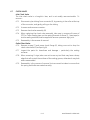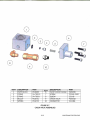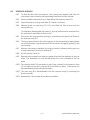
1
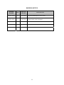
GE Sensing
Houston Center
User’s Manual Printing & Assembly Instructions
PRINTING:
1. FRONT & BACK COVER PAGES:
Front and Back cover pages (first and last pages) will be printed in color, single-sided on
8-1/2” x 11”, 65 lbs white paper.
2. INTRODUCTION PAGES:
Introduction section pages (up to Section 1.0) will be printed in color, single-sided on 81/2” x 11”, 24 lbs white paper.
3. SECTION & APPENDIX PAGES:
All Sections and Appendix pages will be printed in color, double-sided on 8-1/2” x 11”, 24
lbs white paper.
ASSEMBLY:
User’s Manual will be assembled with front and back 8-3/4” x 11-1/4” Clear View Plastic
Covers, bound with black spines of appropriate size.
PACKAGING:
The assembled User’s Manual will be packed in a clear plastic bag, or Saran-wrapped. The
package is labeled with bar-coded part number as per purchase order.
(This page not to be printed.)
1
GE Sensing
Models covered: Pressurements
Oil Operated Instruments: P3111; P3112; P3113; P3114; P3115; P3116
P3123; P3124; P3125
Distilled Water Operated Instruments: P3211; P3213; P3214; P3223; P3224
Hydraulic Deadweight Tester
User’s Manual
imagination at work
HYDRAULIC DEADWEIGHT TESTER
PRESSUREMENTS MODELS:
P3100 & P3200 SERIES
USER’S MANUAL
GE SENSING
10311 WESTPARK DRIVE
HOUSTON, TEXAS 77042
(713) 975 0547 FAX: (713) 975 6338
Release: 3100P-1D01
Revision: B
Date: 09/27/06
WARRANTY
GE Sensing warrants its products to conform to or exceed the specifications as set forth in its
catalogs in use at the time of sale and reserves the right, at its own discretion, without notice
and without making similar changes in articles previously manufactured, to make changes
in materials, designs, finish, or specifications.
GE Sensing warrants products of its own factory against defects of material or workmanship
for a period of one year from date of shipment.
Liability of GE Sensing under this warranty shall be limited to replacing, free of charge (FOB
Houston, Texas), any such parts proving defective within the period of this warranty, but will
not be responsible for transportation charges or consequential damages.
The warranty is not made for products manufactured by others which are illustrated and
described in GE Sensing catalogs or incorporated in GE Sensing products in essentially the
same form as supplied by the original manufacturer.
However, GE Sensing agrees to use its best efforts to have original suppliers make good their
warranties.
COPYRIGHT NOTICE
Copyright © 2006 by GE Sensing. All rights reserved. This document may not be reproduced
in part or in whole without the express written consent of GE Sensing.
DISCLAIMER
No representations or warranties are made with respect to the contents of this user’s
manual. Further, GE Sensing reserves the right to revise this manual and to make changes
from time to time in the content hereof without obligation to notify any person of such
revision.
TRADEMARK NOTICE
is a registered trademark of General Electric Corporation.
Trademarks or trade names are subject to state and federal laws concerning their
unauthorized use or other infringements. The fact that the product marks or names in this
manual do not bear a trademark symbol DOES NOT mean that the product name of mark is
not registered as a trademark or trade name. Any queries concerning the ownership or
existence of any trademarks or trade names mentioned in this manual should be
independently confirmed with the manufacturer or distributor of the product.
ii
REVISION NOTICE
RELEASE
NUMBER
REV.
DATE OF
RELEASE
3100P-1D01
A
05/31/06
Original release per DC/RO 25047
3100P-1D01
B
09/27/06
Pump check valve changed.
DESCRIPTION
iii
SAFETY SUMMARY
The following are general safety precautions that are not related to any specific procedures
and do not appear elsewhere in this publication. These are recommended precautions that
personnel must understand and apply during equipment operation and maintenance to
ensure safety and health and protection of property.
COMPRESSED LIQUID
Use of compressed liquids can create an environment of propelled foreign matter. Pressure
system safety precautions apply to all ranges of pressure. Care must be taken during testing
to ensure that all hydraulic connections are properly and tightly made prior to applying
pressure. Personnel must wear eye protection to prevent injury.
HEAVY WEIGHTS
Lifting and movement of heavy weights can create an environment of strain and impact
hazards. Care must be taken during testing to ensure that weight masses are lifted in a
manner that avoids over-reaching or twisting, and that the masses are not dropped.
Personnel must wear reinforced safety shoes to prevent injury.
PERSONAL PROTECTIVE EQUIPMENT
Wear eye protection and reinforced safety shoes approved for the materials and tools being
used.
iv
TABLE OF CONTENTS
WARRANTY .................................................................................................................................................................... ii
COPYRIGHT NOTICE .................................................................................................................................................. ii
DISCLAIMER ................................................................................................................................................................... ii
TRADEMARK NOTICE ................................................................................................................................................ ii
REVISION NOTICE ...................................................................................................................................................... iii
SAFETY SUMMARY ..................................................................................................................................................... iv
COMPRESSED LIQUID .............................................................................................................................................. iv
HEAVY WEIGHTS ........................................................................................................................................................ iv
PERSONAL PROTECTIVE EQUIPMENT .............................................................................................................. iv
TABLE OF CONTENTS ................................................................................................................................................. v
LIST OF FIGURES ........................................................................................................................................................ vii
1.0
GENERAL INFORMATION ....................................................................................................................
1.1
OPERATING PRINCIPLE ...........................................................................................................
1.2
ENVIRONMENTAL CORRECTIONS .......................................................................................
1.2.1 GRAVITY ..........................................................................................................................
1.2.2 TEMPERATURE .............................................................................................................
1.2.3 HEAD OF FLUID ...........................................................................................................
1.3
MODEL VARIATIONS .................................................................................................................
2.0
PREPARATION ........................................................................................................................................... 2-1
2.1
OPERATING FLUID ..................................................................................................................... 2-1
2.2
CONNECTIONS ........................................................................................................................... 2-1
3.0
PRIMING ...................................................................................................................................................... 3-1
4.0
OPERATION ................................................................................................................................................ 4-1
5.0
CALIBRATION IN DIFFERENT PRESSURE UNITS ....................................................................... 5-1
5.1
CONVERSION WEIGHTS .......................................................................................................... 5-1
5.2
SOFTWARE ................................................................................................................................... 5-1
6.0
MAINTENANCE & SERVICING ............................................................................................................ 6-1
6.1
PCU ASSEMBLY (10 mm NOMINAL DIAMETER) ............................................................. 6-1
6.2
PCU ASSEMBLY (2 & 3 mm NOMINAL DIAMETERS) ..................................................... 6-4
6.3
PCU ASSEMBLY (5 mm NOMINAL DIAMETER) ............................................................... 6-7
6.4
TOP PLATE REMOVAL ............................................................................................................. 6-10
6.5
SCREW PUMP ASSEMBLY ..................................................................................................... 6-11
6.6
PRIMING PUMP ASSEMBLY .................................................................................................. 6-13
6.7
CHECK VALVES ......................................................................................................................... 6-15
6.8
RESERVOIR ASSEMBLY .......................................................................................................... 6-17
v
1-1
1-1
1-3
1-3
1-3
1-4
1-4
7.0
FAULT FINDING ........................................................................................................................................
7.1
POOR PCU SPIN/SENSITIVITY ...............................................................................................
7.2
HIGH PCU FALL RATE ...............................................................................................................
7.3
SYSTEM WILL NOT PRIME ......................................................................................................
7.4
SYSTEM WILL NOT PRESSURIZE ..........................................................................................
7.5
PRIMING PUMP MALFUNCTION ..........................................................................................
7.6
CANNOT REACH MAXIMUM PRESSURE ...........................................................................
8.0
STORAGE & TRANSPORTATION ....................................................................................................... 8-1
8.1
INSTRUMENT ............................................................................................................................... 8-1
8.2
WEIGHTS ....................................................................................................................................... 8-1
9.0
ANCILLARY EQUIPMENT ......................................................................................................................
9.1
LIQUID-TO-LIQUID SEPERATOR, Model 5521 ................................................................
9.2
ANGLE ADAPTER, Model 5543 .............................................................................................
9.3
POINTER REMOVER/PUNCH, Model 5551 .......................................................................
vi
7-1
7-1
7-2
7-2
7-2
7-3
7-3
9-1
9-1
9-1
9-2
LIST OF FIGURES
Figure 1-1
Figure 1-2
Figure 1-3
Figure 1-4
Hydraulic Circuit Schematic................................................................................................... 1-2
Dual PCU Instrument................................................................................................................. 1-4
Single High Pressure PCU Instrument ............................................................................... 1-5
Single Low Pressure PCU Instrument ................................................................................ 1-5
Figure 2-2A
Figure 2-2B
Figure 2-2C
Making pressure Connections .............................................................................................. 2-2
Making Pressure Connections .............................................................................................. 2-3
Test Port Insert............................................................................................................................. 2-4
Figure 4-1
Figure 4-2
Float Height Indicator Post..................................................................................................... 4-1
Weight Rotation .......................................................................................................................... 4-2
Figure 6-1
Figure 6-2
Figure 6-3
Figure 6-5
Figure 6-6
Figure 6-7
Figure 6-8
10mm PCU Assembly................................................................................................................ 6-3
2 & 3 mm PCU Assembly ......................................................................................................... 6-6
5 mm PCU Assembly ................................................................................................................. 6-9
Screw Pump Assembly...........................................................................................................6-12
Priming Pump Assembly........................................................................................................6-14
Check Valve Assemblies ........................................................................................................6-16
Reservoir Assembly..................................................................................................................6-18
vii
SECTION 1.0
GENERAL INFORMATION
1.1
OPERATING PRINCIPLE
Deadweight Testers are the primary standard for pressure measurement. Utilizing the wellproven Piston-Gauge system, consisting of a vertically mounted, precision lapped Piston and
Cylinder assembly, accurately calibrated weight masses (Force) are loaded on the piston
(Area), which rises freely within its cylinder. These weights balance the upward force created
by the pressure within the system.
FORCE
PRESSURE =
AREA
Each weight is marked with the tester serial number, and the pressure measured when
placed on a correctly spinning and floating piston. The total pressure measured is the
summation of the weights plus the piston weight carrier assembly.
The schematic diagram below shows the basic hydraulic circuit for a dual-PCU (Piston
Cylinder Unit) instrument.
The system is primed with liquid from the Reservoir, and the system pressure is increased by
means of the Screw Pump. As liquids are considered incompressible, the displaced liquid
causes the pistons to rise within their cylinders to balance the downward force of the
weights.
Fluids at the same height in a system are at the same pressure, so when the system is in
equilibrium (i.e. the piston and weights are floating freely, rotating and falling at it’s natural
sink-rate), the pressure generated by the combined mass of the piston and weights equals
the pressure within the device under test.
The design of a Piston/Cylinder Unit (PCU) fitted to a deadweight tester allows for a very
small clearance gap between the piston and cylinder. This is required to allow the working
fluid to pass between the components, providing a lubricating film, and preventing metal-tometal contact.
Therefore, during the normal operation of a deadweight tester, the working fluid in the
system will slowly pass through this clearance gap. This is perfectly normal, and there are
Sump Rings around the piston bodies to collect the excess fluid.
Although calibration is carried out using one PCU at a time, there is a point during normal
operation of a dual-PCU instrument where both PCU’s will rise. This is due to the overlap in
pressure range of the two PCU’s. The PCU that is not in use will seal in the fully extended
position to avoid additional fluid loss.
1-1
INTRODUCTION
HIGH
PRESSURE
PCU
DEVICE
UNDER
TEST
LOW
PRESSURE
PCU
RESERVOIR
SCREW PUMP
PRIMING PUMP
FIGURE 1-1
HYDRAULIC CIRCUIT SCHEMATIC
Operating & Storage Specification:
Temperature and relative humidity ranges for operation and storage of the deadweight
tester.
Temperature
Relative Humidity
(Non-Condensing)
Operation
18 to 28 °C
64 to 82 °F
Storage
10 to 50 °C
50 to 122 °F
20 to 75 %
0 to 90 %
1-2
INTRODUCTION
1.2
ENVIRONMENTAL CORRECTIONS
The deadweight tester has been calibrated to the Gravity, Temperature and Air Density
stated on the certificate.
Equations and factors are given on the certificate to adjust for any variations in these
environmental conditions.
1.2.1
GRAVITY
Gravity varies greatly with geographic location, and so will the deadweight
tester reading.
Due to the significant change in gravity throughout the world (0.5%), ensure
that the tester has either been manufactured to your local gravity, or that you
have applied the correction from the calibrated gravity.
Example:
Deadweight Tester calibrated gravity
(980.665 cm/s² is the International Standard Gravity)
Gravity at site
Indicated Pressure
TRUE PRESSURE =
980.665 cm/s²
981.235 cm/s²
250 psi
981.235
× 250
980.665
TRUE PRESSURE = 250.1453 psi
The ability to determine the local gravity value will depend on the data
available in the country that the instrument is to be used in. Some countries
have geographic/geological survey/mapping organizations that have the data
readily available. If not, the countries’ National Standards Laboratory may be
able to recommend a source of suitable information.
1.2.2
TEMPERATURE
Temperature and Air Density variations are less significant than gravity.
Variations should be corrected for when maximum accuracy is required.
Temperature variation example:
Deadweight Tester calibrated temperature
Operating temperature
Percentage change per °C
Indicated Pressure
TRUE PRESSURE = 250 + (20 − 24 ) ×
20°C
24°C
0.002%
250 psi
0.002
× 250
100
TRUE PRESSURE = 249.98 psi
1-3
INTRODUCTION
1.2.3
HEAD OF FLUID
The pressure measured is at the top of the test port seal.
Vertical height difference between this datum point and the connection to the
instrument under test should be corrected for. To correct for vertical heights
above and below the datum line, either subtract or add respectively, the
amount stated on the certificate.
To ensure accuracy is maintained, the piston and weights must be kept clean
and undamaged. The tester is accurate when the piston and weights are
floating and rotating freely.
1.3
MODEL VARIATIONS
This manual covers many pressure ranges and models within the 3100 and 3200 series of
instruments.
The following illustrations detail the physical appearance of the three basic models: -
Models:
3123
3124
3125
3223
3224
FIGURE 1-2
DUAL PCU INSTRUMENT
1-4
INTRODUCTION
Models:
3112
3113
3114
3115
3116
3213
3214
FIGURE 1-3
SINGLE HIGH PRESSURE PCU INSTRUMENT
Models:
3111
3211
FIGURE 1-4
SINGLE LOW PRESSURE PCU INSTRUMENT
1-5
INTRODUCTION
THIS PAGE INTENTIONALLY LEFT BLANK
1-6
INTRODUCTION
SECTION 2.0
PREPARATION
The deadweight tester must be set up on a level, stable workbench or similar surface.
Remove spokes from tool roll and fit to capstan hub.
Level the tester using the four adjustable feet to the bubble level attached to the top plate.
Rotate reservoir dust cover through ¼ turn and fill reservoir approximately ¾ full with the
appropriate fluid. Rotate dust cover back to cover hole.
2.1
OPERATING FLUID
2.1.1
Oil: The instrument is supplied with Shell Spindle Oil 22, our reference 55-655.
2.1.2
Water: Only Distilled or De-ionized Water should be used in the instrument.
Great care must be taken when operating any deadweight tester that uses
water as it’s operating fluid, as any contamination present within the system
will result in degradation of performance, and eventual irreparable damage to
the PCU’s. The impurities found in ordinary water supplies are sufficient to
affect the spin and sensitivity of the PCU assemblies, and damage the PCU’s.
WARNING
The system is designed for use with the fluids described above only; use of other fluids can
effect the operation and performance of the instrument, and CAN CAUSE PERMENANT
DAMAGE.
To avoid damage to the instrument, the operator should check the quality of the operating
fluid during use. If the fluid becomes discolored, cloudy or particles appear in the reservoir,
the system should be drained and flushed with clean fluid.
If the device under test (DUT) is from a system operating on different fluid from that of the
deadweight tester, the Liquid Separator, Model 5521, can be mounted to the test port of the
deadweight tester. This will allow the calibration of the DUT in its normal operating fluid,
and prevent cross-contamination of the system, (See Section 9.1).
2-1
PREPARATION
2.2
CONNECTIONS
Fit the device under test (DUT) to the test port using the method described below:
IMPORTANT
Ensure that all devices are internally clean and free from contamination before connecting
to the tester.
Particle contamination can damage the sensitive piston assemblies, valve seats and screw
pump.
To avoid cross-contamination from other fluids, and protect the system from particulates,
we recommend the use of a Liquid-to-Liquid Separator, (Refer to section 9.0, Ancillary
Equipment).
WARNING
DO NOT use Teflon/PTFE tape on these connections, as this will prevent correct sealing. The
Gauge Adapter sealing system is designed for hand-tight sealing up to 20,000 psi / 1,400 bar
- wrenches or similar tools are not required – over tightening can cause damage to threads
or sealing faces.
Before connection, ensure that there is an O-ring fitted to the test port.
Check that the sealing face of the device to be fitted is clean and undamaged, as scratches
or dents can form leak-paths.
2-2
PREPARATION
NOTE: The thread on the test port, and the lower part of the gauge adapters is LEFTHANDED. The following procedure details the correct method for mounting devices
using these adapters: -
1. Screw the appropriate gauge adapter
fully on to the instrument to be tested.
2. Screw assembly down COUNTER-CLOCKWISE
on to test port.
Note:
Hand-tight is sufficient; ensure that the bottom
face contacts the O-ring on the test port.
FIGURE 2-2A
MAKING PRESSURE CONNECTIONS
2-3
PREPARATION
3. To adjust the position to face forward,
hold the gauge adapter and turn the
instrument COUNTER-CLOCKWISE, so
that it faces forward.
4. Hold the instrument steady, whilst
turning the gauge adapter COUNTERCLOCKWISE until it pulls down onto the
O-ring.
FIGURE 2-2B
MAKING PRESSURE CONNECTIONS
2-4
PREPARATION
THIS PAGE INTENTIONALLY LEFT BLANK
2-6
PREPARATION
SECTION 3.0
PRIMING
3.1
Open reservoir valve one turn counter-clockwise and turn capstan fully in.
3.2
Pump the priming pump two times.
3.3
Close valve* and turn capstan fully out.
3.4
Open valve and turn capstan fully in.
Note: During this operation, bubbles may appear in the reservoir, as trapped air is
expelled. For large volumes, repeat steps 3.3 & 3.4 until no further bubbles appear.
3.5
With valve open, turn capstan fully out and close valve. The tester is now ready for
use.
*WARNING
Turning the capstan out with the reservoir valve closed will generate approximately
15 inHg / 0.5 bar vacuum. If the DUT is vacuum sensitive, leave valve open during
priming operation.
3-1
PRIMING
THIS PAGE INTENTIONALLY LEFT BLANK
3-2
PRIMING
SECTION 4.0
OPERATION
4.1
Select the required weights and stack them on the appropriate piston assembly. The
pressure measured is the sum of the weights plus the piston/weight carrier.
Dual PCU models:
The PCU’s are matched in a ratio of effective areas, 20:1 or 10:1 - depending upon
model, and the weights will be marked accordingly with both high and low pressure
values.
Note: The priming pump is intended for system priming only, and cannot be used to
generate high pressures.
Turn the capstan in (clockwise) to generate pressure. When the piston rises, ensure
that the bottom face of the lowest weight is level with the groove, midway in the
recessed area on the indicator post.
Low Pressure
Float Range
Weight
(Low Pressure)
}
4.2
Weight
(High Pressure)
}
High Pressure
Float Range
FIGURE 4-1
FLOAT-HEIGHT INDICATOR POST
Note: This is the PCU mid-float position, which is the point at which all internal corrections
have been made with reference to the pressure datum (at the top of the test port).
The recessed area is simply a guide for the operator to indicate the PCU travel limits.
4.3
Gently rotate the weight stack clockwise, such that it is turning between
approximately 10 and 60 rpm. Avoid side-loads when turning the weights by placing
the palms of the hands on either side and “rolling” the stack by pulling in opposite
directions, see Figure 4-2.
DO NOT rotate weights when the piston is against the top or bottom limits of
travel.
4-1
OPERATION
IMPORTANT NOTES FOR CORRECT OPERATION OF WATER-OPERATED INSTRUMENTS.
(3200 Series)
To avoid damage to the sensitive PCU’s, it is vital to ensure that there is a continuous film of
water between piston and cylinder.
Due to the very close fit of these components, the water film can break down very quickly
after use, due to evaporation, surface tension and capillary action effects.
Before using the instrument after a period of inactivity:
Low Pressure: Hold the weight carrier table, and gently lift the piston assembly vertically,
slowly turning to check for freedom of movement.
High Pressure: Lift off the weight carrier tube assembly. Hold the piston cap, and gently lift
the piston assembly vertically, slowly turning to check for freedom of movement.
Under no circumstances should excessive force be used on the piston assembly, as this
may lead to permanent damage. It should never be forced, or pulled, in such a way that a
bending movement is applied to it.
To aid in piston lubrication and movement, it is sometimes helpful to gently pressurize the
system to a maximum of 15 psi/1 bar.
If any resistance or “grittiness” is felt, the PCU has either dried out too much to use in its
current condition, or the system has been contaminated. In either case, the PCU must be
removed and dismantled for cleaning, see Section 6.
If, after cleaning, the PCU’s performance deteriorates quickly, it confirms that the system is
contaminated.
If this is the case, the instrument must be completely dismantled and
cleaned before further operation of the PCU assembly.
4-3
OPERATION
THIS PAGE INTENTIONALLY LEFT BLANK
4-4
OPERATION
SECTION 5.0
CALIBRATION IN DIFFERENT PRESSURE UNITS
The deadweight tester can be used to calibrate in different pressure units in either of two
methods: 5.1 CONVERSION WEIGHTS
A set of Conversion Weights can be supplied, marked in the required pressure unit, and
adjusted to the correct mass for use with the existing piston(s).
The set includes (where applicable) a replacement low-pressure weight carrier table,
and a replacement high-pressure weight carrier ring. These items are simply
exchanged for the original items when using the conversion weights. Calibration is
carried out as described above, with logical pressure increments throughout the
operating range, avoiding the need to perform pressure unit conversion calculations.
5.2 SOFTWARE
PressCal software is available for use with deadweight testers, and will allow users to
apply all necessary corrections (e.g. local gravity, temperature, pressure head, etc.) to
enhance the pressure measurement accuracy of the instrument.
It will allow calibration in any of 12 different pressure units, using the existing weight
set.
5-1
CALIBRATION IN DIFFERENT PRESSURE UNITS
THIS PAGE INTENTIONALLY LEFT BLANK
5-2
CALIBRATION IN DIFFERENT PRESSURE UNITS
SECTION 6.0
MAINTENANCE & SERVICING
IMPORTANT
The piston / cylinder assembly is the most critical and sensitive part of the deadweight
tester. To maintain accuracy, the piston must always slide freely in the cylinder, and the
hydraulic fluid must remain clean.
The Figures on the following pages detail the components of each assembly, together
with the relevant part numbers. Where “SPEC” appears as a part number, this indicates
that this particular component varies with the specification of the deadweight tester, and
is usually associated with other components in an assembly for replacement purposes.
6.1
PCU ASSEMBLY (10 mm NOMINAL DIAMETER)
Piston Disassembly:
6.1.1 Hold the weight carrier (1), and lift the piston to its full extent. Tap the carrier
sharply down onto the cylinder (2) to release the tapered fit between the
piston and carrier. Remove the weight carrier.
6.1.2
Unscrew the PCU assembly from the instrument; use the dowel hole if the
cylinder is tight.
6.1.3
Carefully withdraw the piston from the cylinder.
6.1.4
If required, lift support ring (4) from around o-ring (3), the o-ring can now be
withdrawn from the piston.
Piston Cleaning:
6.1.5 Use “non-fluffing”, non-abrasive, lint-free tissue or absorbent cloth. Hold the
piston by the larger “head” end, and rub the tissue back and forth along its
length.
6.1.6
To remove all traces of contamination (especially important with Water
Operated Testers), the piston can be cleaned in a suitable solvent.
Note: O-ring seals (where fitted) are Nitrile rubber, and should not be immersed in
solvents, as they will become damaged. They should be wiped carefully with a
new tissue
6.1.7 After removal from the solvent, using a NEW tissue, repeat the cleaning
procedure in 6.1.5.
6.1.8
Place piston carefully on a NEW tissue where it will not be damaged while the
cylinder is cleaned.
IMPORTANT
NEVER TOUCH THE WORKING SURFACE OF A CLEAN PISTON WITH BARE FINGERS
– THE NATURAL OIL IN YOUR SKIN CAN CAUSE THE PISTON AND CYLINDER TO
STICK.
6.1.9
Wipe excess fluid from the outside surfaces of the cylinder (2).
6-1
MAINTENANCE & SERVICING
6.1.10 Roll a NEW tissue into a tapered rod of appropriate size. Force the tissue
through the cylinder bore whilst rotating. Ensure that the tissue is a tight fit
inside the bore so that dirt and contamination is removed.
6.1.11 Repeat 6.1.10, using a NEW tissue, but from the opposite end of the cylinder.
6.1.12 Immerse the cylinder in a suitable, clean solvent, see note in 6.1.6 above.
6.1.13 After removal from the solvent, using a NEW tissue, repeat the cleaning
procedure in 6.1.10 & 11.
Piston Re-assembly:
6.1.14 Replace the clean support ring (4) over the tapered end of the piston, followed
by the o-ring (3). Slide the o-ring to the bottom of the piston so that it holds
the support ring in place.
6.1.15 Holding the piston by the larger “head” end, dip the other end into a container
of clean operating fluid, and transfer to the bore in the underside (threaded
end) of the cylinder. Allow the fluid to run through the bore. Repeat this 2 or 3
times to ensure a good film of clean operating fluid exists in the cylinder bore.
6.1.16 Carefully introduce the piston into the underside of the cylinder, and push
gently through (the piston will normally slide freely through due to its own
weight).
NEVER FORCE THE PISTON INTO ITS CYLINDER OR DAMAGE WILL RESULT.
If resistance is felt, introduce more fluid. If resistance continues, re-clean
piston, cylinder or both. If, after repeated cleaning, the piston still will not slide
freely within the cylinder, then permanent damage may have occurred. In
which case, the parts should be returned to the factory for evaluation or
replacement.
6.1.17 Stand assembly upright on a clean, hard, stable surface. Ensure that the oring (3) and support ring (4) are both located centrally around the piston. Push
the cylinder down so that the o-ring is forced evenly inside the support ring.
6.1.18 Ensure that the weight carrier (1) is clean (especially the central mounting
hole), and place on the tapered end of the piston. Tap lightly using the palm of
the hand to locate on the taper.
6.1.19 Carefully screw the assembly into the instrument, ensuring that the seal (6) is
clean and undamaged, and correctly re-fitted.
Replacement PCU Assembly
Note: The piston and cylinder assembly is a matched pair, which is calibrated and
adjusted to a calculated mass figure. If, for any reason, the piston or cylinder
becomes damaged, then the entire assembly must be replaced. The
replacement assembly consists of the following components: Item numbers 1 through 5.
6-2
MAINTENANCE & SERVICING
6.2
PCU ASSEMBLY (2 & 3 mm NOMINAL DIAMETERS)
Piston Disassembly:
6.2.1 Lift off the weight carrier assembly (1 & 2), and unscrew the piston nut (5). Use
the dowel hole if the nut is tight. Remove the piston/cylinder assembly.
6.2.2
Loosen set screw (3) in piston cap (4), and gently pull the piston cap from the
piston. DO NOT PULL IN SUCH A WAY THAT THE PISTON CAN BEND. The
piston and cylinder assembly (6,7 & 8) can now be removed from the piston
nut.
6.2.3
Gently withdraw the piston (8) from the cylinder (6).
Piston Cleaning:
6.2.4 Use “non-fluffing”, non-abrasive, lint-free tissue or absorbent cloth. Hold the
piston by the larger “head” end, and rub the tissue back and forth along its
length.
6.2.5
To remove all traces of contamination (especially important with Water
Operated Testers), the piston can be cleaned in a suitable solvent.
Note: O-ring seals (where fitted) are Nitrile rubber, and should not be immersed in
solvents, as they will become damaged. They should be wiped carefully with a
new tissue.
6.2.6
After removal from the solvent, using a NEW tissue, repeat the cleaning
procedure in 6.2.5.
6.2.7
Place piston carefully on a NEW tissue where it will not be damaged while the
cylinder is cleaned.
IMPORTANT
NEVER TOUCH THE WORKING SURFACE OF A CLEAN PISTON WITH BARE FINGERS
– THE NATURAL OIL IN YOUR SKIN CAN CAUSE THE PISTON AND CYLINDER TO
STICK.
6.2.8
Wipe excess fluid from the outside surfaces of the cylinder (6).
6.2.9
Roll a NEW tissue into a tapered rod of appropriate size. Force the tissue
through the cylinder bore whilst rotating. Ensure that the tissue is a tight fit
inside the bore so that dirt and contamination is removed.
6.2.10 Repeat 6.2.9, using a NEW tissue, but from the opposite end of the cylinder.
6.2.11 Immerse the cylinder in a suitable, clean solvent, see note in 6.2.5 above.
6.2.12 After removal from the solvent, using a NEW tissue, repeat the cleaning
procedure in 6.2.9 & 10.
Piston Re-assembly:
6.2.13 Replace o-ring (7) in the counter-bore in the underside of the cylinder (F),
ensuring that it is located correctly and evenly.
6-4
MAINTENANCE & SERVICING
6.2.14 Holding the piston by the larger “head” end, dip the other end into a container
of clean operating fluid, and transfer to the bore in the underside of the
cylinder. Allow the fluid to run through the bore. Repeat this 2 or 3 times to
ensure a good film of clean operating fluid exists in the cylinder bore.
6.2.15 Carefully introduce the piston into the underside of the cylinder, and push
gently through.
6.2.16 NEVER FORCE THE PISTON INTO ITS CYLINDER OR DAMAGE WILL RESULT.
If resistance is felt, introduce more fluid. If resistance continues, re-clean
piston, cylinder or both. If, after repeated cleaning, the piston still will not slide
freely within the cylinder, then permanent damage may have occurred. In
which case, the parts should be returned to the factory for evaluation or
replacement.
6.2.17 Insert piston/cylinder assembly into piston nut (5) through the threaded end,
such that the shoulder on the cylinder is located within the central bore of the
nut.
6.2.18 Replace piston cap (4), and secure with set screw (3), DO NOT OVERTIGHTEN.
6.2.19 Carefully screw the assembly into the instrument, ensuring that the o-ring (10)
is clean and undamaged, and correctly fitted to the piston post (11).
6.2.20 Replace weight carrier assembly (1 & 2), ensuring that it locates correctly on
the piston cap.
Replacement PCU Assembly
Note: The piston and cylinder are a matched pair, which is calibrated and adjusted
to a calculated mass figure. If, for any reason, the piston or cylinder becomes
damaged, then the entire assembly must be replaced. The replacement
assembly consists of the following components: Item numbers 1 through 8.
6-5
MAINTENANCE & SERVICING
6.3
PCU ASSEMBLY (5 mm NOMINAL DIAMETER)
Piston Disassembly:
6.3.1 Lift off the weight carrier assembly (1 & 2), and unscrew the piston nut (5). Use
the dowel hole if the nut is tight. Remove the piston/cylinder assembly.
6.3.2
Loosen set screw (3) in piston cap (4), and gently pull the piston cap from the
piston. DO NOT PULL IN SUCH A WAY THAT THE PISTON CAN BEND. The
piston and cylinder assembly (6 & 7) can now be removed from the piston nut.
6.3.3
Gently withdraw the piston (6) from the cylinder (7).
Piston Cleaning:
6.3.4 Use “non-fluffing”, non-abrasive, lint-free tissue or absorbent cloth. Hold the
piston by the larger “head” end, and rub the tissue back and forth along its
length.
6.3.5
To remove all traces of contamination (especially important with Water
Operated Testers), the piston can be cleaned in a suitable solvent.
Note: O-ring seals (where fitted) are Nitrile rubber, and should not be immersed in
solvents, as they will become damaged. They should be wiped carefully with a
new tissue.
6.3.6
After removal from the solvent, using a NEW tissue, repeat the cleaning
procedure in 6.3.5.
6.3.7
Place piston carefully on a NEW tissue where it will not be damaged while the
cylinder is cleaned.
IMPORTANT
NEVER TOUCH THE WORKING SURFACE OF A CLEAN PISTON WITH BARE FINGERS
– THE NATURAL OIL IN YOUR SKIN CAN CAUSE THE PISTON AND CYLINDER TO
STICK.
6.3.8
Wipe excess fluid from the outside surfaces of the cylinder (6).
6.3.9
Roll a NEW tissue into a tapered rod of appropriate size. Force the tissue
through the cylinder bore whilst rotating. Ensure that the tissue is a tight fit
inside the bore so that dirt and contamination is removed.
6.3.10 Repeat 6.3.9, using a NEW tissue, but from the opposite end of the cylinder.
6.3.11 Immerse the cylinder in a suitable, clean solvent, see note in 6.3.5 above.
6.3.12 After removal from the solvent, using a NEW tissue, repeat the cleaning
procedure in 6.3.9 & 10.
Piston Re-assembly:
6.3.13 Holding the piston by the larger “head” end, dip the other end into a container
of clean operating fluid, and transfer to the bore in the underside of the
cylinder. Allow the fluid to run through the bore. Repeat this 2 or 3 times to
ensure a good film of clean operating fluid exists in the cylinder bore.
6-7
MAINTENANCE & SERVICING
6.3.14 Carefully introduce the piston into the underside of the cylinder, and push
gently through.
6.3.15 NEVER FORCE THE PISTON INTO ITS CYLINDER OR DAMAGE WILL RESULT.
If resistance is felt, introduce more fluid. If resistance continues, re-clean
piston, cylinder or both. If, after repeated cleaning, the piston still will not slide
freely within the cylinder, then permanent damage may have occurred. In
which case, the parts should be returned to the factory for evaluation or
replacement.
6.3.16 Insert piston/cylinder assembly into piston nut (5) through the threaded end,
such that the shoulder on the cylinder is located within the central bore of the
nut.
6.3.17 Replace piston cap (4), and secure with set screw (3), DO NOT OVERTIGHTEN.
6.3.18 Carefully screw the assembly into the instrument, ensuring that the o-ring (9)
is clean and undamaged, and correctly fitted to the piston post (10).
6.3.19 Replace weight carrier assembly (1 & 2), ensuring that it locates correctly on
the piston cap.
Replacement PCU Assembly
Note: The piston and cylinder assembly is a matched pair, which is calibrated and
adjusted to a calculated mass figure. If, for any reason, the piston or cylinder
becomes damaged, then the entire assembly must be replaced. The
replacement assembly consists of the following components: Item numbers 1 through 7.
6-8
MAINTENANCE & SERVICING
6.4
TOP PLATE REMOVAL
Note: In order to perform maintenance procedures on the hydraulic system, the Top
Plate Assembly must first be removed from the instrument case.
6.4.1
Depressurize the system, open the reservoir valve, and turn the capstan fully
in.
6.4.2
Disconnect any DUT from the test station, and remove the fluid from the
reservoir*.
6.4.3
Remove the spokes from the capstan hub of the screw pump.
6.4.4
Remove the 4 screws from the instrument top plate, (1 at the mid-point of
each edge).
6.4.5
Hold the top plate assembly by the test station, and tilt the plate so that the
rear edge is lifted, but the front edge remains in contact with the instrument
case.
6.4.6
Slide the top plate towards the rear until the capstan hub of the screw pump is
clear of the front lip of the instrument case.
6.4.7
Lift out the top plate assembly.
* The reservoir is fitted with a drain plug, which can be accessed from the
underside of the instrument case (Refer to section 6.8).
IMPORTANT
When handling the top plate assembly, it is good practice to remove the
piston assemblies to avoid accidental damage.
Note: Replacement is simply the reverse of the above procedure.
6-10
MAINTENANCE & SERVICING
6.5
SCREW PUMP ASSEMBLY
6.5.1
Unscrew the large union nut (just behind the inner hub) of the screw press
assembly.
6.5.2
Withdraw the lead screw assembly from the barrel (6), taking care not to drop
the rambler assembly (3).
6.5.3
The white, anti-extrusion ring (4) is a PTFE spiral, and can be removed by
“unwinding” it from the rambler.
6.5.4
When removing the rambler seal (5), take care not to use any tool that may
have a sharp edge that will scratch the surfaces of the rambler, otherwise it
may leak when reassembled.
6.5.5
The replacement rambler seal can be eased over the front of the rambler, and
into the groove.
6.5.6
Similarly, the new anti-extrusion ring can be “wound” into the groove in the
rambler, behind the rambler seal.
6.5.7
If it is necessary to remove the barrel (6), the locknut (7) must be loosened
approximately ½ turn. The barrel can then be unscrewed from the test station
(9).
Note: It is often easier to remove the barrel support bracket (11) to allow greater
movement, (remove the 2 screws (12) from the upper side of the top plate).
6.5.8
Before re-fitting the barrel, ensure that the barrel seal (8) is correctly located in
the counter-bore in the front of the barrel. Screw the barrel fully in to the test
station, and secure with the locknut.
6.5.9
Re-align the barrel support bracket (if removed), and secure through the top
plate with the 2 screws (12).
6.5.10 Ensure that the rambler assembly is correctly located on the end of the lead
screw assembly. Carefully introduce the rambler into the open end of the
barrel; making sure that it does not tilt when entering the barrel.
6.5.11 Push the lead screw assembly fully in to the barrel, ensuring that the key in the
nut locates correctly in the slot in the barrel.
6.5.12 Re-tighten the barrel union nut.
Note: If the lead screw assembly shows signs of excessive wear, then it is very likely
that the associated components have worn also, therefore the screw press
assembly is available as a spare part – see diagrams for part numbers.
6-11
MAINTENANCE & SERVICING
6.6
PRIMING PUMP ASSEMBLY
Disassembly:
6.6.1 On the underside of the top plate, disconnect the hydraulic tubing from the
pump block assembly (1).
6.6.2
On the upper side of the top plate, unscrew locknut (12) ½ turn, and remove
clip pin from clevis (13).
6.6.3
The pump arm assembly can be swung out of the way.
6.6.4
Remove locknut (12) and clevis (13).
6.6.5
Unscrew union nut (11), and withdraw pump assembly from below the top
plate.
6.6.6
Withdraw pump shaft (9), taking care not to drop shaft bearing (10) or rambler
assembly (7).
6.6.7
The white, anti-extrusion ring (6) is a PTFE spiral, and can be removed by
“unwinding” it from the rambler.
6.6.8
When removing the rambler seal (5), take care not to use any tool that may
have a sharp edge that will scratch the surfaces of the groove in the rambler,
otherwise it may leak when reassembled.
6.6.9
The replacement rambler seal can be eased over the front of the rambler, and
into the groove.
6.6.10 Similarly, the new anti-extrusion ring can be “wound” into the groove in the
rambler, behind the rambler seal.
6.6.11 If it is necessary to remove the barrel (4), the locknut (2) must be loosened
approximately ½ turn. The barrel can then be unscrewed from the pump
block assembly (1).
Reassembly:
6.6.12 Before re-fitting the barrel, ensure that the O-ring (3) is correctly located in the
counter-bore in the front of the barrel. Screw the barrel fully in to the test
station, and secure with the locknut.
6.6.13 Ensure that the rambler assembly is correctly located on the end of the pump
shaft. Carefully introduce the rambler into the open end of the barrel; making
sure that it does not tilt when entering the barrel.
6.6.14 Slide the pump bearing (10) over the shaft, and locate it inside the barrel.
6.6.15 Re-introduce the pump assembly from the underside of the top plate, and
secure with the union nut (11).
6.6.16 Replace locknut (12) and clevis (13), reconnect pump arm assembly, and
secure with pin clip.
6.6.17 Reconnect hydraulic tubing.
6-13
MAINTENANCE & SERVICING
6.7
CHECK VALVES
Inlet Check Valve:
The inlet check valve is a bought-in item, and is not readily user-serviceable. To
remove: 6.7.1
Disconnect nylon tubing from connector (9), by pressing in the collar at the top
of the connector, and gently pulling on the tubing.
6.7.2
Unscrew and remove connector.
6.7.3
Remove check valve assembly (8).
6.7.4
When replacing the check valve assembly, take care to remove all traces of
PTFE or Teflon sealing tape on the mating threads of elbow (7). New tape (or
similar sealing method) must be applied to ensure a pressure-tight joint.
6.7.5
Reassembly is the reverse of removal.
Outlet Check Valve:
6.7.6 Remove screws (7) and pump check flange (6), taking care not to drop the
check valve bullet (3) and spring (4).
6.7.7
Inspect the parts for cleanliness and damage – particularly the sealing
surfaces.
6.7.8
When removing O-rings, take care not to use any tool that may have a sharp
edge that will scratch the surfaces of the mating groove, otherwise it may leak
when reassembled.
6.7.9
Reassembly is the reverse of removal, but care mast be taken to ensure that
the spring and bullet are seated correctly.
6-15
MAINTENANCE & SERVICING
6.8
RESERVOIR ASSEMBLY
6.8.1
To drain the fluid from the reservoir, first remove any weights, and raise the
instrument a few inches by placing suitably sized blocks under the feet.
6.8.2
Place a suitable catchment tray or bowl below the reservoir drain (13).
6.8.3
Open the valve by turning valve stem (1) counter-clockwise.
6.8.4
Remove gland nut and plug (13 & 12), and allow the fluid to drop into the
catchment tray.
To completely disassemble the reservoir, the top plate must be removed from
the instrument case (Refer to Section 6.4).
6.8.5
Disconnect the high-pressure tubing by unscrewing the gland nuts fitted to
the reservoir body (11).
6.8.6
The low pressure feed to the priming pump is disconnected by pressing down
on the black plastic ring at the top of the connector, and gently pulling on the
nylon tubing.
6.8.7
Remove valve stem completely by turning counter-clockwise, taking care not
to lose the spring (2) and nylon washer (3).
6.8.8
Lift off reservoir cover (4).
6.8.9
Remove three screws from reservoir spacers that hold the assembly to the top
plate. The assembly can now be withdrawn from the underside of the top
plate.
6.8.10 The reservoir body (11) and reservoir cap (5) are a close fit to the reservoir tube
(7), and both rely on the O-ring seal (6) to hold them in place. These parts can
be separated by gently pulling them apart.
6.8.11 The valve vent (9) is disassembled from the reservoir body by removing the
three screws (8).
6.8.12 Reassembly is the reverse of the above procedure.
6-17
MAINTENANCE & SERVICING
SECTION 7.0
FAULT FINDING
7.1 POOR PCU SPIN/SENSITIVITY
General:
The weights floating on a clean PCU assembly will rotate freely, slowing down gradually to a
complete stop. If the rotation stops quickly, then the PCU may be dirty and require cleaning.
DO NOT ROTATE THE PISTON IF IT IS DIRTY AS PERMENANT DAMAGE CAN OCCUR.
If the spin/sensitivity of a recently cleaned PCU deteriorates quickly, then it is likely that the
hydraulic system has become contaminated.
During the normal operation of a deadweight tester, the working fluid flows slowly through
the tiny gap between the piston and its cylinder. If the hydraulic system has become
contaminated, any particles will tend to move towards the PCU(s) and thus affect their
performance, and possibly damage them.
If this is the case, the system must be completely dismantled, thoroughly cleaned and rebuilt
before further calibration is carried out.
7.1.1 10 mm PCU Assembly:
Plug the test station to prevent leakage, and open the reservoir valve. Hold the
weight carrier (1) and lift gently up and down, the piston should slide freely within its
cylinder. If any resistance greater than fluid drag or a “gritty” sensation is detected,
then the PCU must be removed and cleaned.
(Refer to Section 6.1).
7.1.2 2 & 3 mm PCU Assembly:
Pressurize the system with 1 large weight so that the piston is rotating and floating
correctly. Gently push down on the rotating weight carrier (2) and release. This
should result in a smooth, “bouncing” oscillation. If the piston does not rotate or
“bounce” freely, it must be removed and cleaned.
(Refer to section 6.2).
7.1.3 5 mm PCU Assembly:
Plug the test station to prevent leakage, and open the reservoir valve. Remove the
weight carrier assembly (1 & 2). Hold the piston cap (4), and lift gently up and down,
the piston should slide freely within its cylinder. If any resistance greater than fluid
drag or a “gritty” sensation is detected, then the PCU must be removed and cleaned
(see section 6.3).
Pressurize the system with 1 large weight so that the piston is rotating and floating
correctly. If the piston does not rotate freely, it must be removed and cleaned.
(Refer to Section 6.3).
7-1
FAULT FINDING
7.2 HIGH PCU FALL-RATE
General:
The piston will always fall slowly due to a small leak between the piston and cylinder.
fall rate will never be so fast that a stable reading cannot be made.
7.2.1
This
If the system has been pressurized quickly, then sufficient time must be allowed for
the instrument to thermally stabilize. Continue re-floating the piston until the fall
rate stabilizes, this should take no longer than one minute.
7.2.2 If PCU has just been re-fitted after cleaning:
Air pockets can be introduced when re-fitting a PCU. This will cause the piston to
fall faster while the air bleeds between the piston and cylinder.
Continue to re-float the piston until the fall rate slows down. If the piston continues
to fall quickly, then check for fluid leakage around the base of the PCU assembly.
Check for loose/damaged/dirty seal under the PCU, tighten, clean or replace as
necessary (Refer to sections 6.1/6.2/6.3).
7.2.3 Reservoir valve may be leaking. Observe fluid level, it will rise slowly if the valve is
leaking. This indicates that the valve seat may be damaged or dirty, or the o-ring
below the valve vent may be damaged. It should be disassembled, cleaned and
inspected, then retested or replaced as necessary (Refer to section 6.8).
7.2.4 Rambler seal may be leaking. Check lead screw in screw pump for “wetness” when
extended, the screw thread should be greased, not running with operating fluid. If
lead screw is “wet”, then replace rambler seal and anti-extrusion ring. (Refer to
Section 6.5).
7.3
7.4
SYSTEM WILL NOT PRIME
7.3.1
Check reservoir valve is closed.
7.3.2
Check for sufficient fluid in reservoir.
7.3.3
Check for damaged/missing/dirty O-ring on test station.
7.3.4
Check that the face of the DUT is contacting the O-ring, and that the surface is
not scored or dented.
SYSTEM WILL NOT PRESSURIZE
7.4.1
Ensure correct valve operation during priming process.
7.4.2
Check DUT is not leaking.
7.4.3
Clean system externally, check for fluid leak by continually trying to pressurize.
Wherever fluid appears, replace the seal – check sealing faces are clean and
undamaged before re-assembly.
7-2
FAULT FINDING
7.5
PRIMING PUMP MALFUNCTION
7.5.1
If pumping does not generate pressure, then the inlet check valve has
probably failed, and requires replacement.
7.5.2
If the system pressurizes and depressurizes in conjunction with the downward
and upward strokes of the pump, then the outlet check valve has failed
completely. This should be disassembled and inspected for dirt or damage to
valve seat and seal. After inspection, clean all parts carefully, replace as
required, and re-assemble correctly.
7.5.3
If the pump handle rises during normal system pressurization, then the outlet
check valve is leaking. Inspect as above.
Note: Do not continue to pressurize if pump handle rises, as this can damage the
inlet check valve.
7.6 CANNOT REACH MAXIMUM PRESSURE
If maximum pressure cannot be reached, even after the screw press has been turned fully in,
and the checks above have been made: 7.6.1
Ensure that the screw press is FULLY OUT, and the priming pump is used for initial
pressurization.
7.6.2
If the DUT has a large internal volume or there is air in the system, then re-prime
(Refer to section 3), increasing the initial pressurization with the priming pump from
100 psi/7 bar to at least 200 psi/14 bar.
7-3
FAULT FINDING
THIS PAGE INTENTIONALLY LEFT BLANK
7-4
FAULT FINDING
SECTION 8.0
STORAGE & TRANSPORTATION
8.1
8.2
INSTRUMENT
8.1.1
With the test station plugged, open the reservoir valve and turn capstan fully
in, close reservoir valve.
8.1.2
Remove spokes from capstan hub, and store in tool-roll.
8.1.3
Remove screw-in handle from pump arm, and store in tool roll.
8.1.4
If fluid is to remain in the reservoir, ensure that the tester is kept level at all
times to avoid spills. If not, drain the reservoir as described in Section 6.8.
8.1.5
Refit instrument lid, ensuring that the hinges are correctly engaged, and
secure with toggle clips at the sides.
WEIGHTS
8.2.1
Starting with the largest increments first, stack all appropriate weights in the
wooden weight case.
8.2.2
Pass the threaded rod of the weight clamp assembly down through the center
of the weight stack, and locate in the base of the weight box.
8.2.3
Secure the weights by screwing the clamp assembly in clockwise, ensuring
that the stepped rim of the clamping disc locates correctly in the center of the
weight stack.
Close lid and secure with catches at front.
8.2.4
WARNING
The weight set is HEAVY (can be up to 80 lbs/36 kg per individual
box) so care must be taken when moving it. Both handles must
be used when lifting the set for stability, and we recommend
that it be carried between two people.
8-1
STORAGE & TRANSPORTATION
THIS PAGE INTENTIONALLY LEFT BLANK
8-2
STORAGE & TRANSPORTATION
SECTION 9.0
ANCILLARY EQUIPMENT
9.1
LIQUID-TO-LIQUID SEPERATOR, Model 5521 or 5522
If there is any doubt that the instrument to be tested is not internally clean, then the addition
of the 5521 Liquid Separator will protect the deadweight tester from contamination and
possible damage. The 5521 is also particularly useful in applications where the instruments
under test are used on systems that must not be contaminated by the operating fluid from
the deadweight tester. The unit contains a flexible diaphragm that separates the two
working fluids, preventing transfer either way.
Model 5521 has a Viton diaphragm and seals, and a maximum working pressure range of
10,000 psi / 700 bar.
Model 5522 has a PTFE diaphragm and EPDM seals, and a maximum working pressure
range of 7,000 psi / 500 bar. This unit is specifically designed for use with brake fluids,
Skydrol ® and similar liquids.
9-1
ANCILLARY EQUIPMENT
9.2
ANGLE ADAPTER, Model 5543
To calibrate gauges with the pressure connection on the rear (e.g. panel-mount gauges) in
their correct position, an angle adapter should be used. The angle adapter fits directly onto
the test station, converting it through 90 degrees, allowing the standard adapters to be
used.
9.3
POINTER REMOVER/PUNCH, Model 5551
To remove and refit the pointer of a pressure gauge. This tool has a spring-loaded plunger
to quickly and consistently refit the pointer.
9-2
ANCILLARY EQUIPMENT
U.S.A.
10311 Westpark Drive
Houston, TX 77042
T 713 975 0547
F 713 975 6338
imagination at work
3100P-1D01, Revision B
September 27, 2006