1
GENESIS VELOCITY
USERS MANUAL
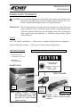
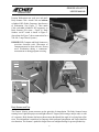
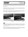
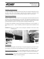
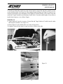
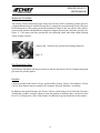
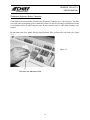
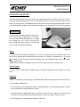
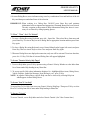
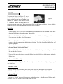
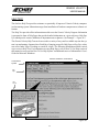
Position Workstation near work area and attach
Body Scanner Cable. Attach Cable end without
cylindrical RFI (Radio Frequency Interference)
to Workstation. (See Figure 7.) Then attach
Cable end with cylindrical RFI suppressor to
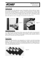
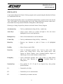
Body Scanner. (See arrow - Figure 8.) Body
Scanner ‘on/off’ switch is shown in Figure 9.
(Inset photo for Figure 7 shows connections for a
220-volt, 5 amp Genesis System.)
IMPORTANT: Computer and Body Scanner are
precision electronic tools. Movement of
components must be done with care. Do not
move Workstation during a ‘continuous’
measurement or during program accessing.
Figure 8
Power Cable
110 Volt
System
Body
Scanner
Cable
Power
Cable
220 Volt
System
Body
Scanner
Cable
Figure 9
Figure 7
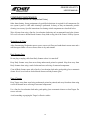
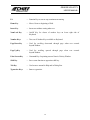
Body Scanner and Tray
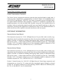
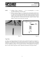
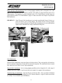
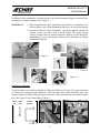
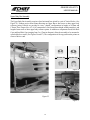
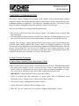
The Genesis Velocity system measures on the principle of triangulation. The Body Scanner houses
rotating Laser Lights that project toward light reflective Targets (each bearing a unique code) on vehicle’s structure. Body Scanner also houses photo sensors that identify the angle of revolving laser reflections. This information is transferred to computer which performs triangulation and Target identification functions. The Scanner’s parabolic design filters out sunlight allowing for greater productivity.
8