1
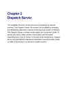
StellarMark IF-Series User Manual Version: 2.4 Released: Aug., 2013 4F., No.236, Fude 2nd Rd., Xizhi Dist., New Taipei City 22151, Taiwan 886-2-6616-6692 Fax:886-2-2694-6875 StellarMark IF-Series User Manual 1 Table of Contents CHAPTER 1 1.1 1.2 1.3 1.4 1.5 1.6 SAFETY ...................................................................................................... 4 Principles of a Fiber Laser................................................................ 5 Safety Ratings .................................................................................... 5 The Safety Interlock System............................................................. 5 Safety Labels ...................................................................................... 6 Safety Measures............................................................................... 10 Operating Environment ................................................................... 11 CHAPTER 2 UNPACKING & CONTENT..................................................................... 12 2.1 Unpacking and Unloading .............................................................. 13 2.2 Accessories Checklist .................................................................... 14 CHAPTER 3 MECHANICAL OVERVIEW .................................................................. 17 3.1 Laser Marker ..................................................................................... 18 3.1.1 LED Panel................................................................................. 19 3.1.2 Scan Lens................................................................................. 20 3.2 Control Unit ....................................................................................... 21 3.2.1 Optical fiber ............................................................................. 22 3.2.2 I/O Terminal Connector......................................................... 22 3.2.3 Rotary Attachment connector............................................. 23 3.2.4 USB connector........................................................................ 23 3.2.5 Mark On Fly terminal connector......................................... 23 3.3 Foot Print........................................................................................... 24 3.3.1 Laser Marker Foot Print........................................................ 24 3.3.2 Control Unit Foot Print ......................................................... 25 CHAPTER 4 4.1 4.2 Recommended Working Distance ................................................... 27 Pyramid Focus Tool ........................................................................ 28 CHAPTER 5 5.1 5.2 5.3 WORKING DISTANCE ............................................................................ 26 MACHINE SETUP .................................................................................... 30 Cable connection.............................................................................. 31 Powering Up the Machine ................................................................ 33 Control Unit operating instruction .................................................. 35 CHAPTER 6 SOFTWARE SETUP.................................................................................. 37 StellarMark IF-Series User Manual 2 6.1 6.2 6.3 6.4 Recommended Computer Configuration........................................ 38 Software Installation for Windows System..................................... 38 Software Installation for MAC System ............................................ 47 Waveform Parameter Adjustment.................................................... 55 CHAPTER 7 7.1 7.2 7.3 LENS ADJUSTMENT ............................................................................. 56 Import Lens Parameter..................................................................... 57 Lens Parameter Card........................................................................ 61 Lens Parameter Adjustment ............................................................ 64 CHAPTER 8 ERROR MESSAGE ................................................................................. 68 CHAPTER 9 EXTERNAL CONTROL........................................................................... 70 9.1 9.2 9.3 I/O Pin Assignment ........................................................................... 71 Laser Working Flow Chart.............................................................. 74 Laser Reaction Timing Diagram .................................................... 75 Start Fire delaying time................................................................ 75 Laser signal Output External device delaying time................... 76 Laser signal Output External device delaying time................... 76 CHAPTER 10 BASIC MAINTANENCE ........................................................................ 77 10.1 Regular spot check........................................................................... 78 10.2 Cleaning the scan lens ..................................................................... 78 StellarMark IF-Series User Manual 3 Chapter Safety Principles of a Fiber Laser Safety Ratings The Safety Interlock System Safety Labels Safety Measures Operating Environment StellarMark IF-Series User Manual 4 1.1 Principles of a Fiber Laser LASER is the acronym for Light Amplification by Stimulated Emission of Radiation. IF-series is equipped with the state-of-art fiber laser technology. A fiber laser is built with “all fiber” technology and uses a telecom grade diode to pump an optical fiber, and the fiber is doped with rare-earth elements as a gain medium to generate 1064nm laser light. Compared to the conventional DPSS technology, fiber laser is immune of misalignment and does not request any adjustment during operation. 1.2 Safety Ratings Laser marking systems that have the CDRH safety rating of Class 4 and the StellarMark IF-series has been equipped with a red guidance pointer. This red dot allows the operator to safely see the focal point of the laser beam. It gives Stellar Mark IF-series a rating of 3R when it is integrated with a safety door while operation. 1.3 The Safety Interlock System With the optional item of safety shield, it gives the StellarMark IF-series marking systems the capability to automatically shut off the laser when the door is opened. There are some magnets on the side of safety door, which activate this safety mechanism. Do not attempt to remove or modify these magnets or any other component of the safety interlock system. WARNING DO NOT operate the laser system if any component of the safety system is malfunctioning. DO NOT attempt to remove or modify any component of the safety interlock system. StellarMark IF-Series User Manual 5 1.4 Safety Labels According to CDRH standards, all fixed or removable covers that allow access to a laser beam must have appropriate laser warning labels attached to them. These warning labels must be clearly visible to the operator prior to removing the cover. Additional labels must be applied to the interior of the machine and be visible in the event when the covers are removed. A label clearly displaying the manufacturer’s name, date of manufacture, description of product, model number, serial number, and compliance statement must be attached to the outer surface of the machine. In compliance with CDRH standards, the required warning labels are affixed at the time of manufacture to the StellarMark IF-series, attached on appropriate locations. These labels are not to be modified in any way or removed for any reason. Please familiarize yourself with the specific labels and their locations on the machine. Below is a list of all the safety labels and their locations on the machine. Product Label This label is located at the side panel of machine. All the product information such as Serial Number, Model Numbers, Laser Power and Electric power can be found here. Before requiring any further tech support, always provide the service person with the information on this label. StellarMark IF-Series User Manual 6 StellarMark IF-Series User Manual 7 CDRH Label This label indicates the class level of CDRH. CE Label This label indicates the class level of CE StellarMark IF-Series User Manual 8 Warning Label Warning Label is written with all the necessary information to be aware of in every operation. Emergency Stop Label This label indicates the emergency stop button. You can find this label on the right upper side of the machine. StellarMark IF-Series User Manual 9 1.5 Safety Measures LASER RADIATION WARNING: Exposure to laser radiation may result in physical burns and severe eye damage. Proper use and regular maintenance of this machine is important to the safety of all people in the immediate area. Prior to operation, carefully read and familiarize yourself with the warning labels located on both your laser system and in this manual. Never leave the machine unattended during the laser cutting and marking process. The laser may ignite combustible materials. A well-maintained fire extinguisher and operational smoke or fire detector should be kept in the vicinity of the machine. Always wear safety goggles when the laser system is in operation. Reflective materials such as mirrors, enameled brass and anodized aluminum may partially-reflect some of the invisible laser radiation. Severe eye damage may occur if appropriate safety goggles are not worn. NOTE IF-series laser machine is shipped with a single pair of safety goggles. If additional safety goggles are required, please contact GCC directly or an authorized GCC distributor. If you wish to purchase one on your own, please make sure the safety goggles meet these requirements: 190 - 534 nm OD5+ 910 - 1,070nm OD6+ Visible Light Transmission: 23.5% Connect the machine to a properly grounded power outlet. Ensure the voltage of the power source is identical to the voltage of the machine. Do not attempt to modify or disassemble the laser module. Do not attempt to remove or modify any component of the machine’s laser interlock safety system. Ensure the immediate work area of the machine is well-ventilated. Odors, vapors, and dust are byproducts generated during the laser marking and cutting process. An exhaust system is recommended. Please contact GCC or your local GCC distributor for more information. StellarMark IF-Series User Manual 10 1.6 Do not laser heat-sensitive surfaces or materials that may generate toxic fumes, such as PVC and Teflon. Regularly clean and maintain your machine according to our cleaning and maintenance instructions. Doing so will ensure a machine that will operate effectively and safely over a long period of time. Operating Environment Please follow the guidelines when considering a suitable location to set the LaserPro StellarMark IF-series. Improper work environments may lead to operational malfunction and/or unsafe working conditions. The LaserPro StellarMark IF-series should be placed and operated in a clean environment, avoid places where the machine is exposed to high temperatures, dust, or high humidity Keep the machine where the room temperature is between 15 – 35 degrees Celsius or 59 – 95 degrees Fahrenheit. Avoid small, enclosed areas where a considerable amount of dust is present. Avoid areas where the humidity is above 70% or where the temperature is near the dew point. Setup the machine to be apart from the wall for at least 40cm (1.5 feet). Choose a flat surface that is not exposed to high levels of vibration. Be sure that your mounting platform has been securely fastened to the table, stand, or floor. Choose a location that is large enough to accommodate the machine, the computer and a work/storage table. Have a fire extinguisher close to the working location at all times. Make sure your smoke/fire detecting system is functioning. StellarMark IF-Series User Manual 11 Chapter Unpacking & Content Unpacking and Unloading Accessories Checklist StellarMark IF-Series User Manual 12 2.1 Unpacking and Unloading The Stellar Mark IF-series is shipped in one crate that contains one laser marker, one Control Unit, the software and all of the necessary accessories in an accessory kit. Control Unit Accessory Kit Laser Marker WARNING To prevent damage to the machine or personal injury, please get assistance when loading and unloading the shipping crate. NOTE Please save the original shipping crate in case it is needed for future transport or product servicing. StellarMark IF-Series User Manual 13 2.2 Accessories Checklist Before use, please check to see that the following items are shipped together correctly in the accessory kit. Item Quantity SCSI Cable 50pin length 2.5m 1 System Key 1 Laser Marker Power Cable (48V/20A/7Pin 2.5m) 1 G-Mark LibrarySoftware CD set 1 User’s Manual CD set 1 USB CABLE 1 AC Power Cable(Europe) 1 Power Cable (US) 1 Power Cable (AUS) 1 Pyramid Ruler Focus Tool 1 Check StellarMark IF-Series User Manual 14 Software Keypro for G-Mark Advance 1 Lens Cleaner 1 Lens Cleaning Paper 1 Cotton Bud (100pcs/ pack) 1 1064nm Goggle 1 Lens parameter Card 3 M6 screw plastic foot 4 Nut (M6xt5xS10). 4 I/O Terminal Platform(5ESDVM-10P) 1 I/O Terminal Cable 25 pin 1 Hex head screws driver 1 Warranty Card 1 Photos of key items: SCSI Cable G-Mark LibraryCD Set System Key User’s Manual CD Set Laser Marker Power Cable USB Cable StellarMark IF-Series User Manual 15 I/O Terminal Connector Pyramid Focus Tool Lens Parameter Card AC Power Cable Software Keypro Goggle I/O Terminal Cable StellarMark IF-Series User Manual 16 Chapter Mechanical Overview Laser Marker Control Unit Foot Print StellarMark IF-Series User Manual 17 Before you complete the installation, it is a good idea to become more familiar with the machine’s features and components. You should also make note of the new features that have been developed exclusively for the Stellar Mark. 3.1 Laser Marker Scan head LED Panel Laser Tube Scan Lens StellarMark IF-Series User Manual 18 3.1.1 LED Panel There are 3 LED lights on the panel and they will indicate out three working status of “Over Temp”, “Laser On” and “Power on” of the laser marker. Over Temp: When the red LED light is on, the laser marker will stop firing. Please turn off the master power of the laser marker and re-start it when the operating temperature is dropped below 35℃. Laser On: When laser is firing, the red LED light is on. Power On: When the laser is power on and the green LED light is on. StellarMark IF-Series User Manual 19 3.1.2 Scan Lens The StellarMarkTM IF-series gives you the choice of 3 sizes of scan lens to best suit your marking applications. IF-20 070 IF-20 110 IF-20 180 70x70mm 110x110mm 180x180mm IF-40 070 IF-40 110 IF-40 180 70x70mm 110x110mm 180x180mm The smaller field size scan lens will produce a smaller spot size with higher marking resolution. The larger field scan lens will produce a larger spot size with lower marking resolution. WARNING The scan lens is very fragile and must be careful while the cleaning and installing. Defective or unworkable scan lens due to abuse, mishandling, misuse, accident, alteration, negligence, improper installation, deficient cleaning or other causes will not be covered in the warranty. NOTE Scan lens is protected by a cover to prevent damage during shipment. Always remove the cover prior to use. StellarMark IF-Series User Manual 20 3.2 Control Unit Power On Ready Key Switch Emergency Stop Press the button to stop the laser in an emergency. To reset this button, rotate it to the direction of an arrow. Laser On I/O Terminal Rotary Attachment Mark On Fly SCSI USB Laser Marker Power Optical fiber StellarMark IF-Series User Manual 21 3.2.1 Optical fiber Optical fiber is doped with rare-earth elements as a gain medium to generate 1064nm laser light. WARNING 3.2.2 Excessively tight fiber bends (less than a 10 cm radius) will permanently damage and possibly ignite the fiber. Do not remove the two ends of fiber cable from the fiber module. I/O Terminal Connector The I/O pins are located at the back of Control Unit and they are the signal transmitting bridges between StellarMark and automation devices such as the conveyer for automation controls. 8 Output signal pins and 8 Input signal pins are provided for any designated automation purposes. It will allow laser marker to receive signals from or send out the signal to the other automation devices. StellarMark IF-Series User Manual 22 3.2.3 Rotary Attachment connector It is a connector which connects to GCC provided optional item of Rotary Attachment, It allows for precise 360° marking on round, cylindrical, or torus-shaped objects. 3.2.4 USB connector It is a connector which connects to a desktop PC or Notebook. 3.2.5 Mark On Fly terminal connector It is a connector which connects to an external device like encoder of conveyor. It allows Non-stop, “on-the-fly” marking parts maximizes productivities. StellarMark IF-Series User Manual 23 3.3 Foot Print 3.3.1 Laser Marker Foot Print StellarMark IF-Series User Manual 24 3.3.2 Control Unit Foot Print StellarMark IF-Series User Manual 25 Chapter Working Distance Recommended Working Distance Pyramid Focus Tool StellarMark IF-Series User Manual 26 4.1 Recommended Working Distance Due to the characteristics of the scan lens, a certain distance between the marking object and scan lens has to be set for an optimized output quality. The working distances for different scan lens are recommended as below: Scan lens 70x70mm 110x110mm 180x180mm A (Focus distance from bottom of the machine) 91.3mm ± 1mm 169.8 ± 2mm 313.3 ± 2mm B (Focus Tool Length) 128.3 ± 1mm 206.8 ± 2mm 350.3 ± 2mm NOTE In order to achieve the best output quality, the working distance must set precisely as recommended. For instance the 70x70 mm scan lens can only tolerate a distance which is +1mm different from the recommended working distance of 91.3mm. If the working distance is set and out of the recommended range, the output work produced will be unsatisfactory. StellarMark IF-Series User Manual 27 4.2 Pyramid Focus Tool The innovative and patened focus tool is an accessory unit for providing the best working distance on StellarMark IF-series. You will find the focus tool is located in accessory kit and an optimized length is set for your scan lens size when the machine is shipped. NOTE Fixed length will be varied depend on the size of scan lens. The fixed length of Pyramid Ruler equals the recommended working distance and you will no need to adjust the length. Screw the Pyramid Ruler beneath the laser marker and let the to be marked material touches the bottom screw of Pyramid Ruler, the distance between the two is the best working distance. Working Distance NOTE 1. With this tool, you can always have the best working distance for different materials by just place your desired marking material on the z axis table and move the z axis table up until the mark material touches the bottom screw of Pyramid Ruler. Bottom screw of Pyramid Ruler StellarMark IF-Series User Manual 28 NOTE 2. With its magnetic design, the “Pyramid Ruler” can easily be placed underneath the head of laser marker. StellarMark IF-Series User Manual 29 Chapter Machine Setup Cable Connection Powering Up the Machine StellarMark IF-Series User Manual 30 5.1 Cable connection Step 1. Connect the USB cable between a PC or Laptop and the Control Unit. Step 2. Connect the SCSI cable between the Control Unit and laser marker Step 3. Take out the “Mark on Fly” terminal connector from accessory kit and plug it if you want to activate the “mark on fly” function with an external device like conveyor. StellarMark IF-Series User Manual 31 Step 4. Plug the “rotary attachment” cable between Control Unit and the rotary attachment if you have this optional item in hand. Step 5. Plug the software keypro to a USB connector of you PC or Laptop. Step 6. Remove the cover of scan lens which is shipped along with StellarMark for protection. Take care not to damage the lens after removing the cover. StellarMark IF-Series User Manual 32 Step 7. Connect the Laser Marker power cable between the Control Unit and the laser marker.. 5.2 Powering Up the Machine CAUTION Make sure both StellarMark IF-series and the computer is turned off before connecting either to a power source. Step 1. Connect the male end of the power cord to a quality surge protector and the connect the surge protector to a proerly grounded outlet. Step 2. Step 3. Do the same for the computer system Connect the female end of the power cord into the machine’s power cable inlet located on the Control Unit. NOTE The Stellar Mark IF-series as been designed to work with 110~220 VAC, 50/60Hz, Max 5A StellarMark IF-Series User Manual 33 WARNING The connection to the AC power source must be the last step. Do not pull in or out the cable while the power is being turned on. Step 4. Turn on the master power of the Control Unit. NOTE Every time you turn off the power of laser marker, you are required to re-start G-Mark Library marking software. Because the connection between computer and control box is disconnected when the power is off, so the marking software is unable to control the laser firing. Step 5. Make sure the green light of “Power On” is on. StellarMark IF-Series User Manual 34 5.3 Control Unit operating instruction Step 1. Once the master power is on, please wait for 10 min to warm up the laser. This purpose is to ensure the laser power is reached to a stable firing status. Step 2. Make sure “Power On” LED is on Step 3. Turn the key switch on so you will be able to fire the laser OFF (Left) / ON (right) Step 4. Press ” LASER ON” button. The indicator light will alternately turn on and ready to lasing. StellarMark IF-Series User Manual 35 NOTE After finishing marking, press the LASER ON button again to off laser output. Please turn the key switch to the “Off” position if you would like to turn off the machine. StellarMark IF-Series User Manual 36 Chapter Software Setup Recommended Computer Configuration Software Installation for Windows System Software Installation for MAC System Waveform Parameter Adjustment StellarMark IF-Series User Manual 37 6.1 Recommended Computer Configuration The Stellar Mark is able to accommodate Laptop and compatible PC operating systems. Both the machine and G-Mark Basic TM software were designed to work best using a Windows based system with the following minimum requirements. Computer Configuration CPU Intel Pentium, 1GHz or above DRAM 1GB RAM or above CDROM One CD-ROM disk drive HDD 500 MB of free hard drive space SVGA Super VGA display (1204 x 768 min. resolution) Interface PC or Laptop G-Mark Library marking software 6.2 Software is designed for operating system Windows XP SP3 Windows 2000 VISTA 32 bit Windows 7 32 bit Software Installation for Windows System Please perform the following steps: Step 1. Take out the G-Mark installation CD from the accessories kit Step 2 Insert the G-Mark installation CD into the CD-ROM drive Wait a few seconds for the CD Manager to begin the Setup automatically StellarMark IF-Series User Manual 38 Step 3. Click on 32 bit or 64 bit version from the menu of the G-Mark installation CD depending on your operating system Step 4. Set the destination directory and click "Next>" StellarMark IF-Series User Manual 39 Step 5. Select "Next>" Step 6. Installing Step 7. At 95% completion of the installation, the ModelManger window will show up . StellarMark IF-Series User Manual 40 Step 8. Select your series & model type StellarMark IF-Series User Manual 41 Step 9. Click “OK” Step 10. Click “Finish” to complete the installation StellarMark IF-Series User Manual 42 Step 11. Once the installation is completed, you will find “Laser marking controller” at the lower right hand corner on your computer screen, this indicates the computer is able to communicate with StellarMark. Step 12. Open a new G-Mark file NOTE If “Laser marking controller” is not showing at the lower right hand corner of your computer screen, G-Mark will not be able to be activated. Please perform the following steps: A. Please go to “Control” and click on “System” StellarMark IF-Series User Manual 43 B. Then click on “Hardware” and go to the “Device manager” C. Please check if there is any “!” USB device from the below chart: StellarMark IF-Series User Manual 44 D. Then click on “USB Driver’ and click on right mouse button and update the driver. E. Click on ”Browse my computer for driver software” StellarMark IF-Series User Manual 45 F. Key in the specific path: “C:\Program Files\G-Mark Lib \Drivers\MC1. Then press “Next.. G. Press “Finish” and now you can activate the G-Mark software StellarMark IF-Series User Manual 46 6.3 Software Installation for MAC System MAC users can use GCC StellarMark machines by purchasing the Parallels Desktop software which allows you to install Windows OS in MAC computers and run Windows based software under MAC computer and output with G-Mark. Step 1. Purchase Parallels Desktops on its official website. Step 2. Install Parallels Desktops under Mac OS environment. StellarMark IF-Series User Manual 47 Step 3. Read Software License Agreement and press “Accept” to continue installation Step 4. Enter your Mac OS X User Name and Password then press “OK” StellarMark IF-Series User Manual 48 Step 5. Press “Active” Step 6. Press “OK” when activation is complete. StellarMark IF-Series User Manual 49 Step 7. Register Parallels Desktop StellarMark IF-Series User Manual 50 Step 8. Press “Register” and “OK” to complete the installation of Parallels Desktop. Step 9. Open Parallels Desktop (in the Applications folder) then choose File → New StellarMark IF-Series User Manual 51 Step 10. Press “Install Windows from DVD or image file” then press “continue” to install windows OS Step 11. Select CD-ROM drive with the Windows installation CD StellarMark IF-Series User Manual 52 Step 12. Enter the Windows OS product key Step 13. Select how you would like to run your Windows program. StellarMark IF-Series User Manual 53 Step 14. After the prior setting is complete the windows OS installation procedure will start automatically. Step 15. Windows OS installation is complete then you can refer to “6.2 Software Installation for windows system” to install G-Mark / G-Mark Library. StellarMark IF-Series User Manual 54 6.4 Waveform Parameter Adjustment Waveform is a setting available for fiber laser models. Adjusting the Waveform will affect the pulse width of the laser and so resulting effects. Waveform settings can be adjusted under the Marking Parameter tab of the Property Table. NOTE Waveform adjustment is only available for StellarMark IF-20SHS or IF40HHS models. Please refer to the product identification plate on the machine to confirm your model type. StellarMark IF-Series User Manual 55 Chapter Lens Adjustment Import Lens Parameter Lens Parameter Card Lens Parameter Adjustment StellarMark IF-Series User Manual 56 7.1 Import Lens Parameter Please perform the following steps: Step 1. Start the G-Mark program. Step 2. Select FileConfiguration Import/Export. Step 3. Check the Application Config, Lens Setting, Object Default and Machine Check Config selections. StellarMark IF-Series User Manual 57 Step 4. Click on the Folder location icon shown below. Step 5. Locate the Lens Parameter folder in the Installation CD and select OK. (The lens parameter folder is named with the serial number of your machine.). If there is no “Lens Parameter” folder found under G-Mark installation CD, please skip to follow ”7.2 Lens Parameter Card” instructions. StellarMark IF-Series User Manual 58 Step 6. Click the "Import" button. Step 7. Click on the "OK" button after the Status screen shows Complete. Step 8. Click on "OK" when the "Restart message prompts up. StellarMark IF-Series User Manual 59 Step 9. Click on the "Work Area" Tab under the Property Table after G-Mark restarts. Step 10. The Lens parameter can be found in the Lens list. (Named with the serial number of your machine.). Step 11. Click on "Apply" after selecting the Lens and the settings will be loaded. StellarMark IF-Series User Manual 60 7.2 Lens Parameter Card Before you start to operate the machine, the output scale of machine and the marking software must be adjusted to match each other. Or the marking lines will be distorted or will have an improper scale of the marking content. Step 1. Take out the lens parameter card from the accessory kit Step 2. Open G-Mark marking software Step 3. Click on work area from property table and press “Lens Manager…” StellarMark IF-Series User Manual 61 Step 4. Press “New” to create a new name for the lens and press “OK” Step 5. Click “Correction…” to settings lens StellarMark IF-Series User Manual 62 Step 6. Fill in the numbers that are showing on the card to the below table. Press “Exit” to save the settings of the lens NOTE If the size of scan lens is changed, the lens parameter will be varied, too. StellarMark IF-Series User Manual 63 7.3 Lens Parameter Adjustment Please perform the following steps to find the appropriate lens parameter when changing a different scan field of scan lens: Step 1. Create new name for the new lens. Step 2. Change the mark area and press “Exit” to save the settings Step 3. Mark the below pattern and check the output quality. StellarMark IF-Series User Manual 64 Step 4. If there is barrel square, go back to the “lens setup” to correct it. Step 5. If the figure becomes protuberant in X-axis, the X value will need to be Increased like 0.002; while if now it become indentation, the X value will have to be reduced to as 0.0014. Keep adjusting the value until it is acceptable. Step 6. If the square is trapezoid, go back to the “lens setup” to correct the irregular square. StellarMark IF-Series User Manual 65 Step 7. If the number is adjusted from 0.0 to 0.1, the adjustment range is from 0mm up to 0.5mm. (For 140x140mm scan lens) Keep adjusting the value until it is acceptable. Step 8. If there is an irregular parallelogram, go to the “lens parameter” under the Configure to correct the irregular angle. Step 9. Keep adjusting the value until it is acceptable. StellarMark IF-Series User Manual 66 Step 10. Measure the lengths of A, B, C, D and E of the square pattern. Make sure these lengths match to the expected length you set from the marking software. Step 11. If not, correct scale proportionally. StellarMark IF-Series User Manual 67 Chapter Error Message StellarMark IF-Series User Manual 68 The “Alarm” error indications represent the occurrence of errors which have arisen while the system is working abnormal. When the error occurs, an “Error message” window will pop out on G-Mark software and the laser will be unable to fire until the problems are solved. Once the problem is solved, “OK” button must be pressed to close the message window. The Alarm error indication includes: Error Indications X Scan head is abnormal Y Scan head is abnormal Base plate temperature fault Seed laser temperature fault Power Supply Fault Beam collimator fault StellarMark IF-Series User Manual 69 Chapter External Control I/O Pin Assignment Laser Working Flow Chart Laser Reaction Timing Diagram StellarMark IF-Series User Manual 70 9.1 I/O Pin Assignment I/O TYPE O1~O8 OUTPUT DESRIPTION There are 8 output signals (Stellar Mark External device) available to communicate with external devices. Alarm OUTPUT (Out) When Alarm is inactivated, the laser marker will send signal out. When Alarm is activated, the laser marker will send out a signal out. When marking software is opened, the Alarm will be activated and laser marker will send a signal out in the beginning of work. Until the “Execute” button is pressed and the “Marking” window jumps out on marking software, then alarm will change to “inactivated” (laser marker will send a signal out). StellarMark IF-Series User Manual 71 Ready OUTPUT (Out) When G-Mark Librarysoftware is opened, it will send out a signal out. When the “Marking” window jumps out and laser Marker is ready to fire; it will send a signal out. I1~I8 INPUT When laser marker is firing, it will send a signal out. There are 8 input signals (External device Stellar Mark) available to communicate with external devices STOP INPUT When Stop- pin and Ground pin are at short status, laser marker will stop working. START INPUT When Start- pin and Ground pin are at short status, laser marker will trigger the fire. This is terminal used to connect external emergency stop. E-Stop INPUT GND POWER Ground 24V POWER A 24V is available (Output) The Input and Output pins on the Control Unit are corresponding with the I and O signals on the G-Mark software as below: (1) Input pins Not Available The pin 9 ~ pin 16 from Input status are not available to communicate with laser marker. StellarMark IF-Series User Manual 72 (2) Output pins The pin 9 ~ pin 16 from Input status are not available to communicate with laser marker. Not Available NOTE High / Low definitions in G-Mark Library software StellarMark IF-Series User Manual 73 9.2 Laser Working Flow Chart StellarMark IF-Series User Manual 74 Definitions: A Power on B Time consuming between the “reading file” to the next step of “Ready to fire” will be depend on the size of working object. C~D After the file reading is completed, it will take less than < 1 µ sec for the external device to receive a “Ready” signal from the laser marker E It will take between 0.1m sec ~ 50m sec for laser to trigger the fire after receive the command of “Start” F Ready signal is OFF when laser is firing G Job is completed G~H 9.3 it will take about less than < 1 µ sec for the external device to receive a “Ready” signal from the laser marker I G-Mark marking software is closed J Power off Laser Reaction Timing Diagram ◆ Start Fire delaying time It will take about 0.1m sec <X< 50m sec to fire after receive the command of “Start” X START DELAY DUTY CYCLE RESTART \ STOP LASER WORKING 0.1 m sec < X < 50 m sec StellarMark IF-Series User Manual 75 ◆ Laser signal Output External device delaying time It will take about X < 1 µ sec for the external device to receive an output signal from the laser marker X OUTPUT DELAY USER RECEIVED X < 1μsec ◆ Laser signal Output External device delaying time It will take about 10 µ sec < X < 20 µ sec for the laser marker to receive an input signal from the external device X INPUT DELAY LASER WORKING 10μsec < X < 20μsec StellarMark IF-Series User Manual 76 Chapter Basic Maintanence StellarMark IF-Series User Manual 77 Keeping your StellarMark IF-series clean and well maintained will ensure quality output, consistent reliability, and extended product life. Smoke, dust or residue build-up inside the laser system or the mechanical components can cause a reduction in the laser power, reduced product life cycle, and a host of other avoidable problems. WARNING 10.1 Electrical shock may occur if you do not turn off and unplug the IF-40 before cleaning. Damage may occur to the system if you do not turn off and unplug the IF-series before cleaning. Always turn off and unplug the IF-40 before cleaning! Regular spot check Before each use, inspect the machine, the power and connector cables, and the working environment. Look for frays in cables, proper connections, and any abnormalities that could have an effect on marking performance and/or user safety. Be sure that the Stellar MarkTM is properly secured and mounted. If a problem ever arises with the G-Mark LibraryTM software or the Stellar MarkTM marking machine, be sure to notify your distributor as soon as possible. 10.2 Cleaning the scan lens Oil from hands and the residue that builds up on the scan lenses can distort the laser beam passing through, resulting in poor quality markings and may cause cracks by the uneven heat conduction. To clean the scan lens, simply remove the scan lens and inspect it for light and heavy residue marks. StellarMark IF-Series User Manual 78 To clean light residue marks, apply some lens cleaner on each side of the lens. Use a new, lint free cloth to remove the lens cleaner. Make sure that the cloth only travels in one direction to prevent scratching the scan lens. Let the lens dry before reattaching it to the StellarMarkTM. Be sure to clean only one side at a time. To clean a heavy residue mark, apply some lens cleaner on each side of the lens. Use a cotton swab to remove the caked on residue mark. Be careful not to scratch the lens. Use acetone if the lens cleaner will not remove the mark. After the mark is removed, follow the steps used to clean light residue marks in order to finish the cleaning. WARNING Acetone is an EXTREMELY FLAMMABLE LIQUID AND VAPOUR. The vapour is heavier than air and may spread long distances making distant ignition and flashback possible. NOTE Never touch the scan lens with your bare hand. The oils from your hand will distort the laser beam passing through the lens. Use finger cots or rubber gloves when cleaning. StellarMark IF-Series User Manual 79