1
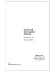
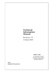
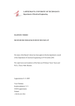
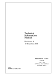
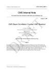
Technical Information Manual Revision n. 0 15 March 2010 MOD. DT5724 4 CHANNEL 14 BIT 100 MS/S DIGITIZER MANUAL REV.0 NPO: 00100/09:5724x.MUTx/00 CAEN will repair or replace any product within the guarantee period if the Guarantor declares that the product is defective due to workmanship or materials and has not been caused by mishandling, negligence on behalf of the User, accident or any abnormal conditions or operations. CAEN declines all responsibility for damages or injuries caused by an improper use of the Modules due to negligence on behalf of the User. It is strongly recommended to read thoroughly the CAEN User's Manual before any kind of operation. CAEN reserves the right to change partially or entirely the contents of this Manual at any time and without giving any notice. Disposal of the Product The product must never be dumped in the Municipal Waste. Please check your local regulations for disposal of electronics products. PRELIMINARY Document type: User's Manual (MUT) Title: Mod. DT5724 4 Channel 14bit - 100MS/s Digitizer Revision date: 15/03/2010 Revision: 0 TABLE OF CONTENTS 1. 2. GENERAL DESCRIPTION.........................................................................................................................7 1.1. OVERVIEW ...............................................................................................................................................7 1.2. BLOCK DIAGRAM .....................................................................................................................................9 TECHNICAL SPECIFICATIONS ............................................................................................................10 2.1. PACKAGING AND COMPLIANCY ..............................................................................................................10 2.2. POWER REQUIREMENTS ..........................................................................................................................10 2.3. FRONT AND BACK PANEL .......................................................................................................................10 2.4. EXTERNAL CONNECTORS ........................................................................................................................11 2.4.1. ANALOG INPUT connectors.........................................................................................................11 2.4.2. CONTROL connectors...................................................................................................................11 2.4.3. ADC REFERENCE CLOCK connectors .......................................................................................11 2.4.4. Digital I/O connectors ...................................................................................................................11 2.4.5. Optical LINK connector ................................................................................................................12 2.4.6. USB Port........................................................................................................................................12 2.4.7. 12V External..................................................................................................................................12 2.4.8. Spare Link......................................................................................................................................12 2.5. OTHER COMPONENTS .............................................................................................................................13 2.5.1. Displays .........................................................................................................................................13 TECHNICAL SPECIFICATIONS TABLE ...................................................................................................................14 3. FUNCTIONAL DESCRIPTION................................................................................................................15 3.1. ANALOG INPUT.......................................................................................................................................15 3.2. CLOCK DISTRIBUTION ............................................................................................................................15 3.2.1. Trigger Clock.................................................................................................................................16 3.3. ACQUISITION MODES .............................................................................................................................16 3.3.1. Acquisition run/stop.......................................................................................................................16 3.3.2. Acquisition Triggering: Samples and Events.................................................................................16 3.3.2.1. 3.3.3. Custom size events .................................................................................................................................... 18 Event structure...............................................................................................................................18 3.3.3.1. Header ....................................................................................................................................................... 18 3.3.3.2. Samples ..................................................................................................................................................... 18 3.3.3.3. 3.3.4. Event format examples.............................................................................................................................. 18 Memory FULL management..........................................................................................................20 3.4. ZERO SUPPRESSION ................................................................................................................................20 3.4.1. Zero Suppression Algorithm ..........................................................................................................20 3.4.1.1. Full Suppression based on the integral of the signal.................................................................................. 20 3.4.1.2. Full Suppression based on the amplitude of the signal.............................................................................. 20 3.4.1.3. 3.4.2. Zero Length Encoding ZLE....................................................................................................................... 22 Zero Suppression Examples...........................................................................................................24 NPO: 00100/09:5724x.MUTx/00 Filename: DT5724_REV0.DOC Number of pages: 44 Page: 3 PRELIMINARY Document type: User's Manual (MUT) Title: Mod. DT5724 4 Channel 14bit - 100MS/s Digitizer Revision date: 15/03/2010 Revision: 0 3.5. TRIGGER MANAGEMENT .........................................................................................................................28 3.5.1. Local channel auto-trigger ............................................................................................................28 3.5.1.1. 3.5.2. Trigger coincidence level .......................................................................................................................... 29 Trigger distribution .......................................................................................................................30 3.6. DATA TRANSFER CAPABILITIES ..............................................................................................................30 3.7. EVENTS READOUT ..................................................................................................................................31 3.8. OPTICAL LINK AND USB ACCESS ...........................................................................................................31 3.8.1. Software tools ................................................................................................................................32 4. BOARD INTERNAL REGISTERS...........................................................................................................33 4.1. REGISTERS ADDRESS MAP ......................................................................................................................33 4.2. CONFIGURATION ROM (0XF000-0XF088; R).........................................................................................34 4.3. CHANNEL N ZS_THRES (0X1N24; R/W) ................................................................................................35 4.4. CHANNEL N ZS_NSAMP (0X1N28; R/W) ...............................................................................................35 4.5. CHANNEL N THRESHOLD (0X1N80; R/W)................................................................................................35 4.6. CHANNEL N OVER/UNDER THRESHOLD (0X1N84; R/W) .........................................................................35 4.7. CHANNEL N STATUS (0X1N88; R)...........................................................................................................36 4.8. CHANNEL N AMC FPGA FIRMWARE (0X1N8C; R) ................................................................................36 4.9. CHANNEL N BUFFER OCCUPANCY (0X1N94; R)......................................................................................36 4.10. CHANNEL N DAC (0X1N98; R/W) .......................................................................................................36 4.11. CHANNEL N ADC CONFIGURATION (0X1N9C; R/W)...........................................................................36 4.12. CHANNEL CONFIGURATION (0X8000; R/W) ........................................................................................36 4.13. CHANNEL CONFIGURATION BIT SET (0X8004; W) ..............................................................................37 4.14. CHANNEL CONFIGURATION BIT CLEAR (0X8008; W) .........................................................................37 4.15. BUFFER ORGANIZATION (0X800C; R/W) ............................................................................................37 4.16. CUSTOM SIZE (0X8020; R/W) .............................................................................................................37 4.17. ACQUISITION CONTROL (0X8100; R/W)..............................................................................................38 4.18. ACQUISITION STATUS (0X8104; R) .....................................................................................................38 4.19. SOFTWARE TRIGGER (0X8108; W)......................................................................................................39 4.20. TRIGGER SOURCE ENABLE MASK (0X810C; R/W) ..............................................................................39 4.21. FRONT PANEL TRIGGER OUT ENABLE MASK (0X8110; R/W) .............................................................40 4.22. POST TRIGGER SETTING (0X8114; R/W) .............................................................................................40 4.23. FRONT PANEL I/O CONTROL (0X811C; R/W)......................................................................................40 4.24. CHANNEL ENABLE MASK (0X8120; R/W) ...........................................................................................40 4.25. ROC FPGA FIRMWARE REVISION (0X8124; R)..................................................................................41 4.26. DOWNSAMPLE FACTOR (0X8128; R/W) ..............................................................................................41 4.27. EVENT STORED (0X812C; R) ..............................................................................................................41 NPO: 00100/09:5724x.MUTx/00 Filename: DT5724_REV0.DOC Number of pages: 44 Page: 4 PRELIMINARY Document type: User's Manual (MUT) 5. Title: Mod. DT5724 4 Channel 14bit - 100MS/s Digitizer Revision date: 15/03/2010 Revision: 0 4.28. BOARD INFO (0X8140; R) ...................................................................................................................41 4.29. EVENT SIZE (0X814C; R)....................................................................................................................41 4.30. CONTROL (0XEF00; R/W) ...................................................................................................................41 4.31. STATUS (0XEF04; R) ..........................................................................................................................42 4.32. INTERRUPT STATUS ID (0XEF14; R/W)...............................................................................................42 4.33. INTERRUPT EVENT NUMBER (0XEF18; R/W) ......................................................................................42 4.34. BLOCK TRANSFER EVENT NUMBER (0XEF1C; R/W) ..........................................................................42 4.35. SCRATCH (0XEF20; R/W) ...................................................................................................................42 4.36. SOFTWARE RESET (0XEF24; W) .........................................................................................................42 4.37. SOFTWARE CLEAR (0XEF28; W) ........................................................................................................42 4.38. FLASH ENABLE (0XEF2C; R/W)..........................................................................................................43 4.39. FLASH DATA (0XEF30; R/W)..............................................................................................................43 4.40. CONFIGURATION RELOAD (0XEF34; W).............................................................................................43 INSTALLATION ........................................................................................................................................44 5.1. POWER ON SEQUENCE ...........................................................................................................................44 5.2. POWER ON STATUS ................................................................................................................................44 5.3. FIRMWARE UPGRADE..............................................................................................................................44 LIST OF FIGURES FIG. 1.1: MOD. D5724 DESKTOP WAVEFORM DIGITIZER .........................................................................................7 FIG. 1.1: MOD. D5724 BLOCK DIAGRAM .................................................................................................................9 FIG. 2.1: MOD. DT5724 FRONT PANEL ...................................................................................................................10 FIG. 2.2: MOD. DT5724 BACK PANEL .....................................................................................................................10 FIG. 2.3: MCX CONNECTOR ...................................................................................................................................11 FIG. 2.4: AMP CLK IN CONNECTOR......................................................................................................................11 FIG. 2.5: LC OPTICAL CONNECTOR ........................................................................................................................12 FIG. 3.1 INPUT DIAGRAM ........................................................................................................................................15 FIG. 3.2: CLOCK DISTRIBUTION DIAGRAM ..............................................................................................................15 FIG. 3.3: TRIGGER OVERLAP ..................................................................................................................................17 FIG. 3.4: EVENT ORGANIZATION ............................................................................................................................19 FIG. 3.5: ZERO SUPPRESSION BASED ON THE AMPLITUDE .......................................................................................21 FIG. 3.6: ZERO LENGTH ENCODING SAMPLES STORAGE .........................................................................................23 FIG. 3.7: ZERO SUPPRESSION EXAMPLE ..................................................................................................................24 FIG. 3.8: EXAMPLE WITH POSITIVE LOGIC AND NON-OVERLAPPING NLBK / NLFWD ..................................................24 NPO: 00100/09:5724x.MUTx/00 Filename: DT5724_REV0.DOC Number of pages: 44 Page: 5 PRELIMINARY Document type: User's Manual (MUT) Title: Mod. DT5724 4 Channel 14bit - 100MS/s Digitizer Revision date: 15/03/2010 Revision: 0 FIG. 3.9: EXAMPLE WITH NEGATIVE LOGIC AND NON-OVERLAPPING NLBK / NLFWD ................................................25 FIG. 3.10: EXAMPLE WITH POSITIVE LOGIC AND NON OVERLAPPING NLBK..............................................................26 FIG. 3.11: EXAMPLE WITH POSITIVE LOGIC AND OVERLAPPING NLBK .....................................................................27 FIG. 3.12: BLOCK DIAGRAM OF TRIGGER MANAGEMENT ........................................................................................28 FIG. 3.13: LOCAL TRIGGER GENERATION ................................................................................................................29 FIG. 3.14: LOCAL TRIGGER RELATIONSHIP WITH COINCIDENCE LEVEL ...................................................................30 FIG. 3.15: EXAMPLE OF BLOCK TRANSFER READOUT ..............................................................................................31 FIG. 3.16: OPTICAL LINK DAISY CHAIN ..................................................................................................................32 LIST OF TABLES TABLE 1.1: AVAILABLE ITEMS .................................................................................................................................8 TABLE 2.2: FRONT PANEL LEDS ............................................................................................................................13 TABLE 2.3: MOD. DT5724 TECHNICAL SPECIFICATIONS ........................................................................................14 TABLE 3.1: BUFFER ORGANIZATION ......................................................................................................................17 TABLE 4.1: ADDRESS MAP FOR THE MODEL DT5724 ............................................................................................33 TABLE 4.2: ROM ADDRESS MAP FOR THE MODEL DT5724 ..................................................................................34 NPO: 00100/09:5724x.MUTx/00 Filename: DT5724_REV0.DOC Number of pages: 44 Page: 6 PRELIMINARY Document type: User's Manual (MUT) Title: Mod. DT5724 4 Channel 14bit - 100MS/s Digitizer Revision date: 15/03/2010 Revision: 0 1. General description 1.1. Overview Fig. 1.1: Mod. D5724 Desktop Waveform Digitizer The Mod. DT5724 is a 4 Channel 14 bit 100 MS/s Desktop Waveform Digitizer with 2 Vpp dynamic range on single ended MCX coax. input connectors. The 2 Channel version (Mod. DT5724A) is also available. The DC offset adjustment (± 1.125V range) on each channel by 16bit DACs allows a right sampling of a bipolar (Vin=± 1.125V) up to a full positive (Vin= 0 ÷ +2.25V) or negative (Vin= 0 ÷ -2.25V) analog input swing without losing dynamic resolution. The module features a front panel clock In and a PLL for clock synthesis from internal/external references. The data stream is continuously written in a circular memory buffer. When triggered, the FPGA writes further N samples for the post trigger and freezes the buffer that can be read via USB or optical link. The acquisition can continue dead-timeless in a new buffer. Each channel has a SRAM memory buffer (512 kSamples/ch) divided in buffers of programmable size (1 - 1024). The readout (from USB or Optical link) of a frozen buffer is independent from the write operations in the active circular buffer (ADC data storage). Zero suppression and data reduction algorithms allow substantial savings in data amount readout and processing, rejecting samples smaller than programmable thresholds. DT5724 supports multi-board syncronization: an external reference clock can be distributed to all modules (CLK IN) and a common input (GPI) can be used to synchronize all ADC sampling clocks and events trigger time tag. DT5724 houses USB 2.0 and optical link interfaces. USB 2.0 allows data transfers up to 30 MB/s. The Optical Link supports transfer rate of 80 MB/s, and offer daisy-chain capability. Therefore it is possible to connect up to 8 ADC modules to an A2818 Optical Link Controller or 32 modules to an A3818 (4 channel version). NPO: 00100/09:5724x.MUTx/00 Filename: DT5724_REV0.DOC Number of pages: 44 Page: 7 PRELIMINARY Document type: User's Manual (MUT) Title: Mod. DT5724 4 Channel 14bit - 100MS/s Digitizer Revision date: 15/03/2010 Revision: 0 CAEN provides also for this model a Digital Pulse Processing firmware for Physics Applications. This feature allows to perform on-line processing on detector signal directly digitized. Table 1.1: Available items Code Description WDT5724AXAAA DT5724A - 2 Ch. 14 bit 100 MS/s Digitizer: 512kS/ch, C4, SE WDT5724XAAAA DT5724 - 4 Ch. 14 bit 100 MS/s Digitizer: 512kS/ch, C4, SE WA654XAAAAAA A654 - Single Channel MCX to LEMO Cable Adapter WA654K4AAAAA A654 KIT4 - 4 MCX TO LEMO Cable Adapter WA2818XAAAAA A2818 - PCI Optical Link WA3818AXAAAA A3818 - PCIe 1 Optical Link WA3818BXAAAA A3818 - PCIe 2 Optical Link WA3818CXAAAA A3818 - PCIe 4 Optical Link WAI2730XAAAA AI2730 - Optical Fibre 30 m. simplex WAI2720XAAAA AI2720 - Optical Fibre 20 m. simplex WAI2705XAAAA AI2705 - Optical Fibre 5 m. simplex WAI2703XAAAA AI2703 - Optical Fibre 30cm. simplex WAY2730XAAAA AY2730 - Optical Fibre 30 m. duplex WAY2720XAAAA AY2720 - Optical Fibre 20 m. duplex WAY2705XAAAA AY2705 - Optical Fibre 5 m. duplex WFWDPPCI02AA DPP CI Pack2 – Digital Pulse Processing with Charge Integration and Timing NPO: 00100/09:5724x.MUTx/00 Filename: DT5724_REV0.DOC Number of pages: 44 Page: 8 PRELIMINARY Document type: User's Manual (MUT) Title: Mod. DT5724 4 Channel 14bit - 100MS/s Digitizer Revision date: 15/03/2010 Revision: 0 1.2. Block Diagram FRONT PANEL x4 channels INPUTS ADC DAC AMC [FPGA] ADC & MEMORY CONTROLLER CLK IN MUX OSC CLOCK MANAGER (AD9520) LOCAL BUS BUFFERS TRG IN GPI GPO OPTICAL LINK ROC [FPGA] - Readout control - Optical link control - USB interface control - Trigger control - External interface control USB Fig. 1.1: Mod. D5724 Block Diagram The function of each block will be explained in detail in the subsequent sections. NPO: 00100/09:5724x.MUTx/00 Filename: DT5724_REV0.DOC Number of pages: 44 Page: 9 PRELIMINARY Document type: User's Manual (MUT) Title: Mod. DT5724 4 Channel 14bit - 100MS/s Digitizer Revision date: 15/03/2010 Revision: 0 2. Technical specifications 2.1. Packaging and Compliancy The unit is a Desktop module housed in a 154x50x164 mm3 alloy box. 2.2. Power requirements The module is powered via the external AC/DC stabilized, 230Vac – 12Vdc, 1.4A power supply (Alpha Elettronica Nr: SW18-12-60 CDZ-Nr: 97894). 2.3. Front and Back Panel Fig. 2.1: Mod. DT5724 front panel Fig. 2.2: Mod. DT5724 back panel NPO: 00100/09:5724x.MUTx/00 Filename: DT5724_REV0.DOC Number of pages: 44 Page: 10 PRELIMINARY Document type: User's Manual (MUT) Title: Mod. DT5724 4 Channel 14bit - 100MS/s Digitizer Revision date: 15/03/2010 Revision: 0 2.4. External connectors 2.4.1. ANALOG INPUT connectors Fig. 2.3: MCX connector Function: Analog input, single ended, input dynamics: 2.25Vpp Zin=50Ω Mechanical specifications: MCX connector (CS 85MCX-50-0-16 SUHNER) 2.4.2. CONTROL connectors Function: TRG IN: External trigger input (NIM/TTL, Zin= 50Ω) Mechanical specifications: 00-type LEMO connectors 2.4.3. ADC REFERENCE CLOCK connectors GND CLKCLK+ Fig. 2.4: AMP CLK IN Connector Function: CLK IN: External clock/Reference input, AC coupled (diff. LVDS, ECL, PECL, LVPECL, CML), Zdiff= 110Ω. Mechanical specifications: AMP 3-102203-4 AMP MODUII 2.4.4. Digital I/O connectors Function: • GPI: programmable front panel input (NIM/TTL, Zin=50Ω) NPO: 00100/09:5724x.MUTx/00 Filename: DT5724_REV0.DOC Number of pages: 44 Page: 11 PRELIMINARY Document type: User's Manual (MUT) Title: Mod. DT5724 4 Channel 14bit - 100MS/s Digitizer Revision date: 15/03/2010 Revision: 0 • GPO: programmable front panel output (NIM/TTL, Zin=50Ω); used as output for trigger propagation Mechanical specifications: 00-type LEMO connectors 2.4.5. Optical LINK connector Fig. 2.5: LC Optical Connector Mechanical specifications: LC type connector; to be used with Multimode 62.5/125µm cable with LC connectors on both sides Electrical specifications: Optical link for data readout and slow control with transfer rate up to 80MB/s; daisy chainable. 2.4.6. USB Port Mechanical specifications: B type USB connector Electrical specifications: USB 2.0 and USB 1.1 compliant 2.4.7. 12V External Mechanical specifications: RAPC722X SWITCHCRAFT PCB DC Power Jack Electrical specifications: +12V DC Input 2.4.8. Spare Link Mechanical specifications: 3M-7610-5002 connector NPO: 00100/09:5724x.MUTx/00 Filename: DT5724_REV0.DOC Number of pages: 44 Page: 12 PRELIMINARY Document type: User's Manual (MUT) Title: Mod. DT5724 4 Channel 14bit - 100MS/s Digitizer Revision date: 15/03/2010 Revision: 0 2.5. Other components 2.5.1. Displays The front panel hosts the following LEDs: Table 2.2: Front panel LEDs Name: CLK_IN NIM TTL USB LINK PLL _LOCK PLL _BYPS Colour: green green green green green/yellow green green RUN TRG DRDY BUSY green green green red NPO: 00100/09:5724x.MUTx/00 Function: External clock enabled. Standard selection for CLK, GPO, TRG IN, GPI. Standard selection for CLK, GPO, TRG IN, GPI. Data transfer activity Network present; Data transfer activity The PLL is locked to the reference clock The reference clock drives directly ADC clocks; the PLL circuit is switched off and the PLL_LOCK LED is turned off. RUN bit set (see § 4.18) Triggers are accepted Event/data (depending on acquisition mode) are present in the Output Buffer All the buffers are full Filename: DT5724_REV0.DOC Number of pages: 44 Page: 13 PRELIMINARY Document type: User's Manual (MUT) Title: Mod. DT5724 4 Channel 14bit - 100MS/s Digitizer Revision date: 15/03/2010 Revision: 0 Technical specifications table Table 2.3: Mod. DT5724 technical specifications Packaging 3 Desktop module; 154x50x164 mm (WxHxD), Weight: 680 gr Analog Input 4 channels (MCX 50 Ohm) Single-ended Input range: 2.25 Vpp; Bandwidth: 40 MHz. Programmable DAC for Offset Adjust x ch., adjustment range: ±1.125V Digital Conversion Resolution: 14 bit; Sampling rate: 10 to 100 MS/s simultaneously on each channel; multi board synchronization ADC Sampling Clock generation Three operating modes: - PLL mode - internal reference (50 MHz loc. oscillator). - PLL mode - external reference on CLK_IN (Jitter<100ppm). - PLL Bypass mode: Ext. clock on CLK_IN drives directly ADC clocks (Freq.: 10 ÷ 250 MHz). Digital I/O CLK_IN (AMP Modu II): - AC coupled differential input clock LVDS, ECL, PECL, LVPECL, CML (single ended NIM/TTL available ) - Jitter<100ppm TRG_IN (LEMO 50 Ohm, NIM/TTL) GPI/GPO (LEMO 50 Ohm, NIM/TTL) Memory Buffer 512K sample/ch Multi Event Buffer Programmable event size and pre-post trigger. Divisible into 1 ÷ 1024 buffers. Readout of Frozen buffer independent from write operations in the active buffer (ADC data storage) Trigger Common Trigger - TRG_IN (External signal) - Software (from USB or Optical Link) - Self trigger (Internal threshold auto-trigger) Daisy chain trigger propagation among boards (using GPO) Trigger Time Stamp 32bit – 8ns (34s range) Allows data alignment and consistency across multiple DT5724 modules: Multi Modules Synchronization - CLK_IN allows the synchronization to a common clock source - GPI ensures Trigger time stamps and start acquisition times alignment USB interface USB2.0 and USB1.1 compliant Up to 30 MB/s transfer rate Optical Link CAEN proprietary protocol, up to 80 MB/s transfer rate, with Optical Link Controller (Mod. A2818/A3818). Upgrade Firmware can be upgraded via Optical Link or USB interface Software General purpose C and LabView Libraries Demo and Software Tools for Windows and Linux Electrical Power Voltage range: 12 ± 10% Vdc NPO: 00100/09:5724x.MUTx/00 Filename: DT5724_REV0.DOC Number of pages: 44 Page: 14 PRELIMINARY Document type: User's Manual (MUT) Title: Mod. DT5724 4 Channel 14bit - 100MS/s Digitizer Revision date: 15/03/2010 Revision: 0 3. Functional description 3.1. Analog Input Input dynamic is 2.25Vpp (Zin= 50 Ω). A 16bit DAC allow to add up to ±1.125V (±5V with high-range input) DC offset in order to preserve the full dynamic range also with unipolar positive or negative input signals. The input bandwidth ranges from DC to 40 MHz (with 2nd order linear phase anti-aliasing low pass filter). Input MCX 50? Positive Unipolar ? OpAmp ? ADC FPGA Vref DAC DAC = FSR +2.25 14 bit 16 bit +1.125 0 -1.125 Negative Unipolar -2.25 DAC = 0 Bipolar DAC = FSR/2 Fig. 3.1 Input diagram 3.2. Clock Distribution Fig. 3.2: Clock distribution diagram NPO: 00100/09:5724x.MUTx/00 Filename: DT5724_REV0.DOC Number of pages: 44 Page: 15 PRELIMINARY Document type: User's Manual (MUT) Title: Mod. DT5724 4 Channel 14bit - 100MS/s Digitizer Revision date: 15/03/2010 Revision: 0 The module clock distribution takes place on two domains: OSC-CLK and REF-CLK; the former is a fixed 50MHz clock provided by an on board oscillator, the latter provides the ADC sampling clock. OSC-CLK handles Local Bus (communication between motherboard and mezzanine boards; see red traces in the figure above). REF-CLK handles ADC sampling, trigger logic, acquisition logic (samples storage into RAM, buffer freezing on trigger) through a clock chain. Such domain can use either an external (via front panel signal) or an internal (via local oscillator) source, in the latter case OSC-CLK and REF-CLK will be synchronous (the operation mode remains the same anyway). DT5724 uses an integrated phase-locked-loop (PLL) and clock distribution device (AD9520). It is used to generate the sampling clock for ADCs (SAMP-CLK0/SAMPCLK1) and trigger logic synchronization clock (TRG-CLK). Both clocks can be generated from the internal oscillator or from external clock input (CLK IN). By default, board uses the internal clock as PLL reference (REF-CLK). External clock can be selected by register access. AD9520 configuration can be changed and stored into non-volatile memory. AD9520 configuration change is primarly intended to be used for external PLL reference clock frequency change: DT5724 locks to an external 50 MHz clock with default AD9520 configuration. Please contact CAEN ([email protected]) for more information and configuration tools. Refer also to AD9520 data sheet for more details: http://www.analog.com/UploadedFiles/Data_Sheets/AD9520.pdf 3.2.1. Trigger Clock TRG-CLK signal has a frequency equal to ½ of SAMP-CLK; therefore a 2 samples “uncertainty” occurs over the acquisition window. 3.3. Acquisition Modes 3.3.1. Acquisition run/stop The acquisition can be started in two ways, according to Acquisition Control register Bits [0] setting (see § 4.17): − setting the RUN/STOP bit (bit[2]) in the Acquisition Control register (bits [0] of Acquisition Control must be set to REGISTER-CONTROLLED RUN MODE − driving GPI signal high (bit 0 of Acquisition Control must be set to 1, GPI CONTROLLED RUN MODE) Subsequently acquisition is stopped either: − resetting the RUN/STOP bit (bit 2 in the Acquisition Control register (bit 0 of Acquisition Control must be set to REGISTER-CONTROLLED RUN MODE) − driving GPI signal low (bit 0 of Acquisition Control set to 1, GPI CONTROLLED RUN MODE) 3.3.2. Acquisition Triggering: Samples and Events When the acquisition is running, a trigger signal allows to: − store a Trigger Time Tag (TTT): the value of a 32 bit counter which steps on with the sampling clock and represents a time reference NPO: 00100/09:5724x.MUTx/00 Filename: DT5724_REV0.DOC Number of pages: 44 Page: 16 PRELIMINARY Document type: User's Manual (MUT) − − Title: Mod. DT5724 4 Channel 14bit - 100MS/s Digitizer Revision date: 15/03/2010 Revision: 0 increment the EVENT COUNTER (see § 4.26) fill the active buffer with the pre/post-trigger samples, whose number is programmable via Post Trigger Setting register (see § 4.22); the Acquisition window width is determined via Buffer Organization register setting (see § 4.15,); then the buffer is frozen for readout purposes, while acquisition continues on another buffer. Table 3.1: Buffer Organization REGISTER (see § 4.15) 0x00 0x01 0x02 0x03 0x04 0x05 0x06 0x07 0x08 0x09 0x0A BUFFER NUMBER 1 2 4 8 16 32 64 128 256 512 1024 SIZE of one BUFFER (samples) 512K 256K 128K 64K 32K 16K 8K 4K 2K 1K 512 An event is therefore composed by the trigger time tag, pre- and post-trigger samples and the event counter. Overlap between “acquisition windows” may occur (a new trigger occurs while the board is still storing the samples related to the previous trigger); this overlap can be either rejected or accepted (programmable). If the board is programmed to accept the overlapped triggers, as the “overlapping” trigger arrives, the current active buffer is filled up, then the samples storage continues on the subsequent one. In this case events will not have all the same size (see figure below). EVENT n EVENT n+1 EVENT n+2 Recorded Not Recorded TRIGGER PRE POST ACQUISITION WINDOW Overlapping Triggers Fig. 3.3: Trigger Overlap A trigger can be refused for the following causes: − acquisition is not active − memory is FULL and therefore there are no available buffers − the required number of samples for building the pre-trigger of the event is not reached yet; this happens typically as the trigger occurs too early either with respect NPO: 00100/09:5724x.MUTx/00 Filename: DT5724_REV0.DOC Number of pages: 44 Page: 17 PRELIMINARY Document type: User's Manual (MUT) − Title: Mod. DT5724 4 Channel 14bit - 100MS/s Digitizer Revision date: 15/03/2010 Revision: 0 to the RUN_ACQUISITION command (see § 3.3.1) or with respect to a buffer emptying after a MEMORY_FULL status the trigger overlaps the previous one and the board is not enabled for accepting overlapped triggers As a trigger is refused, the current buffer is not frozen and the acquisition continues writing on it. The Event Counter can be programmed in order to be either incremented or not. If this function is enabled, the Event Counter value identifies the number of the triggers sent (but the event number sequence is lost); if the function is not enabled, the Event Counter value coincides with the sequence of buffers saved and readout. 3.3.2.1. Custom size events It is possible to make events with a number of Memory locations, which depends on Buffer Organization register setting (see § 4.15) smaller than the default value. One memory location contains two ADC samples and the maximum number of memory locations NLOC is therefore half the maximum number of samples per block NS = 512K/Nblocks. Smaller NLOC values can be achieved by writing the number of locations NLOC into the Custom Size register (see § 4.16). NLOC = 0 means “default size events”, i.e. the number of memory locations is the maximum allowed. NLOC = N1, with the constraint 0<N1<½NS, means that one event will be made of 2⋅N1 samples. 3.3.3. Event structure An event is structured as follows: − Header (4 32-bit words) − Data (variable size and format) The event can be readout either via USB or Optical Link; data format is 32 bit long word, therefore each long_word contains 2 samples. 3.3.3.1. Header It is composed by four words, namely: − Size of the event (number of 32 bit long words) − Bit24; data format: 0= normal format; 1= Zero Length Encoding data compression method enabled; Channel Mask (=1: channels participating to event; ex CH2 and CH3 participating→Ch Mask: 0xC, this information must be used by the software to acknowledge which channel the samples are coming from) − Event Counter: It is the trigger counter; it can count either accepted triggers only, or all triggers (see § 4.16). − Trigger Time Tag: It is a 32 bit counter (31 bit count + 1 overflow bit), which is reset as acquisition starts and is incremented at each sampling clock hit. It is the trigger time reference. 3.3.3.2. Samples Stored samples; data from masked channels are not read. 3.3.3.3. Event format examples The event format is shown in the following figure (case of 3 channels enabled, with Zero Length Encoding disabled and enabled respectively): NPO: 00100/09:5724x.MUTx/00 Filename: DT5724_REV0.DOC Number of pages: 44 Page: 18 PRELIMINARY Document type: User's Manual (MUT) Title: Mod. DT5724 4 Channel 14bit - 100MS/s Digitizer Revision date: 15/03/2010 Revision: 0 ZERO LENGHT ENCODING disabled 31 30 29 28 27 26 25 24 23 22 21 20 19 18 17 16 15 14 13 12 11 10 9 8 7 6 5 4 3 2 1 0 EVENT SIZE RES reserved 0 0 0 0 0 0 0 SAMPLE [N-1] – CH[0] SAMPLE [1] – CH[1] [1] – CH[0] [3] – CH[0] SAMPLE [0] – CH[0] [2] – CH[0] SAMPLE [N-2 ] – CH [0] SAMPLE [0] – CH[1] [3] – CH[1] 0 0 0 0 0 0 [N-1] – CH[1] 0 0 SAMPLE [N-2 ] – CH [1] [1] – CH[3] [3] – CH[3] 0 0 0 0 SAMPLE [0] – CH[3] SAMPLE [2] – CH[3] SAMPLE SAMPLE SAMPLE 0 0 SAMPLE [N-1] – CH[3] SAMPLE [2] – CH[1] 0 0 SAMPLE DATA CH3 0 0 0 0 CH. MASK DATA CH1 SAMPLE SAMPLE EVENT COUNTER TRIGGER TIME TAG 0 0 SAMPLE SAMPLE 0 0 DATA CH0 0 0 0 0 0 0 0 0 0 0 reserved HEADER 1 0 1 0 BOARD -ID [N-2 ] – CH [3] ZERO LENGHT ENCODING enabled 31 30 29 28 27 26 25 24 23 22 21 20 19 18 17 16 15 14 13 12 11 10 9 8 7 6 5 4 3 2 1 0 EVENT SIZE Res. 1 reserved EVENT COUNTER TRIGGER TIME TAG reserved 0 0 0 0 CH. MASK HEADER 1 0 1 0 BOARD -ID SIZE 0 0 SAMPLE [1] – CH[0] 0 0 SAMPLE [N-1] – CH[0] 0 0 SAMPLE [0] – CH[0] CONTROL WORD 0 0 D AT A C H 0 CONTROL WORD SAMPLE [N-2 ] – CH [0] SIZE SAMPLE [1] – CH[1] 0 0 SAMPLE [0] – CH[1] CONTROL WORD 0 0 SAMPLE 0 0 [N-1] – CH[1] D AT A C H 1 CONTROL WORD 0 0 SAMPLE [N-2 ] – CH [1] SIZE 0 0 SAMPLE 0 0 SAMPLE [N-1] – CH[3] 0 0 [1] – CH[3] SAMPLE [0] – CH[3] CONTROL WORD 0 0 SAMPLE D AT A C H 3 CONTROL WORD [N-2 ] – CH [3] Fig. 3.4: Event Organization NPO: 00100/09:5724x.MUTx/00 Filename: DT5724_REV0.DOC Number of pages: 44 Page: 19 PRELIMINARY Document type: User's Manual (MUT) 3.3.4. Title: Mod. DT5724 4 Channel 14bit - 100MS/s Digitizer Revision date: 15/03/2010 Revision: 0 Memory FULL management Bit5 of Acquisition Control register (see § 4.16), allows to select Memory FULL management mode: In Normal Mode the board becomes full, whenever all buffers are full (see § 4.15); otherwise (“Always one buffer free” mode) it is possible to always keep one buffer free: board becomes full, whenever N-1buffers are full; with N = nr. of blocks (see § 4.15). In Normal Mode, the board waits until one buffer is filled since FULL status is exited (whether the trigger is overlapped or not). The board exits FULL status at the moment which the last datum from the last channel participating to the event is read. In “Always one buffer free” mode, one buffer cannot be used (therefore it is NOT POSSIBLE, with this mode, to set Buffer Code to 0000; see § 4.15), but this allows to eliminate dead time when FULL status is exited. 3.4. Zero suppression The board implements three algorithms of “Zero Suppression” and “Data Reduction” - Full Suppression based on the integral of the signal (ZS_INT) - Full Suppression based on the signal amplitude (ZS_AMP) - Zero Length Encoding (ZLE), The algorithm to be used is selected via Configuration register (see § 0), and its configuration takes place via two more registers (CHANNEL n ZS_THRES and CHANNEL n ZS_NSAMP). When using ZS_AMP and ZS_ZLE algorithms, it must be noticed that that one datum (32 bit long word) contains 2 samples: therefore, depending also on trigger polarity (settings of bit31 of Channel n ZS_THRES register), threshold is crossed if: Positive Logic: one datum is considered OVER threshold if at least one sample is higher or equal to threshold. Negative Logic: one datum is considered UNDER threshold if at least one sample is lower than threshold. 3.4.1. 3.4.1.1. Zero Suppression Algorithm Full Suppression based on the integral of the signal Full Suppression based on the integral of the signal allows to discard data from one channel if the sum of all the samples (from this channel) is smaller than the threshold set by the User (see § 4.3). It is also possible to configure the algorithm with “negative” logic: in this case the data from that channel are discarded if the sum of all the samples (from that channel) is higher than the threshold set by the User (see § 4.3). 3.4.1.2. Full Suppression based on the amplitude of the signal Full Suppression based on the signal amplitude allows to discard data from one channel if the signal does not exceed the programmed threshold for Ns subsequent data at least (Ns is programmable, see § 4.4). It is also possible to configure the algorithm with “negative” logic: in this case the data from that channel are discarded if the signal does not remain under the programmed threshold for Ns subsequent data at least. The following figure shows an example of Full Suppression based on the amplitude of the signal: the algorithm has positive logic; CH0..CH3 are enabled for acquisition, therefore NPO: 00100/09:5724x.MUTx/00 Filename: DT5724_REV0.DOC Number of pages: 44 Page: 20 PRELIMINARY Document type: User's Manual (MUT) Title: Mod. DT5724 4 Channel 14bit - 100MS/s Digitizer Revision date: 15/03/2010 Revision: 0 the Channel Mask field in the Header allows to acknowledge which channel the data are coming from; see also § 3.3.3 for data format details. Settings: Channel Configuration bits [19:16] = 0x3 (ZS_AMP mode) CH Enable Mask = 0xF Trigger Source Enable Mask bits [31:16] = 0x4000 Trigger Source Enable Mask bits [15:0] = 0x0 Channel n ZS_THRES bit 31 = 0 Channel n ZS_THRES bits [13:0] = Threshold Channel n ZS_NSAMP bits [31:0] = Ns Threshold Threshold CH2 TRG TRG CH0 N1>Ns N2>Ns Threshold CH3 Threshold TRG TRG CH1 OUTPUT DATA: 31 30 29 28 27 26 25 24 23 22 21 20 19 18 17 16 15 14 13 12 11 10 9 8 7 6 5 4 3 2 1 0 RES reserved EVENT SIZE 0 reserved EVENT COUNTER TRIGGER TIME TAG 0 0 0 0 CH. MASK HEADER 1 0 1 0 BOARD -ID Channel Mask = 0x5 DATA CH0 DATA CH2 Fig. 3.5: Zero Suppression based on the amplitude NPO: 00100/09:5724x.MUTx/00 Filename: DT5724_REV0.DOC Number of pages: 44 Page: 21 PRELIMINARY Document type: User's Manual (MUT) Title: Mod. DT5724 4 Channel 14bit - 100MS/s Digitizer 3.4.1.3. Revision date: 15/03/2010 Revision: 0 Zero Length Encoding ZLE Zero Length Encoding allows to transfer the event in compressed mode, discarding either the data under the threshold set by the User (positive logic) or the data over the threshold set by the User (negative logic). With Zero length encoding it is also possible to set NLBK (LOOK BACK), the number of data to be stored before the signal crosses the threshold and/or, NLFWD (LOOK FORWARD), the number of data to be stored after the signal crosses the threshold (see § 4.3). In this case the event of each channel has a particular format which allows the construction of the acquired time interval: Total size of the event (total number of transferred data) Control word [stored valid data, if control word is “good”] Control word [stored valid data, if control word is “good”] ... The total size is the number of 32 bit data that compose the event (including the size itself). The control word has the following format: Bit Function 0: skip [31] 1: good [30:21] 0 [20:0] stored/skipped words If the control word type is “good”, then it will be followed by as many data as those indicated in the “stored/skipped words” field; if the control word type is “skip” then it will be followed by a “good” control world, unless the end of event is reached. IMPORTANT NOTE: the maximum allowed number of control words is 62 (14 for piggy back release 0.6 and earlier); therefore the ZLE is active within the event until the 14th transition between a “good” and a “skip” zone (or between a “skip” and a “good” zone). All the subsequent samples are considered “good” and stored. The following figure shows an example of Zero Length Encoding: the algorithm has positive logic; CH0..CH3 are enabled for acquisition, therefore the Channel Mask field in the Header allows to acknowledge which channel the data are coming from; see also § 3.3.3 for data format details. NPO: 00100/09:5724x.MUTx/00 Filename: DT5724_REV0.DOC Number of pages: 44 Page: 22 PRELIMINARY Document type: User's Manual (MUT) Title: Mod. DT5724 4 Channel 14bit - 100MS/s Digitizer Revision date: 15/03/2010 Revision: 0 Settings: CH Enable Mask = 0xF Channel Configuration bits [19:16] = 0x2 (ZLE mode) Trigger Source Enable Mask bits [31:16] = 0x4000 Trigger Source Enable Mask bits [15:0] = 0x0 Channel n ZS_THRES bit 31 = 0 Channel n ZS_THRES bits [13:0] = Threshold Channel n ZS_NSAMP bits [31:16] = Nlfwd Channel n ZS_NSAMP bits [15:0] = Nlbk Threshold Threshold CH2 Nlbk TRG TRG CH0 Nlbk Nlfwd Threshold CH3 Threshold TRG TRG CH1 Nlfwd OUTPUT DATA: 31 30 29 28 27 26 25 24 23 22 21 20 19 18 17 16 15 14 13 12 11 10 9 8 7 6 5 4 3 2 1 0 RES reserved 1 EVENT SIZE reserved EVENT COUNTER TRIGGER TIME TAG 0 0 0 0 CH. MASK HEADER 1 0 1 0 BOARD-ID Channel Mask = 0x5 DATA CH0 DATA CH2 Fig. 3.6: Zero Length Encoding samples storage NPO: 00100/09:5724x.MUTx/00 Filename: DT5724_REV0.DOC Number of pages: 44 Page: 23 PRELIMINARY Document type: User's Manual (MUT) 3.4.2. Title: Mod. DT5724 4 Channel 14bit - 100MS/s Digitizer Revision date: 15/03/2010 Revision: 0 Zero Suppression Examples If the input signal is the following: Fig. 3.7: Zero Suppression example If the algorithm works in positive logic, and NLBK < N1 ; NLFWD < N5 ; NLBK + NLFWD < N3 ; Fig. 3.8: Example with positive logic and non-overlapping NLBK / NLFWD then the readout event is: N'2 + N'4 + 5 (control words) + 1 (size) Skip N1 - NLBK Good N'2 = NLBK + N2 + NLFWD ... N'2 words with samples over threshold Skip N3 - NLFWD - NLBK Good N'4 = NLBK + N4 + NLFWD ... N'4 words with samples over threshold Skip N5 - NLFWD NPO: 00100/09:5724x.MUTx/00 Filename: DT5724_REV0.DOC Number of pages: 44 Page: 24 PRELIMINARY Document type: User's Manual (MUT) Title: Mod. DT5724 4 Channel 14bit - 100MS/s Digitizer Revision date: 15/03/2010 Revision: 0 If the algorithm works in negative logic, and NLBK + NLFWD < N2 ; NLBK + NLFWD < N4 ; Fig. 3.9: Example with negative logic and non-overlapping NLBK / NLFWD then the readout event is: N'1 + N'3 + N'5 + 5 (control words) + 1 (size) Good N'1 = N1 + NLFWD ... N'1 words with samples under threshold Skip N2 - NLFWD - NLBK Good N'3 = NLBK + N3 + NLFWD ... N'3 words with samples under threshold Skip N4 - NLFWD - NLBK Good N'5 = NLBK + N5 ... N'5 words with samples under threshold In some cases the number of data to be discarded can be smaller than NLBK and NLFWD : 1) If the algorithm works in positive logic, and N1 ≤ NLBK < N3 ; NLFWD = 0 ; NPO: 00100/09:5724x.MUTx/00 Filename: DT5724_REV0.DOC Number of pages: 44 Page: 25 PRELIMINARY Document type: User's Manual (MUT) Title: Mod. DT5724 4 Channel 14bit - 100MS/s Digitizer Revision date: 15/03/2010 Revision: 0 Fig. 3.10: Example with positive logic and non overlapping NLBK then the readout event is: N1 +N2 + N'4 + 5 (control words) + 1 (size) Good N1 + N2 ... N1 + N2 words with samples over threshold Skip N3 - NLBK Good N'4 = NLBK + N4 ... N'4 words with samples over threshold Skip N5 2) If the algorithm works in positive logic, and NLBK = 0 ; N5 ≤ NLFWD < N3 ; then the readout event is: N'2 + N4 +N5 + 5 (control words) + 1 (size) Skip N1 Good N'2 = N2 + NLFWD ... N'2 words with samples over threshold Skip N3 - NLFWD Good N4 + N5 ... N4 + N5 words with samples over threshold 3) If the algorithm works in positive logic, and NLBK = 0 ; N3 ≤ NLFWD < N5 ; then the readout event is: N'2 + 3 (control words) + 1 (size) Skip N1 Good N'2 = N2 + N3 + N4 + NLFWD ... N'2 words with samples over threshold Skip N5 - NLFWD 4) If the algorithm works in positive logic, and NPO: 00100/09:5724x.MUTx/00 Filename: DT5724_REV0.DOC Number of pages: 44 Page: 26 PRELIMINARY Document type: User's Manual (MUT) Title: Mod. DT5724 4 Channel 14bit - 100MS/s Digitizer Revision date: 15/03/2010 Revision: 0 N3 ≤ NLBK < N1 ; NLFWD = 0 ; Fig. 3.11: Example with positive logic and overlapping NLBK then the readout event is: N'2 +N'4 + 4 (control words) + 1 (size) Skip N1 - NLBK Good N'2 = NLBK + N2 ... N'2 words with samples over threshold Good N'4 = N3 + N4 ... N'4 words with samples over threshold Skip N5 N.B: In this case there are two subsequent “GOOD” intervals. 5) If the algorithm works in positive logic, and 0 < NLBK < N1 ; NLFWD < N5 ; NLBK + NLFWD ≥ N3 . then the readout event is: N'2 + N'4 + 4 (control words) + 1 (size) Skip N1 - NLBK Good N'2 = NLBK + N2 + NLFWD ... N'2 words with samples over threshold Good N'4 = (N3 - NLFWD ) + N4 + NLFWD ... N'4 words with samples over threshold Skip N5 - NLFWD N.B: In this case there are two subsequent “GOOD” intervals. These examples are reported with positive logic; the compression algorithm is the same also working in negative logic. NPO: 00100/09:5724x.MUTx/00 Filename: DT5724_REV0.DOC Number of pages: 44 Page: 27 PRELIMINARY Document type: User's Manual (MUT) Title: Mod. DT5724 4 Channel 14bit - 100MS/s Digitizer Revision date: 15/03/2010 Revision: 0 3.5. Trigger management All the channels in a board share the same trigger: this means that all the channels store an event at the same time and in the same way (same number of samples and same position with respect to the trigger); several trigger sources are available. Mother Board Mezzanines Memory Buffers GPO (TRG OUT) TRG IN D Q Acquisition Logic TRIGGER ADC 8 x4 SCLK LOCAL TRG 8 Enable Mask 8 Digital Thresholds SW TRG Local Bus Interface Fig. 3.12: Block diagram of Trigger management 3.5.1. Local channel auto-trigger Each channel can generate a local trigger as the digitised signal exceeds the Vth threshold (ramping up or down, depending on register settings), and remains under or over threshold for Nth “quartets” of samples at least (Nth is programmable). The Vth digital threshold, the edge type, and the minimum number Nth of couples of samples are programmable via register accesses, see § 4.3 and § 4.6; actually local trigger is delayed of Nth quartets of samples with respect to the input signal. N.B.: the local trigger signal does not start directly the event acquisition on the relevant channel; such signal is propagated to the central logic which produces the global trigger, which is distributed to all channels (see § 3.2.1). NPO: 00100/09:5724x.MUTx/00 Filename: DT5724_REV0.DOC Number of pages: 44 Page: 28 PRELIMINARY Document type: User's Manual (MUT) Title: Mod. DT5724 4 Channel 14bit - 100MS/s Digitizer Nth [4samples] Revision date: 15/03/2010 Nth [4samples] Revision: 0 Nth [4samples] THRESHOLD CH0 IN Local Trigger CH0 (Channel Configuration register <6> =0) Local Trigger CH0 (Channel Configuration register <6> =1) Fig. 3.13: Local trigger generation 3.5.1.1. Trigger coincidence level It is possible to set the minimum number of channels that must be over threshold, beyond the triggering channel, in order to actually generate the local trigger signal. If, for example, Trigger Source Enable Mask (see § 4.20) bits[3:0]=F (all channels enabled) and Local trigger coincidence level = 1 (bits [26:24]), whenever an enabled channel exceeds the threshold, the trigger will be generated only if at least another channel is over threshold at that moment. Local trigger coincidence level must be smaller than the number of channels enabled via bit[3:0] mask. The following figure shows examples with Local trigger coincidence level = 1 and = 0. NPO: 00100/09:5724x.MUTx/00 Filename: DT5724_REV0.DOC Number of pages: 44 Page: 29 PRELIMINARY Document type: User's Manual (MUT) Title: Mod. DT5724 4 Channel 14bit - 100MS/s Digitizer Revision date: 15/03/2010 Revision: 0 CH0 THRESHOLD CH0 IN CH1 THRESHOLD CH1 IN LOCAL-TRG[0] LOCAL-TRG[1] TRIGGER (Coinc_lev = 1) TRIGGER (Coinc_lev = 0) Fig. 3.14: Local trigger relationship with Coincidence level 3.5.2. Trigger distribution The OR of all the enabled trigger sources, after being synchronised with the internal clock, becomes the global trigger of the board and is fed in parallel to all the channels, which store an event. A Trigger Out is also generated on the relevant front panel GPO connector (NIM or TTL), and allows to extend the trigger signal to other boards. For example, in order to start the acquisition on all the channels in the crate, as one of the channels ramps over threshold, the Local Trigger must be enabled as Trigger Out, the Trigger Out must then be fed to a Fan Out unit; the obtained signal has to be fed to the External Trigger Input of all the boards in the crate (including the board which generated the Trigger Out signal). 3.6. Data transfer capabilities The board can be accessed by using software drivers and libraries developed by CAEN. Single 16/32 register read/write cycles, multi read cycles and block transfers are supported by the provided library (please consult the relevant documentation for details) Sustained readout rate is up to 60 MB/s for optical link, using block transfers, and up to 30 MB/s for a USB 2.0 link, using block transfers as well. NPO: 00100/09:5724x.MUTx/00 Filename: DT5724_REV0.DOC Number of pages: 44 Page: 30 PRELIMINARY Document type: User's Manual (MUT) Title: Mod. DT5724 4 Channel 14bit - 100MS/s Digitizer Revision date: 15/03/2010 Revision: 0 3.7. Events readout Event readout is done by accessing the Event Readout Buffer (see § 4.1), a FIFO (FirstIn First-Out) memory that can be accessed into the 0x0000-0x0FFC address space. Data transfer is always aligned to the programmed number N of events; let X the size of the event expected or read from dedicated register: − If the event size is known, a read cycle equal to N*X will return all data without interruptions. − If the number of data read from the Event Readout Buffer is higher than N*X, transfer will be terminated anyway by DT5724 at the end of N*X data. − If the event size X is unknown (for example in case of overlapping triggers), there are two cases: data transfer ≤ N*X : all data will be returned. data transfer > N*X : only N*X data will be returned. Once an event is read, the corrisponding acquisition buffers are available to store new data. During readout, the board can continue to store events in memory up to the maximum number of programmed buffers available; the acquisition process is therefore "deadtimeless": event storage is only interrupted if the combination of trigger and readout rate causes a memory full situation: all acquisition buffers are used and they have not been read yet. In order to exploit the maximum readout rate allowed by the communication path (USB or optical link), it is suggested to perform block transfer read cycles of at least N*X data with N set to its maximum value, whether possible. Block size = 1024 bytes Slave Terminated Transfer Flag = enabled Block Transfer (BLT) size = 16384 bytes N=4 Fig. 3.15: Example of block transfer readout 3.8. Optical Link and USB access The board houses a USB2.0 compliant port, providing a transfer rate up to 30 MB/s, and a daisy chainable Optical Link able to transfer data at 80 MB/s; the latter allows to connect up to eight DT5724 to a single Optical Link Controller: a standard PC equipped with the PCI card CAEN Mod. A2818. The A2818 is a 32-bit 33 MHz PCI card; the communication path uses optical fiber cables as physical transmission line (see § 1.1). A new type of PCIe communication card (A3818) with up to four optical links will be soon available (contact [email protected] ). NPO: 00100/09:5724x.MUTx/00 Filename: DT5724_REV0.DOC Number of pages: 44 Page: 31 PRELIMINARY Document type: User's Manual (MUT) Title: Mod. DT5724 4 Channel 14bit - 100MS/s Digitizer Revision date: 15/03/2010 Revision: 0 AY2705 and AY2720 have a duplex connector on the A2818 side and two simplex connectors on the board side; the simplex connector with the black wrap is for the RX line (lower) and the one with the red wrap is for the TX (higher). The Optical Link allows to perform read (Single data transfer and Block transfers) and write (Single data transfer) operations. See also the web page: http://www.caen.it/nuclear/product.php?mod=A2818 Control Register bit 3 (see § 4.30) allows to enable the module to broadcast an interrupt request on the Optical Link; a bit mask (see Libraries, Demos and Software tools documentation) allows to enable the corresponding A2818’s to propagate the interrupt on the PCI bus as a request from the Optical Link is sensed. The module can be accessed either via Optical Link or USB. USB and Optical Link simultaneous access is anyway not recommended. The following diagram shows how to connect DT5724 modules to the Optical Link: Link: 0 PC side digitizer side TX RX RX TX A2818 DT57XX BdNum 0 RX DT57XX 0 DT57XX 1 DT57XX N TX PC side TX RX RX TX A2818 1 RX TX Fig. 3.16: Optical Link daisy chain 3.8.1. Software tools CAEN provides Libraries, Demos and Software tools for Windows and Linux. The packages developed so far include: − Libraries for National Instruments LabVIEW and C/C++ − Demo programs in source code C/C++ (Windows and Linux) and as a starting point for the development of user-specific applications − Software Tools (firmware upgrade, Module configuration...) − Windows 2000/XP/Vista. and Linux supported NPO: 00100/09:5724x.MUTx/00 Filename: DT5724_REV0.DOC Number of pages: 44 Page: 32 PRELIMINARY Document type: User's Manual (MUT) Title: Mod. DT5724 4 Channel 14bit - 100MS/s Digitizer Revision date: 15/03/2010 Revision: 0 4. Board internal registers The following sections will describe in detail the registers (accessible via software in D32 mode) content. 4.1. Registers address map Table 4.1: Address Map for the Model DT5724 REGISTER NAME ADDRESS EVENT READOUT BUFFER 0x0000-0x0FFC R MODE H_RES S_RES CLR X X Channel n ZS_THRES 0x1n24 R/W X X Channel n ZS_NSAMP 0x1n28 R/W X X Channel n THRESHOLD 0x1n80 R/W X X Channel n TIME OVER/UNDER THRESHOLD 0x1n84 R/W X X Channel n STATUS 0x1n88 R X X Channel n AMC FPGA FIRMWARE REVISION 0x1n8C R Channel n BUFFER OCCUPANCY 0x1n94 R X X Channel n DAC 0x1n98 R/W X X Channel n ADC CONFIGURATION 0x1n9C R/W X X CHANNEL CONFIGURATION 0x8000 R/W X X CHANNEL CONFIGURATION BIT SET 0x8004 W X X CHANNEL CONFIGURATION BIT CLEAR 0x8008 W X X BUFFER ORGANIZATION 0x800C R/W X X CUSTOM SIZE 0x8020 R/W X X X X ACQUISITION CONTROL 0x8100 R/W ACQUISITION STATUS 0x8104 R X X SW TRIGGER 0x8108 W TRIGGER SOURCE ENABLE MASK 0x810C R/W X X FRONT PANEL TRIGGER OUT ENABLE MASK 0x8110 R/W X X POST TRIGGER SETTING 0x8114 R/W X X FRONT PANEL I/O CONTROL 0x811C R/W X X CHANNEL ENABLE MASK 0x8120 R/W X X ROC FPGA FIRMWARE REVISION 0x8124 R DOWNSAMPLE FACTOR 0x8128 R/W X X EVENT STORED 0x812C R X X X BOARD INFO 0x8140 R EVENT SIZE 0x814C R X X X CONTROL 0xEF00 R/W X STATUS 0xEF04 R INTERRUPT STATUS ID 0xEF14 R/W X INTERRUPT EVENT NUMBER 0xEF18 R/W X X BLT EVENT NUMBER 0xEF1C R/W X X X X SCRATCH 0xEF20 R/W SW RESET 0xEF24 W SW CLEAR 0xEF28 W NPO: 00100/09:5724x.MUTx/00 Filename: DT5724_REV0.DOC Number of pages: 44 Page: 33 PRELIMINARY Document type: User's Manual (MUT) 4.2. Title: Mod. DT5724 4 Channel 14bit - 100MS/s Digitizer Revision date: 15/03/2010 Revision: 0 REGISTER NAME ADDRESS MODE H_RES S_RES CLR FLASH ENABLE 0xEF2C R/W X FLASH DATA 0xEF30 R/W X CONFIGURATION RELOAD 0xEF34 W CONFIGURATION ROM 0xF000-0xF088 R Configuration ROM (0xF000-0xF088; r) The following registers contain some module’s information, they are D32 accessible (read only): ▪ OUI: manufacturer identifier (IEEE OUI) ▪ Version: purchased version ▪ Board ID: Board identifier ▪ Revision: hardware revision identifier ▪ Serial MSB: serial number (MSB) ▪ Serial LSB: serial number (LSB) Table 4.2: ROM Address Map for the Model DT5724 Description checksum checksum_length2 checksum_length1 checksum_length0 constant2 constant1 constant0 c_code r_code oui2 oui1 oui0 vers board2 board1 board0 revis3 revis2 revis1 revis0 sernum1 sernum0 VCXO type Address 0xF000 0xF004 0xF008 0xF00C 0xF010 0xF014 0xF018 0xF01C 0xF020 0xF024 0xF028 0xF02C 0xF030 0xF034 0xF038 0xF03C 0xF040 0xF044 0xF048 0xF04C 0xF080 0xF084 0xF088 Content 0xA4 0x00 0x00 0x20 0x83 0x84 0x01 0x43 0x52 0x00 0x40 0xE6 0x30 0x02 0x16 0x5C 0x00 0x00 0x00 0x00 0x00 (AD9520-3) These data are written into one Flash page; at Power ON the Flash content is loaded into the Configuration RAM, where it is available for readout. NPO: 00100/09:5724x.MUTx/00 Filename: DT5724_REV0.DOC Number of pages: 44 Page: 34 PRELIMINARY Document type: User's Manual (MUT) Title: Mod. DT5724 4 Channel 14bit - 100MS/s Digitizer Revision date: 15/03/2010 Revision: 0 4.3. Channel n ZS_THRES (0x1n24; r/w) Bit [31] [30] [29:0] Function 0 = Positive Logic 1 = Negative Logic Threshold Weight (used in “Full Suppression based on the integral” only) 0 = Fine threshold step (Threshold = ZS_THRES[29:0]) 1 = Coarse threshold step (Threshold = ZS_THRES[29:0] * 64) With “Full Suppression based on the integral”, the 30 LSB value represents the value (depending on bit 30) to be compared with sum of the samples which compose the event, and see if it is over/under threshold (depending on the used logic). With “Full Suppression based on the amplitude”, the 14 LSB represent the value to be compared with each sample of the event; and see if it is over/unedr threshold (depending on the used logic). With “Zero Length Encoding”, the 14 LSB represent the value to be compared with each sample of the event, and see if it is “good” or “skip” type. (see § 3.4 and § 4.12) 4.4. Channel n ZS_NSAMP (0x1n28; r/w) Bit Function With “Full Suppression based on the amplitude” (ZS AMP), bits [20:0] allow to set the number Ns of subsequent samples which must be found over/under threshold (depending on the used logic) necessary to validate the event; if this field is set to 0, it is considered “1”. [31:0] With “Zero length encoding” (ZLE) bit [31:16] allows to set/read NLBK: the number of data to be stored before the signal crosses the threshold. bit [15:0] allows to set/read NLFWD: the number of data to be stored after the signal crosses the threshold (see § 3.4 and § 4.12) 4.5. Channel n Threshold (0x1n80; r/w) Bit [13:0] Function Threshold Value for Trigger Generation Each channel can generate a local trigger as the digitised signal exceeds the Vth threshold, and remains under or over threshold for Nth couples of samples at least; local trigger is delayed of Nth “quartets” of samples with respect to input signal. This register allows to set Vth (LSB=input range/14bit); see also § 3.5.1. 4.6. Channel n Over/Under Threshold (0x1n84; r/w) Bit [11:0] Function Number of Data under/over Threshold Each channel can generate a local trigger as the digitised signal exceeds the Vth threshold, and remains under or over threshold for Nth “quartets” of samples at least; local trigger is delayed of Nth “quartets” with respect to input signal. This register allows to set Nth; see also § 3.5.1. NPO: 00100/09:5724x.MUTx/00 Filename: DT5724_REV0.DOC Number of pages: 44 Page: 35 PRELIMINARY Document type: User's Manual (MUT) Title: Mod. DT5724 4 Channel 14bit - 100MS/s Digitizer Revision date: 15/03/2010 Revision: 0 4.7. Channel n Status (0x1n88; r) Bit [5] [4] [3] [2] [1] [0] Function Buffer free error: 1 = trying to free a number of buffers too large CHn+1 enabled CHn enabled Channel n DAC (see § 4.10) Busy 1 = Busy 0 = DC offset updated Memory empty Memory full 4.8. Channel n AMC FPGA Firmware (0x1n8C; r) Bit Function [31:16] Revision date in Y/M/DD format [15:8] Firmware Revision (X) [7:0] Firmware Revision (Y) Bits [31:16] contain the Revision date in Y/M/DD format. Bits [15:0] contain the firmware revision number coded on 16 bit (X.Y format). Example: revision 1.3 of 12th June 2007 is: 0x7612103 4.9. Channel n Buffer Occupancy (0x1n94; r) Bit [10:0] Function Occupied buffers (0..1024) 4.10. Channel n DAC (0x1n98; r/w) Bit [15:0] Function DAC Data Bits [15:0] allow to define a DC offset to be added the input signal in the -1.125V ÷ +1.125V range (low range) or in the -1V ÷ +8V range (high range), see also § 3.1. When Channel n Status bit 2 is set to 0, DC offset is updated (see § 4.7). 4.11. Channel n ADC Configuration (0x1n9C; r/w) Bit [15:0] Function T.B.D. This register allows to pilot the relevant ADC signals. See the LTC2208CUP-14 ADC 14BIT data sheet for details. 4.12. Channel Configuration (0x8000; r/w) Bit Function Allows to select Zero Suppression algorithm: 0000 = no zero suppression (default); [19:16] 0001 = full suppression based on the integral (ZS INT); 0010 = zero length encoding (ZLE); 0011 = full suppression based on the amplitude (ZS AMP) NPO: 00100/09:5724x.MUTx/00 Filename: DT5724_REV0.DOC Number of pages: 44 Page: 36 PRELIMINARY Document type: User's Manual (MUT) Title: Mod. DT5724 4 Channel 14bit - 100MS/s Digitizer [15:8] [7] [6] [5] [4] [3] [2] [1] [0] Revision date: 15/03/2010 Revision: 0 reserved 0 = Analog monitor disabled 1 = Analog monitor enabled 0 = Trigger Output on Input Over Threshold 1 = Trigger Output on Input Under Threshold allows to generate local trigger either on channel over or under threshold (see § 4.3 and § 4.6) reserved 0 = Memory Random Access 1 = Memory Sequential Access 0 = Test Pattern Generation Disabled 1 = Test Pattern Generation Enabled reserved 0 = Trigger Overlapping Not Enabled 1 = Trigger Overlapping Enabled Allows to handle trigger overlap (see § 3.3.2) 0 = "Window" Gate 1 = "Single Shot" Gate Allows to handle samples validation (see § 3.3.1) This register allows to perform settings which apply to all channels. It is possible to perform selective set/clear of the Channel Configuration register bits writing to 1 the corresponding set and clear bit at address 0x8004 (set) or 0x8008 (clear) see the following § 4.13 and § 4.14. Default value is 0x10. 4.13. Channel Configuration Bit Set (0x8004; w) Bit [7:0] Function Bits set to 1 means that the corresponding bits in the Channel Configuration register are set to 1. 4.14. Channel Configuration Bit Clear (0x8008; w) Bit [7:0] Function Bits set to 1 means that the corresponding bits in the Channel Configuration register are set to 0. 4.15. Buffer Organization (0x800C; r/w) Bit Function [3:0] BUFFER CODE The BUFFER CODE allows to divide the available Output Buffer Memory into a certain number of blocks, according to the table in § 3.3.2 . A write access to this register causes a Software Clear, see § 4.37. This register must not be written while acquisition is running. 4.16. Custom Size (0x8020; r/w) Bit [31:0] Function 0= Custom Size disabled NLOC (≠0) = Number of memory locations per event (1 location = 2 samples) This register must not be written while acquisition is running. NPO: 00100/09:5724x.MUTx/00 Filename: DT5724_REV0.DOC Number of pages: 44 Page: 37 PRELIMINARY Document type: User's Manual (MUT) 4.17. Title: Mod. DT5724 4 Channel 14bit - 100MS/s Digitizer Revision date: 15/03/2010 Revision: 0 Acquisition Control (0x8100; r/w) Bit [5] [4] [3] [2] [1:0] Function 0 = Normal Mode (default): board becomes full, whenever all buffers are full (see § 4.15) 1 = Always keep one buffer free: board becomes full, whenever N-1buffers are full; N = nr. of blocks (see § 4.15) 0 = DOWNSAMPLE DISABLED 1 = DOWNSAMPLE ENABLED allows to enable/disable downsampling, whose factor is set via Downsample Factor register (see § 4.26) 0 = COUNT ACCEPTED TRIGGERS 1 = COUNT ALL TRIGGERS allows to reject overlapping triggers (see § 3.3.2) 0 = Acquisition STOP 1 = Acquisition RUN allows to RUN/STOP Acquisition 00 = REGISTER-CONTROLLED RUN MODE 01 = GPI CONTROLLED RUN MODE 10 = GPI GATE MODE 11 = reserved Bit [2] allows to Run and Stop data acquisition; when such bit is set to 1 the board enters Run mode and a Memory Reset is automatically performed. When bit [2] is reset to 0 the stored data are kept available for readout. In Stop Mode all triggers are neglected. Bits [1:0] descritpion: 00 = REGISTER-CONTROLLED RUN MODE: multiboard synchronisation via S_IN front panel signal − RUN control: start/stop via set/clear of bit[2] − GATE always active (Continuous Gate Mode) or Downsample Mode − Continuous Gate Mode can be used only if Channel gate mode (see § 4.12) is set in Window Mode − Downsample Mode can be used prior DOWNSAMPLE FACTOR register (see § 4.26) valid setting (≠0) 01 = GPI CONTROLLED RUN MODE: Multiboard synchronisation via GPI front panel signal − GPI works both as SYNC and RUN_START command − GATE always active (Continuous Gate Mode) or Downsample mode: − Continuous Gate Mode: Gate always active; to be used only if Channel Gate Mode (CHANNEL Configuration Register) is set to Window Mode − Downsample Mode: it is set via DOWNSAMPLE ENABLE and a value ≠0 at DOWNSAMPLE FACTOR register 10 = GPI GATE MODE − Multiboard synchronisation is disabled − GPI works as Gate signal set/clear of RUN/STOP bit 4.18. Acquisition Status (0x8104; r) Bit [8] NPO: 00100/09:5724x.MUTx/00 Function Board ready for acquisition (PLL and ADCs are synchronised correctly) 0 = not ready 1 = ready This bit should be checked after software reset to ensure that the board will enter immediatly run mode after RUN mode setting; otherwise a latency between RUN mode setting and Acquisition start might occur. Filename: DT5724_REV0.DOC Number of pages: 44 Page: 38 PRELIMINARY Document type: User's Manual (MUT) Title: Mod. DT5724 4 Channel 14bit - 100MS/s Digitizer [7] [6] [5] [4] [3] [2] [1:0] Revision date: 15/03/2010 Revision: 0 PLL Status Flag (see § 2.5.1): 0 = PLL loss of lock 1 = no PLL loss of lock NOTE: flag can be restored to 1 via read access to Status Register (see § 0) PLL Bypass mode (see § 2.5.1): 0 = No bypass mode 1 = Bypass mode Clock source: 0 = Internal 1 = External EVENT FULL: it is set to 1 as the maximum nr. of events to be read is reached EVENT READY: it is set to 1 as at least one event is available to readout 0 = RUN off 1 = RUN on reserved 4.19. Software Trigger (0x8108; w) Bit [31:0] Function A write access to this location generates a trigger via software 4.20. Trigger Source Enable Mask (0x810C; r/w) Bit Function 0 = Software Trigger Disabled [31] 1 = Software Trigger Enabled 0 = External Trigger Disabled [30] 1 = External Trigger Enabled [29:27] reserved [26:24] Local trigger coincidence level (default = 0) [23:4] reserved 0 = Channel 3 trigger disabled [3] 1 = Channel 3 trigger enabled 0 = Channel 2 trigger disabled [2] 1 = Channel 2 trigger enabled 0 = Channel 1 trigger disabled [1] 1 = Channel 1 trigger enabled 0 = Channel 0 trigger disabled [0] 1 = Channel 0 trigger enabled This register bits[0,3] enable the channels to generate a local trigger as the digitised signal exceeds the Vth threshold (see § 3.5.1). Bit0 enables Ch0 to generate the trigger, bit1 enables Ch1 to generate the trigger and so on. Bits [26:24] allows to set minimum number of channels that must be over threshold, beyond the triggering channel, in order to actually generate the local trigger signal; for example if bit[3:0]=F (all channels enabled) and Local trigger coincidence level = 1, whenever one channel exceeds the threshold, the trigger will be generated only if at least another channel is over threshold at that moment. Local trigger coincidence level must be smaller than the number of channels enabled via bit[3:0] mask. EXTERNAL TRIGGER ENABLE (bit30) enables the board to sense TRG-IN signals SW TRIGGER ENABLE (bit 31) enables the board to sense software trigger (see § 4.19). NPO: 00100/09:5724x.MUTx/00 Filename: DT5724_REV0.DOC Number of pages: 44 Page: 39 PRELIMINARY Document type: User's Manual (MUT) Title: Mod. DT5724 4 Channel 14bit - 100MS/s Digitizer Revision date: 15/03/2010 Revision: 0 4.21. Front Panel Trigger Out Enable Mask (0x8110; r/w) Bit [31] [30] [29:4] [3] [2] [1] [0] Function 0 = Software Trigger Disabled 1 = Software Trigger Enabled 0 = External Trigger Disabled 1 = External Trigger Enabled reserved 0 = Channel 3 trigger disabled 1 = Channel 3 trigger enabled 0 = Channel 2 trigger disabled 1 = Channel 2 trigger enabled 0 = Channel 1 trigger disabled 1 = Channel 1 trigger enabled 0 = Channel 0 trigger disabled 1 = Channel 0 trigger enabled This register bits[0,3] enable the channels to generate a TRG_OUT front panel signal on GPO output as the digitised signal exceeds the Vth threshold (see § 3.5.1). Bit0 enables Ch0 to generate the TRG_OUT, bit1 enables Ch1 to generate the TRG_OUT and so on. EXTERNAL TRIGGER ENABLE (bit30) enables the board to generate the TRG_OUT SW TRIGGER ENABLE (bit 31) enables the board to generate TRG_OUT (see § 4.19). 4.22. Post Trigger Setting (0x8114; r/w) Bit [31:0] Function Post trigger value The register value sets the number of post trigger samples. The number of post trigger samples is : Npost = PostTriggerValue*4 + ConstantLatency; where: Npost = number of post trigger samples. PostTriggerValue = Content of this register. ConstantLatency = constant number of samples added due to the latency associated to the trigger processing logic in the ROC FPGA; this value is constant, but the exact value may change between different firmware revisions. 4.23. Front Panel I/O Control (0x811C; r/w) Bit [15:2] [1] [0] Function reserved 0= panel output signals (GPO) enabled 1= panel output signals (GPO) enabled in high impedance 0 = GPI/GPO/TRG-IN are NIM I/O Levels 1 = GPI/GPO/TRG-IN are TTL I/O Levels 4.24. Channel Enable Mask (0x8120; r/w) Bit [7:4] [3] [2] NPO: 00100/09:5724x.MUTx/00 Function reserved 0 = Channel 3 1 = Channel 3 0 = Channel 2 1 = Channel 2 disabled enabled disabled enabled Filename: DT5724_REV0.DOC Number of pages: 44 Page: 40 PRELIMINARY Document type: User's Manual (MUT) Title: Mod. DT5724 4 Channel 14bit - 100MS/s Digitizer [1] [0] 0 = Channel 1 1 = Channel 1 0 = Channel 0 1 = Channel 0 Revision date: 15/03/2010 Revision: 0 disabled enabled disabled enabled Enabled channels provide the samples which are stored into the events (and not erased). The mask cannot be changed while acquisition is running. 4.25. ROC FPGA Firmware Revision (0x8124; r) Bit Function [31:16] Revision date in Y/M/DD format [15:8] Firmware Revision (X) [7:0] Firmware Revision (Y) Bits [31:16] contain the Revision date in Y/M/DD format. Bits [15:0] contain the firmware revision number coded on 16 bit (X.Y format). 4.26. Downsample Factor (0x8128; r/w) Bit [31:0] Function This register allows to set N: sampling frequency will be divided by N+1. Downsampling is enabled via Acquisition Control register; see § 4.17 4.27. Event Stored (0x812C; r) Bit [31:0] Function This register contains the number of events currently stored in the Output Buffer This register value cannot exceed the maximum number of available buffers according to setting of buffer size register. 4.28. Board Info (0x8140; r) Bit Function [23:16] Number of channels (DT5724: 0x04; DT5724A: 0x02) [15:8] Memory size code (DT5724: 0x01) [7:0] Board Type (DT5724: 0x00) 4.29. Event Size (0x814C; r) Bit [31:0] Function Nr. of 32 bit words in the next event 4.30. Control (0xEF00; r/w) Bit [7] [6] [5] [4] NPO: 00100/09:5724x.MUTx/00 Function Reserved; must be set to 0, Release On Register Access (RORA) Interrupt mode Reserved, must be set to 0 Reserved, must be set to 0 Reserved, must be set to 1 Filename: DT5724_REV0.DOC Number of pages: 44 Page: 41 PRELIMINARY Document type: User's Manual (MUT) Title: Mod. DT5724 4 Channel 14bit - 100MS/s Digitizer Revision date: 15/03/2010 Revision: 0 0 = interrupt disabled 1 = interrupt enabled [2,1] Reserved [0] Reserved (must be set to 0) Interrupt request can be removed by accessing this register and disabling the active interrupt level [3] 4.31. Status (0xEF04; r) Bit [2] [1] [0] Function 0 = Slave Terminated Transfer Flag: no terminated transfer 1 = Slave Terminated Transfer Flag: one transfer has been terminated by DT5724 (unsupported register access or block transfer prematurely terminated in event aligned reaout) 0 = The Output Buffer is not FULL; 1 = The Output Buffer is FULL. 0 = No Data Ready; 1 = Event Ready 4.32. Interrupt Status ID (0xEF14; r/w) Bit [31..0] Function This register contains the STATUS/ID that the module places on the data stream during the Interrupt Acknowledge cycle 4.33. Interrupt Event Number (0xEF18; r/w) Bit [9:0] Function INTERRUPT EVENT NUMBER If interrupts are enabled, the module generates a request whenever it has stored in memory a Number of events > INTERRUPT EVENT NUMBER 4.34. Block Transfer Event Number (0xEF1C; r/w) Bit [15:0] Function This register contains the number of complete events which has to be transferred via Block Transfer (see § 3.7). 4.35. Scratch (0xEF20; r/w) Bit [31:0] Function Scratch (to be used to write/read words for test purposes) 4.36. Software Reset (0xEF24; w) Bit [31:0] Function A write access to this location allows to perform a software reset 4.37. Software Clear (0xEF28; w) Bit [31:0] NPO: 00100/09:5724x.MUTx/00 Function A write access to this location clears all the memories Filename: DT5724_REV0.DOC Number of pages: 44 Page: 42 PRELIMINARY Document type: User's Manual (MUT) Title: Mod. DT5724 4 Channel 14bit - 100MS/s Digitizer Revision date: 15/03/2010 Revision: 0 4.38. Flash Enable (0xEF2C; r/w) Bit [0] Function Reserved for Firmware upgrade tool 4.39. Flash Data (0xEF30; r/w) Bit [7:0] Function Data to be serialized towards the SPI On board Flash This register is handled by the Firmware upgrade tool. 4.40. Configuration Reload (0xEF34; w) Bit [31:0] NPO: 00100/09:5724x.MUTx/00 Function A write access to this register causes a software reset, a reload of Configuration ROM parameters and a PLL reconfiguration. Filename: DT5724_REV0.DOC Number of pages: 44 Page: 43 PRELIMINARY Document type: User's Manual (MUT) Title: Mod. DT5724 4 Channel 14bit - 100MS/s Digitizer Revision date: 15/03/2010 Revision: 0 5. Installation 5.1. Power ON sequence To power ON the board follow this procedure: 1. connect the 12V dc power supply to the DT5724 2. power up the DT5724 5.2. Power ON status At power ON the module is in the following status: • the Output Buffer is cleared; • registers are set to their default configuration 5.3. Firmware upgrade The DT5724 firmware is stored onto on-board non-volatile memory. CAEN provides a firmware upgrade tool that can be used with either USB or optical link paths. Please download the software package, application notes and user manual available at: http://www.caen.it/nuclear/product.php?mod=DT5724 then follow the instructions for installation and usage. WARNING: in case of programming failures, the board hosts a backup image of factory firmware. Please contact CAEN at [email protected] for instuctions in order to restore the backup image. Once the board is successfully powered with backup firmware, the standard firmware image can be reprogrammed. NPO: 00100/09:5724x.MUTx/00 Filename: DT5724_REV0.DOC Number of pages: 44 Page: 44