1
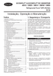
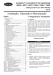
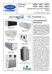
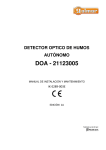
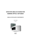
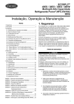
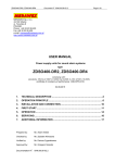
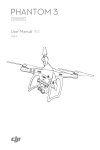
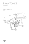
 IGNIS 2000 CONVENTIONAL FIRE DETECTION AND ALARM SYSTEM IGNIS 2040 FIRE DETECTION AND ALARM CONTROL PANEL Operation and Maintenance Documentation ID‐E339‐001GB I Edition 2 ID‐E339‐001GB The IGNIS 2040 conventional fire detection and alarm control panel covered by the present manual complies with the requirements of the following European Union Directives: CPD 89/106/EWG on construction materials; EMC 2004/108/WE on electromagnetic compatibility LVD 2006/95/WE on low‐voltage electric equipment. The IGNIS 2040 control panel has been approved with the EC‐Certificate of Conformity No. 1438/CPD/0243 issued by the Scientific and Research Centre for Fire Protection (CNBOP) Józefów, Poland, an EU notified authority No. 1438, confirming its compliance with the requirements of PN‐EN 54‐2:2002+A1:2007 standard. The device has been also approved with the Allowance Certificate No. 1131/2011 issued by CNBOP. The certificate may be downloaded from www.polon‐alfa.pl web site. 1438 Polon‐Alfa Spółka z ograniczoną odpowiedzialnością Sp. k. 155, Glinki Street, PL 85‐861 Bydgoszcz, POLAND 11 1438/CPD/0243 EN 54‐2:1997+A1:2006 The IGNIS 2040 fire detection and alarm control panel Conventional, for indoor use Provided options: ‐ fire alarming devices output ‐ output signal delays ‐ interdependent alarming ‐ testing mode ‐ alarm counter and additional functions, inputs and outputs: see technical data contained in ID‐E339‐001GB manual Read the manual carefully before the detector assembling and commissioning. Any nonconformity with the instructions contained in the manual may be harmful or may cause violation of the law in force POLON‐ALFA bears no responsibility for any damage resulting from usage inconsistent with the manual. A waste product, unsuitable for further use, shall be passed to a waste electric and electronic equipment collection point. NOTE: The manufacturer reserves the right to change specifications of products at any time without prior notice. ID‐E339‐001GB 3 CONTENTS 1 INTRODUCTION .............................................................................................................. 4
1.1 DOCUMENTATION CONTENTS ..................................................................................................................... 4
1.2 CONTROL PANEL APPLICATION .................................................................................................................... 4
1.3 SAFETY CONDITIONS .................................................................................................................................... 4
1.3.1 Electric shock protection ..................................................................................................................... 4
1.3.2 Installation and equipment safety ....................................................................................................... 4
1.3.3 Repairs and maintenance .................................................................................................................... 4
1.3.4 Fuse replacement ................................................................................................................................ 5
1.4 DEFINITIONS ................................................................................................................................................ 5
2 DEVICE COMPLETENESS .................................................................................................. 5
3 TECHNICAL SPECIFICATIONS ........................................................................................... 6
4 DESIGN DESCRIPTIONS ................................................................................................... 7
4.1 GENERAL CHARACTERISTICS ........................................................................................................................ 7
4.2 OVERALL DIAGRAM ..................................................................................................................................... 8
4.3 CONTROL PANEL GENERAL DESCRIPTION .................................................................................................... 8
4.4 CONTROL PANEL GENERAL OPERATION PRINCIPLE ..................................................................................... 9
4.5 MODULE ARRANGEMENT ............................................................................................................................ 9
4.6 HANDLING AND SIGNALLING ELEMENTS ................................................................................................... 10
4.7 CONTROL PANEL FUNCTIONS AND ACCESS LEVELS ................................................................................... 13
4.8 LCD INDICATIONS, FUNCTIONS APPLICATION ........................................................................................... 14
4.9 EVENT MEMORY ........................................................................................................................................ 16
5 CONTROL PANEL OPERATION MODES .......................................................................... 17
5.1 QUIESCENT MODE ..................................................................................................................................... 17
5.2 ALARM MODE ............................................................................................................................................ 17
5.2.1 Fire alarm signalling............................................................................................................................. 17
5.2.2 Fire alarm verification by the attending personnel ............................................................................. 17
5.2.3 Automatic alarm signal verification .................................................................................................... 18
5.3 FAULT MODE ............................................................................................................................................... 18
5.4 DISABLEMENT MODE ................................................................................................................................. 19
5.5 TESTING MODE .......................................................................................................................................... 19
6 POWER SUPPLY ............................................................................................................ 19
6.1. BASIC POWER SUPPLY ............................................................................................................................... 19
6.2. RESERVE POWER SUPPLY .......................................................................................................................... 19
6.2.1 Automatic power supply switch‐off .................................................................................................. 20
7 INSTALLATION .............................................................................................................. 20
7.1 CONTROL PANEL MOUNTING .................................................................................................................... 20
7.2 WIRING ...................................................................................................................................................... 20
8 CONTROL PANEL SPECIAL APPLICATIONS ..................................................................... 21
8.1 EXPLOSION ENDANGERED PREMISES PROTECTION .................................................................................. 21
9 INPUT AND OUTPUT CIRCUIT CONNECTING TERMINALS .............................................. 22
10 MAINTENANCE ........................................................................................................... 23
10.1 GENERAL RULES ....................................................................................................................................... 23
10.2 PERIODICAL TESTING ............................................................................................................................... 23
10.3 FUSE REPLACEMENT ................................................................................................................................ 24
11 PACKING, STORAGE AND TRANSPORTATION ............................................................... 24
12 CONTROL PANEL COMMISSIONING INSTRUCTIONS AND PROPER OPERATION CHECKING AFTER INSTALLATION ................................................................................ 25
APPENDIX A ...................................................................................................................... 27
4 ID‐E339‐001GB 1 INTRODUCTION 1.1 DOCUMENTATION CONTENTS The purpose of this Operation and Maintenance Documentation (OMD) is to present the application, design and operation of the IGNIS 2040 fire detection and alarm control panel which constitute a part of the fire detection and alarm system. The documentation contains necessary information on the IGNIS 2040 control panels for designers, fitters and maintenance technicians. Together with the User Manual IO‐E339‐001, intended for those who are on duty directly at the control panel, it makes the complete operating documentation attached to the control panel and delivered to its user. 1.2 CONTROL PANEL APPLICATION The IGNIS 2040 fire control panel is designed to: 1. signal a fire occurrence detected by an interoperating fire warning devices (automatic and manual), 2. indicate a fire endangered place by identification of the alarming detection line , 3. actuate fire protection equipment, 4. transmit a fire signal to proper services, e.g. Fire Brigades. The IGNIS 2040 control panel is intended for continuous operation in premises of low dust level at ambient temperature from ‐ 5 °C to + 40 °C and air relative humidity up to 80 % at +40 °C. 1.3 SAFETY CONDITIONS 1.3.1 Electric shock protection The POLON 4000 system fire control panels are ranked as the 1st protection class devices and can be used only in the case of application of additional protection against electric shocks, such as zeroing or protective grounding. 230 V/50 Hz mains supply circuits insulation is reinforced and resists 2800 V voltage test; low‐voltage circuits (below 42 V) insulation is able to resist test voltage of 700 V DC. 1.3.2 Installation and equipment safety Wire installation should be made using conductors of the required fire resistance and should be properly protected in passages through fire zone boundaries. In order to avoid undesirable interaction, a required distance between the low‐voltage installation and a power installation and a lightning protection system should be maintained. From the system electromagnetic interference immunity, it is recommended to utilise protective grounding. Reserve power supply batteries should be connected to the panel at the final stage of the installation. The panel components are heat sensitive. The maximum ambient temperature should not exceed + 40 °C. The space left around the device should be big enough to secure free air flow. Air humidity in the premises where the panel operates should not exceed 95 %. 1.3.3 Repairs and maintenance Maintenance works and periodic inspections should be executed by skilled personnel employed by companies authorised or trained by Polon‐Alfa. Any repairs must be carried out by the manufacturer. Polon‐Alfa bears no responsibility for the operation of any apparatus being serviced or repaired by unauthorised personnel. ID‐E339‐001GB 5 1.3.4 Fuse replacement In the event of fuse replacement, an equivalent fuse replacement should be used: of the appropriate type and nominal value. The appropriate types and nominal values are contained in table 2.3. 1.4 DEFINITIONS Conventional detection line A two‐core line with non‐addressable detectors installed in, terminated with an end‐of‐line resistor. Fire warning device An element installed in detection lines triggering a fire alarm, e.g. a fire detector, manual call point. Line number A consecutive number from the 1 ÷ 6 range, which is assigned to the control panel outputs where detection lines are connected to. Zone A separated part of a supervised facility that specific warning devices forming one detection line are allocated to. Standard configuration A set of data saved in the control panel memory defining default parameters set by the manufacturer, such as delay times, disablements, alarm variants, etc. Quiescent (supervision) mode An operation mode, in which the control panel is power supplied from an electric energy source that meets the settled requirements, during which no other operation mode is indicated. Alarm (fire) mode An operation mode the control panel triggers after receipt and verification of a fire occurrence signal from fire warning devices. Disablement mode An operation mode, in which it is deliberately blocked the control panel ability to receive signals from any fire warning devices and to evoke alarms, or the control panel output and/or transmission path to any fire detection and alarm system component that is a part of alarm circuit. Testing mode An operation mode in which the control panel indicates functioning checking. Fault mode An operation mode in which the control panel indicates a fault of anything in alarm installation or its own circuits. 2 DEVICE COMPLETENESS Table 2.1 lists the set of items which compose the IGNIS 2040 control panel furnishings. Table 2.2 specifies auxiliary equipment that can be installed in the IGNIS 2040 control panels. This equipment should be ordered separately. Table 2.3 contains a list of the fuses used in the control panel. Table 2.1 Item
1
2
3
4
5
Description
IGNIS 2040 fire detection and alarm control panel Operation and Maintenance Documentation (OMD)
Servicing manual
Warranty certificate
Control panel unit package
Quantity
1 1 1 1 1 6 ID‐E339‐001GB Table 2.2 Item
1 2 3 4 5 6 Description
12 V/3.2 Ah ÷7 Ah battery Fire detectors Detector bases Manual call points WZ‐31 additional indicator Signalling devices Remarks
two pcs required for control panel according to Appendix A acc. to particular detector manual according to Appendix A according to offer Table 2.3 Item
1 2 3 Part description
Quantity
1 pc 1 pc 1 pc F1 melt fuse F630L250 F2 melt fuse F500L250 F3 melt fuse T3,15L250 3 TECHNICAL SPECIFICATIONS GENERAL PARAMETERS Overall dimensions L x H x G Mass (without batteries) Ingress protection Operation temperature range Allowable operation relative humidity Transportation temperature range POWER SUPPLY Basic power supply: − mains voltage − max. power draw from mains Reserve power supply: − 2 batteries, dim.: 151/65/98 (L/W/H) − reserve power supply time − battery charging current, max. − maximum battery internal resistance (together with connecting cables and clamps) Battery current consumption: − in quiescent mode, at max. line load − in alarm mode, max. External devices power supply voltage Admissible current draw from external devices power supply output, max. DETECTION LINES Number of detection lines Detection line resistance, max. Number of detectors installed in a detection line, max. Number of manual call points in a detection line, max. 311 x 337 x 81 mm < 4kg IP 30 ‐5 °C ÷ +40 °C 95 % at +40 °C ‐25 °C ÷ +55 °C 230 V + 10 % ‐ 15 % 50 Hz 0.5 A 2 x 12 V/7 Ah (optionally 3.2 Ah, 5 Ah) 72 h 0.6 A 2 Ω 55 mA 500 mA 24 V= ±15 % 400 mA 4 ÷ 6 (depending on configuration) 2 x 100 Ω 32 10 ID‐E339‐001GB Number of beam smoke detectors (DOP) a line, max. End‐of‐line resistor in a detection line Allowable quiescent current of warning devices in a detection line Detection lines insulation resistance INPUTS/OUTPUTS Number of external signalling devices lines Allowable signalling devices lines resistance Signalling devices line operation voltage Allowable L5 signalling devices line current, max. Allowable L6 signalling devices line current, max. Relay outputs: general fault fire alarm programmable relays USB connector ALARMING OPTIONS Fire alarm types Alarm variants Alarm transmission delay time EVENT MEMORY Memory capacity Event time record accuracy Readout methods 7 1 (without an end‐of‐line resistor) 10 kΩ ±5% 1.6 mA 100 kΩ 2 (replaceable with detection lines 5 and 6) 10 % of signalling devices resistance, but not more than 100Ω 24V= ±15 % 180 mA 180 mA 1 A / 30 V (NO or NC) – 1 pc. 1 A / 30 V (NO or NC) – 1 pc. 1 A / 30 V (NO or NC) – 6 pcs for interoperation with PC computer 1st stage alarm 2nd stage alarm one‐stage alarm two‐stage alarm with output signal delay preliminary reset interdependent alarming 0÷10 min (programmable with 5‐s jump) 999 events 1 s on LCD display or in PC computer after data transfer through USB connector 4 DESIGN DESCRIPTIONS 4.1 GENERAL CHARACTERISTICS 9 microprocessor‐based control 9 LCD to display user messages 9 event memory 9 date and time display 9 USB connector to interoperate with PC computer 9 interoperation with Polon‐Alfa 30 and 40 model range conventional detectors 9 up to 6 detection lines 9 up to 2 alarm lines 9 8 relay outputs 9 24 V output for external devices power supply 9 programmable − alarm variants − 0 ÷ 10 min delays − relays 9 reserve power supply > 72 hours 9 approved to PN‐EN54 standard. 8 ID‐E339‐001GB 4.2 OVERALL DIAGRAM Fig. 1 Overall diagram 4.3 CONTROL PANEL GENERAL DESCRIPTION The control panel is intended for wall mounting. The front side is made in the form of a metal cover plate with a rectangular window in which all handling and signalling elements are located as well as a liquid crystal display. The cover plate can be removed after unfastening 4 screws. Cable bushings are located in the casing upper part and they are intended to introduce alarm installation wires and mains power supply conductors. Some space is also provided there to place spare cables. The ID‐E339‐001GB 9 following elements are located inside the cabinet on the printed board edge: wire connectors, restart push button, battery connection push button, configuration jumpers and USB port of the event recorder. The control panel general view and dimensions are shown in Fig. 4. 4.4 CONTROL PANEL GENERAL OPERATION PRINCIPLE The IGNIS 2040 is a conventional (non‐addressable) control panel that interoperates with fire detectors installed in two‐core detection lines terminated with end‐of‐line resistors. The device indicates a fire alarm or fault with a detection line accuracy. The control panel processor continuously analyses all necessary information received from the detection lines, monitors handling element status, controls optical and acoustic signalling and controls output circuit relays. It supervises the basic and reserve power supply circuits advising possible faults. 4.5 MODULE ARRANGEMENT The IGNIS 2040 control panel module arrangement is shown on Fig. 2. 1.
2.
3.
4.
5.
6.
7.
8.
9.
10.
11.
12.
13.
14.
15.
Connection clamps for installation conductor screens. Example of detection line wire introduction and connection. Example of power supply line wire connection. Relay outputs connector (detachable from the board). Detection lines connector (detachable from the board). External devices 24 V power supply connector. Configuration jumpers: • S1…S8 – relay contacts configuration as closed or open, • S9, S10 – L5 and L6 lines function setting as detection or alarm line, • S11 – earth fault monitoring disconnection, • S12 – input filters connection with casing. USB connector. S15 jumper – default (factory) access codes restoration. ‘Restart’ push button. ‘wł. aku’ push button – restart of the control panel power supplied by battery cluster only. 24 V reserve power supply connector (battery cluster 2 x 12 V). Potentiometer to adjust the battery buffering voltage. Slot to insert a list of fire zone descriptions. Control panel cover plate. F1 – Battery circuit fuse ‐ 630mA F. F2 – External devices power supply circuit fuse ‐ 500mA F. F3 – Mains power supply fuse ‐ 3,15A T. Fig.2 Control panel subassemblies arrangement 4.6 HANDLING AND SIGNALLING ELEMENTS The push buttons, indicators (LCD diodes) placed on the control panel front plate are executed in the form of a flexible foil keypad as shown in Fig. 3. The push buttons and indicators functions are described in Table 4.1. IK‐E339‐001E 11 Fig. 3 Handling and signalling elements Table 4.1 Ite
m Description 1 Element 2 Red diode Yellow diode Push button Yellow diode 3 Push button 4 Yellow diode Push button 5 (WYŁĄCZENIE OPOŹNIENIA) Yellow diode Push Function General fire alarm signalling with distinction: • 1st stage fire alarm by flashing light, • 2nd stage fire alarm by steady light Control panel fault mode signalling Number and description of current faults display on LCD (‘quick’ access to function F.01 FAULTS READOUT) Control panel fault disablement mode signalling Displaying disablements detailed information on LCD (‘quick’ access to function F.03 DISABLEMENTS). Testing mode signalling Displaying the function enabling the control panel testing on/off (‘quick’ access to function F.04 HARDWARE TESTING) Indication of reset of T1 and T2 delay times for actuation of the alarming outputs (no delays) Delay disablement (switch off) – T1, T2 times reset 12 IK‐E283‐001E button Yellow diode 6 Indication of disablement of alarm signalling devices installed in L5 or L6 lines: • by flashing light – disablement of one line (L5 or L6),if both were configured as alarm lines • by steady light – disablement of all signalling devices (both L5 and L6 alarm lines, or one alarm lines if only one was configured as alarm line Push button Disablement/ re‐enablement of signalling devices installed in L5 or L6 line 7 Push button In the alarm mode: • acknowledgement of receipt of fire alarm by personnel and the control panel internal acoustic signalling device silencing • change of alarm outputs activation delay time intended for fire danger recognition from T1 to T2 (in the case of the two‐stage alarm variant)) In the fault mode: • fault acknowledgement and the control panel internal acoustic signalling device silencing 8 Push button Reset of alarm mode of the control panel and detectors in detection lines 9 Zone field Indication of alarm mode of the zone (line) No. 1, 2, 3, 4, 5, 6 Red • the first zone where the alarm mode occurred is diodes signalled by flashing light, afterwards by steady light • zone fields enable text description of the fire zone (from the bottom: a slot to insert a label with description) 10 Green diode Indication of the control panel operation powered from 230 V/50 Hz mains or reserve battery; 11 Yellow diode Program memory fault, RAM memory fault or configuration fault signalling. 12 13 LCD display Displaying the information as per description in p. 4.8 Push button Main push button for the control panel menu handling. • ‘short’ pressing < 1 s – entering the submenu one level down, • ‘long’ pressing > 1 s – return to the submenu one level up. Push buttons Push buttons for function selection, ‘scrolling’ events or faults, selected parameter change. Push buttons Parameter selection push buttons (moving cursor to the left‐right) 14 /delay re‐enablement (switch on)– return to settled T1, T2 times IK‐E339‐001E 13 4.7 CONTROL PANEL FUNCTIONS AND ACCESS LEVELS Four access levels to handling elements are provided in the control panel: 1st access level intended for the persons who take first measures after a fire or fault signal occurrence. At this access level, the ACKNOWLEDGEMENT (17), FAULT (2) and DELAY RESET (5) push buttons are active, as well as an access code entering function. 2nd access level is provided for persons holding special responsibility for safety who are trained and authorised to service the control panel within a limited scope. The second access level is obtainable by appropriate access code entering. It allows to use all the push buttons located on the device’s front panel and functions that do not change the control panel programmed configuration. 3rd access level is designed for trained persons who are authorised to change the configuration data and carry out maintenance works. The 3rd access level is obtained by proper access code entering. 4th access level is provided for persons trained and authorised by the manufacturer to change the factory software and use the service functions. The access level is reachable by appropriate access code entering. Default access codes: •
•
•
2nd access level – 2 0 0 3rd access level – 3 0 0 4th access level – 4 0 0 The default access codes can be changed to the user’s codes with the help of the F.11 function. Note! The default access codes restoring can be executed by closing the 1‐2 contacts of the S15 jumper located on the printed board. Table 4.2 presents the functions that are available at the control panel menu after relevant code entering. Table 4.2 Function Function name No. Access level required for this function F.01 FAULT READOUT 1st or 2nd, or 3rd, or 4th F.02 DISABLEMENTS 2nd or 3rd, or 4th F.03 HARDWARE TESTING 2nd or 3rd, or 4th F.04 EVENT READOUT 2nd or 3rd, or 4th F.05 STANDARD CONFIGURATION 3rd or 4th F.06 LINE CONFIGURATION 3rd or 4th F.07 RELAY PROGRAMMING 3rd or 4th F.08 DELAY SETTING 3rd or 4th F.09 EVENT MEMORY RESET 4th 14 IK‐E283‐001E F.10 DIAGNOSTICS FUNCTIONS 4th F.11 ACCESS CODE CHANGE 4th F.12 DATE AND TIME SETTING 4th 4.8 LCD INDICATIONS, FUNCTIONS APPLICATION The IGNIS 2040 control panel is equipped with an alphanumeric 2 x 20 characters liquid crystal display (LCD) that enables configuration parameters setting and readout of information on the control panel status. During the control panel normal operation, in the quiescent mode, the LCD displays the date and time. The remaining functions are supported by a menu that enables a particular function selection after appropriate access code loading in accordance with Table 4.3. Any movement within the menu is possible using the ENTER push button. A short pressing results in a submenu opening. The submenu leaving and entering one level up is performed by a longer (> 1 s) pressing of the same push button. Table 4.3 Function name (LCD display) FAULTS READOUT F.01 Enter Description Readout of current faults detected by the control panel Function recall – push button short pressing Exit – longer than 1 s pressing FAULTS QUANTITY: 03 01. Line 2 break – Quantity of all faults (e.g.03). – Fault number (e.g. 01); fault name DISABLEMENT F.02 Enter Faults review with the push buttons Disablement of detection (alarm) line or relay output Function recall – push button short pressing Exit – push button longer than 1 s pressing – 1..6 – detection (alarm) line number – 1..8 – relay number Lines: 1 2 3 4 5 6 PK: 1 2 3 4 5 6 7 8 Selection of line number or relay number in order to its disablement or re‐enablement – using push buttons Disablement – setting 0 with the help of push buttons instead of line/relay number. Re‐enablement – setting line number 1...6 or relay number 1…8. HARDWARE TESTING Testing of control panel diodes, acoustic signalling device and detection F.03 Enter lines Function recall – push button short pressing Exit – push button longer than 1 s pressing Diodes test: OFF – OFF – diodes test (LEDs) disabled Test of Line: 0 0 0 0 0 – 0 0 0 0 0 0 – line 1..6 testing disabled. Test selection with push buttons Enablement of front panel diodes and internal sounder testing by changing ON instead of OFF with push buttons Enablement of detection line testing by setting line number 1..6 instead EVENTS REAOUT F.04 Enter 184. L1 alarm reset 2011‐01‐05 15:20:44 IK‐E339‐001E 15 of 0 with push buttons Readout of events recorded in control panel memory Function recall – push button short pressing Exit – push button longer than 1 s pressing – Event No. (e.g. 184); event name – Date and time of event occurrence STANDARD CONFIG. F.05 Enter Events review with push buttons. Latest recorded event has No. 1 Standard (default) configuration settings loading Function recall – push button short pressing Exit – push button longer than 1 s pressing STANDARD CONFIGUR.? – Load the standard configuration? NO – NO – no changes in configuration settings Attention! Entering YES with push button results in replacing all configuration settings with the standard (default) ones. LINE CONFIGURATION Detection (alarm) lines configuration settings F.06 Enter Function recall – push button short pressing Exit – push button longer than 1 s pressing L. 1 detection ON – line No. (e.g. 1); line type (e.g. detection); on/off Al.var. – 3 coinc. with – alarm variant No.; coincidence with a line (e.g. 2) Function enables setting of required line parameters: L. 1 – number of line being programmed ON – on/off (disablement) of line, Al.var. – alarm variant assignation: 0, 1 ,2, 3 coinc. with L 2 – means No. of line (e.g. 2) operating in coincidence with line being programmed – only for alarm variant 3. Selection of parameter to be changed – with push buttons, parameter change – with push buttons Note: 5 and 6 line type change from detection to alarm one possible only with the help of terminal block jumpers in quiescent mode. RELAY PROGRAMMING Relay actuation programming F.07 Enter Function recall – push button short pressing Exit – push button longer than 1 s pressing PK: 2 ON alarm 1 – PK No. (e.g. 2); on/off; PK actuating event (e.g. alarm 1 ) Lines: 0 2 0 0 0 0 – No. of line (e.g.2) that PK actuating event is connected with Function allows to allot to every relay 1..6 event that will evoke its actuation. ON ‐ on/off (disablement) of relay, Possible events: alarm 1 – zone 1st stage alarm, alarm 2 – zone 2nd stage alarm, alarm P – fire 2nd stage alarm (general), reset – relay connectors switchover for reset time. For events: alarm 1, alarm 2 it is necessary to settle line (zone) that will evoke relay actuation. Selection of parameter ‐ with push buttons Parameter change – with push buttons 16 IK‐E283‐001E DELAYS SETTING 2nd stage alarm delays setting F.08 Enter Function recall – push button short pressing Exit – push button longer than 1 s pressing Time for acknowl. T1 = – T1 ‐ delay of 2nd stage alarm without acknowledgement 2nd stage alarm delay – T2 ‐ delay of 2nd stage alarm with acknowledgement ’
Selection of T1 or T2 using push buttons Times being programmed with with 5‐s interval. (e.g. 2’30‐ means 2 min and 30 s) Note: T1 time for acknowledgement should be shorter than T2 time provided for alarm verification. EVENT MEMORY Event memory erasure ERASURE Function recall – push button short pressing F.09 Enter Exit – push button longer than 1 s pressing EVENTS ERASURE ? – Concerns events recorded in control panel memory. NO – NO – by default lack of event memory erasure. DIAGNOSTIC FUNCTIONS F.10 Enter Attention! Switching to YES with push button results in erasure of all events recorderd in control panel non‐volatile memory. Diagnostic functions (intended for factory service) Function recall – push button short pressing Exit – push button longer than 1 s pressing Software version: V1.0 – Information name ACCESS CODE CHANGE F.11 Enter Change of displayed information with push buttons Access code change Function recall – push button short pressing Exit – push button longer than 1 s pressing – Operation name – Access level No., 3‐digit code Access code change Level: 2 code: 0 0 DATE & TIME SETTING F.12 Enter CSP IGNIS 2040 2011‐01‐05 15:20:44 – Value being read out Note: Default codes restoration is done automatically – by closing 1‐2 contacts of S15 jumper located on printed board – Fig. 2 Date and time setting Function recall – push button short pressing Exit – push button longer than 1 s pressing – Copan name – Year ‐ month ‐ day hour : min : sec Selection of value being set ‐ with Setting – using push buttons. push buttons 4.9 EVENT MEMORY The software necessary for the event memory readout and information materials are available in Internet on the www.polon‐alfa.pl web site after obtaining an access code. Hardware requirements concerning PC computer: o accessible USB port; o hard disc of ca. 25 MB free memory; o installed Windows 98/ME/2000/XP/Vista/7 operating system IK‐E339‐001E 17 Before starting the program, the computer should be connected to the control panel with a typical USB cable ended with an A type USB plug (the computer’s end) and a B type plug (the control panel’s end). After detection of a new device connected to the USB port and the Ignis2win.exe program launching, the control panel and computer are ready for the event memory contents transmission. The transmission starts after the icon ‘event list download’ clicking. 5 CONTROL PANEL OPERATION MODES 5.1 QUIESCENT MODE In the quiescent mode, i.e. while the control panel is waiting for a signal from fire warning devices, only the green POWER (10) diode is lit on the front panel to inform that power supply is on. In addition, the current time and date are displayed on the LCD display (12). The general fire alarm relays and zone relays are inactive, and the general fault relay is in an active state (no fault). 5.2 ALARM MODE 5.2.1 Fire alarm signalling The following indications can be observed on the control panel front side during the fire alarm: at least one of the ZONE 1…6 zone indicating diodes is lit; the first zone where a fire has occurred is distinguished with flashing light, all others are lit with steady light; - the FIRE diode is lit with steady light – the 2nd stage fire alarm or with flashing light – the 1st stage fire alarm; - a fire alarm message, indicating the zone (or zones) number and the elapsing time remaining until fire alarm relays are activated (transmission), appear on the LCD; - an internal acoustic signalling device is switched on, with a 0.5 s/0.5 s interval signal - active alarm lines generate a signal that actuates external alarm devices. The control panel acoustic signal can be silenced at the 1st access level by pressing the ACKNOWLEDGEMENT push button. External devices can be disabled (or re‐enabled) after entering the 2nd level access code by the SIGNALLING DEVICES DISABLEMENT push button. -
5.2.2 Fire alarm verification by the attending personnel The control panel enables an occurrence verification by the personnel in case a fire alarm has been revealed. It is required that the attending person approaches the panel and confirms an alarm receipt within a programmed T1 time by pressing the ACKNOWLEDGEMENT push button. In case the person on duty fails to acknowledge the alarm receipt within the T1 time period, the control panel initiates an alarm transmission outside (e.g. to the monitoring centre or fire brigade) after the T1 time lapse or automatically actuates the fire‐fighting equipment (depending on the system configuration). After the fire alarm receipt acknowledgment, the person on duty is given an additional T2 time for recognition of a real fire threat in the premises. Both T1 and T2 times are programmable; the T2 time should be longer than the T1 time. The elapsing time left for the alarm acknowledgment and for the threat recognition by the person on duty is displayed on the LCD (5). In case a threat does not exist, the person should reset the alarm mode with the RESET push button. This operation is effective when no fire factor is present in the vicinity of the fire warning device that has evoked the alarm and after the 2nd access level is obtained by the code entering. 18 IK‐E283‐001E 5.2.3 Automatic alarm signal verification The control panel possesses algorithms that enable verification of fire alarm signal coming from fire warning devices. Recognition of the received signal as a fire alarm is preceded by multiple checking readout of the line status. Moreover, it is a possible to program the following alarm variants for every detection line: 1
2
3
4
One‐stage alarm – variant 0 without any delay, in which a line element actuation immediately triggers the 2nd stage fire alarm (the alarm transmission relays actuation). Two‐stage alarm – variant 1 two‐stage alarm with a programmable delay time T2 = 0…10 min for the 2nd stage fire alarm indication. Lack of the personnel acknowledgement shortens the delay time to the programmed T1 time; the RELAYS DISABLEMENT push button pressing will result in the delay time zeroing and immediate outputs actuation. One‐stage alarm with a preliminary reset, (type A dependence in accordance with PN standard) – variant 2 without any delay, in which the first detector actuation evokes its immediate reset. An alarm is triggered after a repeated activation of any detector in the same line before 60 s ± 10 s time lapse from the previous actuation. After 60 s ± 10 s time passing without any new alarm triggering, the control panel returns to the initial mode. One‐stage alarm with a line interdependence (coincidence), (type B dependence in accordance with PN standard) – variant 3 without any delay, in which it is possible to create pairs of interdependent zones. The first alarm evoked in a line belonging to an interdependent pair actuates only the internal acoustic buzzer, zone field indication and LCD signalling (without the general fire indicator actuation). The 2nd stage fire alarm is triggered immediately after entering the alarm mode by the other line belonging to the interdependent pair under a condition that the first alarm has not been reset. The first alarm lasts until its manual reset. 5.3 FAULT MODE The fault mode is signalled by the control panel by the yellow FAULT (2) diode and by an acoustic fault signal. The acoustic fault signal is an interrupted sound in 0.5 s/0.5 s cycle. Detailed information about a fault type is available on the LCD display after the F.01 FAULT READOUT function selection or after the FAULT (2) push button pressing at the 1st access level. The control panel fault mode is signalled in case of: - a break of or a short circuit in any detection line; - a break of or a short circuit in alarm (external acoustic signalling device) line; - a mains power supply fault; - a battery fault resulting from its internal resistance increase above 2 Ω or a lack of a battery; - a battery charging device fault; - a break in the charging circuit; - a F1 fuse insert burn‐out; - a microprocessor system fault; - an earth fault, i.e. connection of any control panel circuit or any line attached to it with the control panel metal casing or with other grounded objects. Silencing of the sound signal is possible at the 1st access level by pressing the ACKNOWLEDGEMENT push button. A reset of light signalling proceeds automatically after the fault removal. The only exception is a kind of system fault resulting from the microprocessor controller serious fault, which cannot be silenced, due to its importance, with the ACKNOWLEDGEMENT push button. A system fault resulting from false configuration data can be silenced with the ACKNOWLEDGEMENT push button but in such the case it is necessary to check the control panel configuration settings and, eventually, correct them. If the signalling still persists, after such checking/correcting, it means that IK‐E339‐001E 19 the control panel is damaged. It is necessary to switch the control panel power supply off and call the service personnel. In the fault mode, the PK8 general fault relay is released. 5.4 DISABLEMENT MODE The disablement mode is signalled by the control panel by the yellow DISABLEMENT (3) diode. Any disablement and re‐enablement (and the disabled outputs readout) is possible after entering at least 2nd access level code and with the DISABLEMENT (3) quick access push button or using the F.03 DISABLEMENT function. The disablement concerns all inputs/outputs/L1 ÷ L6 line outputs and PK1 ÷ PK8 relay outputs. The disabled detection lines are inactive, they do not report any fault or alarm, and relay and alarm outputs are switched off. The yellow DISABLEMENT (3) diode stops the disablement mode indication when all disablements are removed. 5.5 TESTING MODE The control panel allows for testing fire warning devices in detection lines by actuating them with e.g. fire factor imitators. Switching a zone (line) into the testing mode is possible after entering at least 2nd access level code. Testing is executed utilising the F.04 HARDWARE TESTING function, which is available immediately after pressing the TESTING push button. During the testing mode, the control panel does not indicate a fire alarm and does not actuates any outputs linked with it. The test alarm indication is limited to the red diode flashes in the zone field of the number consistent with the detection line being tested. The signalling duration time is equal to several seconds, it begins at the moment when a test alarm is reported by the detector and control panel and is finished with an automatic reset. The F.04 HARDWARE TESTING function enables also an efficiency inspection of all diodes located on the control panel front side and internal acoustic signalling device. In general, the testing mode is indicated by the TESTING (4) diode when at least one line is switched over into the testing mode. 6 POWER SUPPLY 6.1. BASIC POWER SUPPLY The control panel basic power supply source is 230 V/50 Hz mains. A voltage alteration within +10 % and ‐15 % range does not influence the control panel proper operation. The control panel internal power supply device has the general current efficiency at 1.5 A, which is used for the control panel and charging circuits power supply; 0.4 A load is reserved for auxiliary external devices. 6.2. RESERVE POWER SUPPLY In case of mains voltage outage, the control panel is supplied from a reserve battery cluster of 24 V nominal voltage and 3.2 ÷ 7 Ah capacity. A switch‐over from the main power supply to the reserve one is carried out automatically, without any break in power supply. The approximate control panel operation time when it is supplied from the batteries only at the full lines load (in the quiescent mode and + 0.5 h in the alarm mode), with no current draw from the external device power supply output, is presented in Table 6.1 for various battery capacities. Table 6.1 Battery capacity Approximate control panel operation time 3.2 Ah 47 hours 20 IK‐E283‐001E 5 Ah 76 hours 7 Ah 108 hours (25% ageing decrease in the batteries capacity has been considered) During the control panel configuration, when some current consumption by auxiliary external devices is considered (especially during the quiescent mode), it is important to take into consideration that the reserve battery powered device operation time will be accordingly shorter. The battery cluster is automatically charged by the control panel power supply device. The efficiency of both the batteries and charging device is continuously monitored and any fault is being signalled. The battery is recognised as inoperative when its internal resistance (together with the connection resistance) increases and exceeds 2 Ω. The battery installation, operation and waste‐disposal must be carried out pursuant to the manufacturer’s manual. A waste battery must be delivered to a proper collecting and recycling point in accordance with the law in force. 6.2.1 Automatic power supply switch‐off During the control panel operation, being powered only from the battery cluster, the battery voltage progressively decreases. A reserve power supply voltage drop down to ca. 22 V is acoustically signalled. Further decline in the battery panel voltage and achieving ca. 21 V level will result in the control panel automatic switch‐off. The power supply renewed switch‐on, after a properly charged battery re‐connection, may require pressing of the WŁ.AKU push button which is located inside the control panel on the printed circuit board. 7 INSTALLATION 7.1 CONTROL PANEL MOUNTING The control panel should to be mounted on a wall using three expansion anchor bolts of minimum diameter at 8 mm. The spacing of the fastening bolt holes is shown in Fig. 4. The control panel mounting is possible only without batteries. 7.2 WIRING Detection, alarm and controlling lines should be routed according to the commonly applicable principles used in telecommunications. The lines must be continuous and terminated with end‐of‐
line resistors. They can be routed alongside high voltage electrical conductors. The detection line wires can be inserted into the control panel from the installation led in the wall plaster. They are introduced into the control panel upper part through round bushings: separately the mains supply wires and low‐voltage wires. The terminals of the detection lines and relay outputs on the printed circuit board are removable what enables easy wire connection. The connection terminals arrangement and descriptions is presented in Fig.2. IK‐E339‐001E 21 Fig.4 Control panel dimensions and fixing opening arrangement The 230 V/50 Hz mains conductors must be fastened to the mains power supply terminals – Fig.2, paying attention to careful conductor fixing that precludes accidental touching of bold conductor endings. The control panel can be used only in the case of application of additional protection against electric shocks, such as zeroing or protective grounding. Laboratory tests, checking the required by the standards in force interference immunity, have been carried out with grounding application. 8 CONTROL PANEL SPECIAL APPLICATIONS 8.1 EXPLOSION ENDANGERED PREMISES PROTECTION Installation of fire detectors and manual call points in zones where explosive mixtures of gases and liquid vapours occur is possible in intrinsically safe detection circuits. Such circuits provide the [Ex Ib IIC] safety category. Intrinsically safe detection lines in the IGNIS 2000 system can be created in conventional lines with an application of intrinsically safe separators. Detailed information concerning the device installation in explosion endangered areas is available at the intrinsically safe element manufacturers. 22 IK‐E283‐001E 9 INPUT AND OUTPUT CIRCUIT CONNECTING TERMINALS The control panel is equipped with a set of connecting terminals designed for connection of alarm installation wires, external devices and mains power supply. The terminals enable connection of wires of a maximum diameter at 1.2 mm and a cross section at 1.5 mm2. It is recommended to use screened conductors approved by appropriate certification authorities. The arrangement of the terminals with their marking is presented in Fig. 2. Mains power supply: The cable terminals (with the F3 fuse) are provided to connect 230 V/ 50 Hz mains wires and a protection wire – item 3 in Fig. 2. Detection lines: The detection lines should be connected to the 4…6 pairs of connectors with properly marked polarisation. The line 5 and 6 can be configured as a detection or alarm one depending on the S9 and S10 jumpers position in accordance with the information contained in Fig.1. The S9 and S10 jumpers position is detected in the quiescent mode. It is recommended to create detection lines using a screened cable certified by an appropriate authority, e.g. in Poland – with YnTKSY ekw 1 x 2 x 0.8 cable certified by the CNBOP. The terminals to connect the cable screens are placed above the detection line terminals on the control panel cabinet near the bushings ‐ Fig. 2. The detection lines should be terminated with 10 kΩ end‐of‐line resistors. Fig. 5 depicts the method of G‐
40 base connection in a detection line. In the case of unused lines, the end‐of‐line resistor is connected to the control panel output terminals. All supervised lines must be furnished with an end‐
of‐line resistor – otherwise the control panel will report a fault. Alarm (controlling) lines. Lines 5 and 6 can be used as alarm lines under a condition that the S9 and S10 jumpers are set in position 2‐3 as shown in Fig. 1. The lines are monitored (as for a break and short circuit) and designed mainly to connect external acoustic devices. They can be also used for fire‐fighting equipment control. To ensure proper monitoring and controlling of the connected signalling devices or other equipment, the total line resistance should range from 130 Ω to 10 kΩ. In the case of an unused line or control of a device of higher resistance, it is obligatory to connect in parallel a 10 kΩ end‐of‐line resistor. A diagram showing a detection line connection is presented in Fig.1. In the quiescent mode, a monitoring voltage is observed in the controlling lines, with polarisation consistent with the marking shown in Fig. 1 – the diodes connected in series with the signalling devices are polarised in such a way to block the current flow. In the active state (alarm mode) the voltage polarisation is changed for the opposite one and the diodes connected to the signalling devices are in the conducting state. Fire alarm relay outputs: The relay outputs, activated during a fire alarm, are designed to control additional protecting devices or to transfer information about the control panel mode to the monitoring centre. The control panel is equipped with relays marked as PK1÷PK8, their terminals are connected to the terminal board. Fig. 1 (and the informative label inside the control panel) depicts the terminal position in the non‐potential state (the control panel not power supplied). PK1÷PK6 –programmable relays assigned by default to the detection lines in such the way that the L1÷L6 line alarm mode actuates the PK1÷PK6 relays accordingly. It is possible to program every PK1÷PK6 relay in dependence on any detection line (zone) alarm mode or the general fault occurrence. In the case of detectors that require a break in the power supply circuit for the alarm mode reset, it is provided to program any PK1÷PK6 relay in such the way that the terminals are switched over for the time of the control panel alarm mode reset (see F.08 RELAY PROGRAMMING). PK7 – general alarm relay, switches the terminals over at the moment of a 2nd stage fire alarm occurrence, what can be program delays by 0..10 min. Using the DELAY DISABLEMENT (5) it is possible to disable (switch off) the delay function and obtain immediate actuation. IK‐E339‐001E 23 PK8 – general fault relay. During the control panel normal operation the relay is switched on. It switches over at the moment when a fault or voltage decrease occurs. A typical application of the relay is the fault signal transmission to the monitoring centre. External device power supply output: Two pairs of terminals supplying 24 V DC voltage are located on the terminal board and they are designed for power supply of the external devices that are activated e.g. from relay outputs. The positive terminal is protected with a 500 mA monitored melt fuse. NOTE: In case external devices draw current also during quiescent mode, the operation time of the control panel which is supplied from internal batteries during a mains (basic) power supply outage, will decrease proportionally to the current consumption from the control panel. Signal transmission. Auxiliary devices controlling. The control panel is able to control protecting devices or transfer fire alarm signals to a monitoring station using the relay outputs that are activated during the fire alarm. The relays operation may be disabled with the help of the F.03 DISABLEMENT function when it is necessary. The zone relays can be programmed for actuation dependent on various occurrences and zones, using the F.08 RELAY PROGRAMMING function. All relays are furnished with a possibility to switch the contacts over for opened and closed (NO or NC) with the help of jumpers. 10 MAINTENANCE 10.1 GENERAL RULES Fire alarm systems, as safety installations, must be continuously kept at full efficiency, therefore they require proper maintenance. The premises user is obliged to ensure the installation maintenance, best of all by signing an appropriate agreement with a maintenance technician. The maintenance consists in carrying out periodical inspections and removal of possible faults. The maintenance technician should thoroughly study this manual. He should know exactly the operating principles of the control panel and interoperating manual and automatic fire warning devices, as well as other devices connected to the control panel. It is highly recommended to pass a training organized by the manufacturer that covers fire alarm systems application, installation and operation. The maintenance technician should also know the premises territory, displacement of the system, detection line routes, arrangement of fire detectors and manual call points, and environmental conditions that may influence the devices work. 10.2 PERIODICAL TESTING The periodical checks consist in operation tests of all detectors and fire manual call points installed in the detection lines, the control panel and its output circuits: the lines that control external acoustic signalling devices or fire‐fighting devices, as well as the protecting device monitoring line and the monitoring system circuits. The periodical tests should be executed in accordance PKN‐CEN/TS 54‐14: 2006 standard. Periodical testing frequency: the manufacturer recommends executing the periodical tests at least once per year. Nevertheless, the system owner, in agreement with the system designer and the maintenance technician, should increase the test frequency, if the system operating conditions are hard (high humidity, corrosion environment, dusting, etc.). The periodical testing scope consists in: - event memory readout (using a computer), in order to check the control panel attending personnel appropriate work and possible signals indicated by the control panel; - inspection (testing) of every signalling diode and acoustic signalling device of the control panel; 24 IK‐E283‐001E -
-
-
consecutive testing of every fire detector (e.g. using smoke and heat imitators) and manual call points installed in every detection line , utilising a possibility to switch any line for testing; visual evaluation of the fire detectors technical condition (level of dirt, corrosion, permanent soil) and of manual call points, especially in case of their longer operation, that should be carried out during a device testing; if necessary, cleaning of the fire detectors and their replacement or regeneration; checking the external signalling devices and connected protective and fire‐fighting devices under a condition that the premises user is informed and taking necessary measures to avoid panic or any damage in the building resulting from the test execution. The external signal receivers and a monitoring centre must be notified of a planned test; battery voltage value checking on the clamps during buffering – proper voltage value amounts to 27.1…27.6 V; battery condition checking – according to the battery manufacturer recommendations. 10.3 FUSE REPLACEMENT The control panel is equipped with three melt fuses in the following circuits: - battery cluster – F1 melt fuse of F630L250 type; - external devices power supply – F2 melt fuse of F500L250 type; - mains power supply – F3 melt fuse of T3,15L250 type. The fuses are accessible after the control panel cover plate removal; their arrangement is shown in Fig. 2. 11 PACKING, STORAGE AND TRANSPORTATION Packaging The control panel is placed in a unit packing, reducing free movement possibility and eliminating damage occurrence during loading and transportation. The following data are marked on the package: ‐ the name or the trade mark of the manufacturer; ‐ the name and the type of the control panel; Moreover, the following marking is placed on the package: “CAUTION FRAGILE”, “UPPER SIDE, DON’T TURN OVER”, “KEEP DRY” or equivalent marks according to the PN‐85/0‐79252 Polish Standard. Storage The control panel should be stored in closed premises at a temperature between + 5 oC and + 40 oC and relative humidity not exceeding 80 %, free of corrosive vapours and gases. In case the control panel is stored for a longer period, it is necessary to connect it to a power supply for at least 1 hour and execute operation tests every 6 months. During storage the control panel should not be exposed to heat radiation: direct sun light or heating devices. Transportation The control panels should be carried in their packing by closed transport means, taking into consideration the transport recommendations marked on the package, and protecting them against sharp shocks and avoiding ambient temperature exceeding the – 25 oC to + 55 oC range. IK‐E339‐001E 25 12 CONTROL PANEL COMMISSIONING INSTRUCTIONS AND PROPER OPERATION CHECKING AFTER INSTALLATION The operations to be done before the control panel commissioning: • detection, alarm, power supply lines preparation in accordance with the design; • installation of devices in the detection and alarm lines; • removal of the mains F3 fuse insert from the control panel terminal block; • the control panel assembly; • connection to appropriate terminal of all lines introduced to the control panel, with exception of 230 V mains conductors; • creation of the paper insert with zone descriptions (and its location in the zone field on the front panel) • preparation of the line elements list with their location description. Electric connections inspection: • checking of the configuration jumpers positions on the control panel printed circuit board; • checking of correctness of line wires connection to the control panel terminals with special attention to proper polarization (‘+’, ‘‐‘) • inspection of end‐of‐line resistors connection in the last bases of the supervised lines (detection and alarm ones); • in the case of unused lines (detection and alarm ones) – checking of end‐of‐line resistors connection in the lines terminals in the control panel; • batteries insertion; • connecting in series two 12 V batteries with special attention given to ‘+’, ‘‐‘ polarisation marking on the battery clamps. Commissioning • connection of the mains voltage and the PE wire. ATTENTION! Dangerous voltage! • The control panel commissioning by inserting the F3 mains supply fuse insert; • readout of the faults revealed by the control panel and removal of possible discrepancies in the circuits; • the control panel optimal configuration parameters setting using the functions described in Table 4.3; • testing optical indicators on front panel; • testing all line elements (detectors, MCP, signalling devices and other equipment connected to the system) paying attention to their real location consistence with the description in the zone field; • checking operation of the executive devices interoperating with the control panel • testing alarm and fault signal transmission; • modification of the default access codes for the user codes (if necessary). After the installation commissioning it is advised to check and possibly to set the current date and time and the event memory erasure. The works can be treated as finished when all actions described above have been performed and proper operation of all system devices has been confirmed as well as the control panel operation in the quiescent mode (without faults and disablements signalling) – the installation can be passed to its user. 26 IK‐E283‐001E Fig. 5 G‐40 base connection way into detection line Note: The detailed information concerning the G‐40 base is provided in the IK‐E287‐001E manual. IK‐E339‐001E 27 APPENDIX A IGNIS 1000 SYSTEM LINE ELEMENTS Element description Quiescent current 1) 40 model range conventional detectors DOR‐40 Optical smoke detector 60 µA DUR‐40 Universal optical smoke detector 60 µA TUP‐40 Heat detector 40 µA DOT‐40 Multi‐sensor smoke and heat detector 150 µA DOP‐40 Beam smoke detector 5.0 A 2) TOP‐40 Multi‐sensor heat and flame detector 90 µA 30 model range conventional detectors PUO‐35 Flame detector 100 µA Intrinsically safe detectors DUR‐40Ex Universal optical smoke detector 60 µA PUO‐35Ex Flame detector 100 µA TUN‐38Ex Universal heat detector (no base needed) 100 µA Manual call points ROP‐63 Manual call point 0 µA ROP‐63H Manual call point 0 µA Multisystem elements 5.0 A 2) DOP‐6001 Beam smoke detector 1)
‐ maximum current drawn from a detector line 2) ‐ when the jumpers set in accordance with the DOP‐40, DOP‐6001 manual. Only one detector per line, without end‐of‐line resistor ID‐339‐001GB/02.2012/05.2012