1
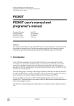
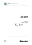
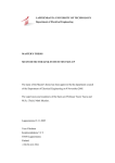
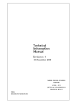
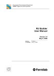
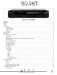
CMS NOTE 2007/---
Available on CMS information server
August 5, 2007
CMS Beam Scintillator Counter VME Readout
A.J. Bell, R.J Knegjens
*
University of Canterbury, Christchurch, New Zealand
M.M Hashimoto
Auckland University, Auckland, New Zealand
R. Hall-Wilton, V. Ryjov
CERN, Geneva, Switzerland
On Behalf of the CMS Beam Radiation Monitoring Group
Abstract
The early development of the BSC VME readout is presented; including an overview of the hardware and
software setup and the current status of the data acquisition system. The VME modules used in the hardware
setup are the CAEN V2718 optical link bridge, V812 constant fraction discriminator and the V767 TDC. The
software package HAL is used to interface with the VME modules. The C++ code that handles this
communication is detailed, as are the installation of HAL and the CAEN VME drivers. Various acquisition
modes of the TDC produce unstable outputs, and an investigation into these is also described.
* Principle Author. Contact [email protected]
1
Introduction
In the early commissioning phase of the LHC, it will be vitally important to be able to monitor the conditions of
the p-p beams as they enter the very forward regions of the CMS cavern.
It is to be expected that interactions between the proton beam and residual beam-pipe gas and interactions with
the beam-pipe itself prior to its entry in to the underground experimental cavern (UXC) will produce
unacceptable quantities of beam halo muons until the control of the LHC is fully understood. Misalignment of
the CMS endcaps will also produce scattering of particles during the early stages of operation.
The Beam Scintillation Counter (BSC) is being designed in order to monitor the particle rates and times over the
entirety of the LHC bunch train. The BSC consists of 36 individual channels (18 channels per end) comprising
of scintillator detector tiles mounted on the front faces of the Hadron Forward calorimeters (HF) and the
CASTOR tables and read out via PM tubes. The output from these PM tubes will be sent to a VME readout
system for the purpose of extracting timing information from the ‘hits’ on each channel.
By appending a time tag to the hits it will be possible to construct plots and histograms detailing the bunch
structure, halo muon rates and their directions, and the z-vertex position to aid in the commissioning of the LHC
in the CMS experiment regional.[1]
The VME readout will employ discriminator and TDC modules controlled via an Optical PCI-VME bridge†.
The TDC can operate in one of four possible modes. Three of these modes, Continuous Storage, Start Trigger
Matching and Stop Trigger Matching, warranted further investigation as to their usefulness for the BSC readout.
It was desired to ascertain the time resolution, data output size, and maximum input rate and reliability of each of
these modes.
This internal note summarizes the work done by Robert Knegjens as part of a CERN summer student project on
behalf of NZCMS and funded by the NERF and TEC New Zealand agencies.
2
2.1
VME Readout System Overview
Hardware Setup
The aim of the BSC VME readout system is to provide timing and shape measurements of incoming
photomultipliers (PM) tube signals using TDC and ADC VME modules respectively. The system receives input
signals from the PM tubes either directly or after they have been split by a NIM PM amplifier [1]. The signals
are then fed into a CAEN V812 constant fraction discriminator and a CAEN V1721 ADC. The discriminator
converts the signals into ECL format and passes them to a CAEN V767 TDC. Once measurements have been
made, the TDC and ADC modules send their data to a Dell PowerEdge 2950 Rack PC using the CAEN V2718
PCI-VME optical link bridge. The setup is shown in figure 1, and the technical specifications of each VME
module are given in section 2.2.
† A fast ADC is also to be implemented in to the design to monitor pulse shapes of some selected channels.
2
Figure 1. Block diagram of the BSC VME readout
The TDC makes timing measurements of the hit signals with respect to the beam orbit marker. The various
acquisition modes that the TDC can be run in are discussed in Section 5. The purpose of the ADC is to generate
digital representations of the raw PMT hit signals. The ADC is currently on order, and hence has not yet been
integrated into the BSC VME readout setup.
2.2
2.2.1
VME Modules
CAEN V2718 PCI-VME Optical Link Bridge
The V2718 is a VME master module, which can be controlled by a standard PC equipped with the PCI controller
card (CAEN Module A2818). The communication between the V2718 and the PCI card takes place through an
optical fiber cable. The V2718 can perform all the cycles foreseen by the VME64. Table 1 details the technical
specifications from the V2718 Manual [2].
VME – CAEN V2718 Optical Link Bridge
Packaging
6U high, 1U wide VME unit
PC Interface
Optical Link
Transfer Rate
70Mbytes/s
VME Interface
A16/A24/A32, VME64x complaint
Table 1. Technical specifications of the CAEN V2718 VME Module
2.2.2
CAEN V812 Constant Fraction Discriminator
The V812 is a VME module housing a 16 channel constant fraction discriminator. The module accepts 16
negative inputs and generates precise ECL pulses when the input signals exceed a given threshold. The constant
fraction technique allows to precisely determine the timing of the discrimination. Table 2 details the technical
specifications from the V812 Manual [3].
3
VME – CAEN V812 Constant Fraction Discriminator
Packaging
6U high, 1U wide VME unit
Inputs
16 inputs (negative polarity, 50 Ohm impedance)
Max input voltage
-5 V
Min detectable signal
-5 mV
Threshold range
-1 mV to -255 mV (1 mV step)
Constant fraction
20%
Delay
Selectable in 4 ns steps (20 ns full scale)
Outputs
16 ECL outputs with a fan-out of two
Input/output delay
Set delay + 4.5 ns
Output width
Programmable from 15 ns to 250 ns
Dead Time
Programmable from 150 ns to 2 µs (±10%)
Max outputs time walk
±400 ps for input signals in the range from -50 mV to - 5 V
with 25 ns rise time
VME Interface
A24/A32
Table 2. Technical specifications of the CAEN V812 VME Module
The V812 constant fraction discriminator (CFD) should reduce the amount of time jitter of the signals passed to
the TDC. Unlike standard discriminators which produce a logic output only when the amplitude of the input
signal crosses a preset threshold, a CFD uses an algorithm that determines when the input signal voltage
surpasses a fixed fraction of its own peak amplitude (fig 2 and fig 3). This in effect gives a well defined output
trigger time which is independent of the input pulse height.
Fig 2 Standard discriminator trigger time (t) based
on a preset input threshold
Fig 3 The CFD bases its output trigger on a fixed
percentage of the input peak amplitude. As the signals
produced from scintillators have roughly equal rise
times, this results in a more defined trigger time, t.
4
The V812 uses a fixed fraction level of 20%. The user can still define the input level threshold to reject signals
below a chosen amplitude, as with the standard discriminator module. The difference with the CFD is that these
thresholds do not correspond to the actual level that triggers the discriminator outputs, this being a “constant
fraction” of the input signals.
Figure 4 shows the principle of operation of the CFD technique. The delayed input signal is summed with an
inverted, attenuated signal. The amount of delay is adjustable from 4ns – 20ns in 4ns steps using onboard
jumpers. The resulting signal is fed to a comparator which gives an output at the zero-crossing of the input. For
correct operation the maximum of the attenuated pulse has to cross the delayed pulse at the selected fraction.
Figure 4. Functional diagram of the CFD technique.
The improved definition of the trigger time from the CFD, however, comes at the expense of channel dead time
as a certain amount of signal delays and processing are required. In the V812 module, this dead time has a
minimum value of 150ns (150ns to 2µs programmable).
2.2.3
CAEN V767 TDC
The V767 is a VME module which houses 128 independent time-to-digital conversion channels. The module
hosts 4 deadtimeless TDC chips developed at CERN by the ECP-MIC Group. The module is a General Purpose,
20 bit dynamic range TDC and allows COMMON START operations with typical bin size of 0.78 ns LSB. The
module is programmed via an on-board microcontroller by using a set of high-level symbolic commands, so
enhancing the friendliness of the unit and its flexibility to match a large variety of experimental conditions
(Trigger Matching, Continuous Storage and COMMON STOP emulation). Table 3 details the technical
specifications from the V767 Manual [4].
5
VME – CAEN V767 TDC
Packaging
6U high, 1U wide VME unit
Dynamic range
20 bit
LSB
0.78 ns
Double hit resolution
10 ns
Input channels, Start
Differential ECL level, 110 Ohm impedance
min. FWHM 10 ns
Trigger, Reset, Busy, Clock, Drdy
Differential ECL level, 110 Ohm impedance
Min FWHM 25 ns
Local buffer
FIFO 32K (TDC to FIFO tranf. rate = 20 MHz)
Clock source
Internal (40 or 60 MHz) / External
Trigger window
From 1 clock cycle to full dynamic range
VME Interface
A24/A32
Table 3. Technical specifications of the CAEN V767 VME Module
2.2.4
CAEN V1721 ADC
The V1721 is a VME module housing a 8 Channel 8 bit 500 MS/s Flash ADC Waveform Digitizer with
threshold Auto-Trigger capabilities. The single ended analog input signal has a dynamic range of 1Vpp. The DC
offset of the signal can be adjusted channel per channel by means of a programmable 16bit DAC. The VME
interface is VME64X compliant and the data readout can be performed in Single Data Transfer (D32), 32/64 bit
Block Transfer (BLT, MBLT, 2eVME, 2eSST) and 32/64 bit Chained Block Transfer (CBLT). Table 4 details
the technical specifications from the V1721 Manual [5].
VME – CAEN V1721 ADC
Packaging
6U high, 1U wide VME unit
Analog Input
8 channels, single ended or differential
Input Range
1Vpp
Bandwidth
250MHz
Sampling Rate
10 to 500MS/s simultaneously on each channel
Memory buffer
2 million samples per channel
Trigger
Common Ext trig (NIM or TTL) and VME
VME Interface
VME64x complaint
Table 4. Technical specifications of the CAEN V1721 VME Module
Note: The V1721 ADC is still on order and has not been integrated into the BSC readout system.
6
2.3
Rack PC Software Setup
The CAEN V2718 Optical Bridge VME Module is connected via an optical link to the CAEN A2818 PCI
controller placed in the Dell Rack PC. The Rack PC is running 32-bit Scientific Linux 4 and has CAEN Version
2.5-4 drivers, headers and libraries installed (see Chapter 3 for installation instructions).
The BSC readout makes use of the software package HAL (Hardware Access Library) [6] to interface with the
CAEN V2718 bridge. HAL acts as a layer between a hardware device driver (in this case the CAEN drivers) and
a user program, allowing user-friendly, robust and manageable access to the device through the use of a bus
adapter and address tables (see Section 4). Figure 5 shows a block diagram of the HAL functionality (taken from
the HAL user manual [7]).
Figure 5. Functional block diagram of HAL[7]. Dashed arrows indicate optional information flow.
The c++ programs used to control the various VME modules have all been written using HAL, which has
simplified our efforts greatly.
3
3.1
Software Installation
Scientific Linux 4 (32-bit)
The Rack PC being used for the VME Readout was originally installed with 64-bit Scientific Linux 4 (SLC4).
However, problems were encountered when trying to compile the HAL software package with the SLC4 64-bit
libraries. Since HAL has only been tested on 32-bit machines or 64-bit machines running in 32-bit mode, the
decision was made to replace the 64-bit installation on the Rack PC with a 32-bit SLC4 installation.‡
‡ A possible solution for successfully installing HAL on a 64-bit SLC4 is to compile all objects that are in shared 64-bit
libraries with the ‘-fPIC’ (Position Independent Code) compiler flag. This approach was not attempted, as the relevant shared
libraries were not well enough understood (setting –fPIC as a global compiler flag is not recommended).
7
The installation of 32-bit SLC4 onto the Dell PowerEdge 2950 Rack PC is straight forward. A step-by-step
installation guide can be found online at the CERN IT webpage [8].
Notes:
-
Although both MAC addresses of the Rack PC were registered with the CERN IT department during
installation, only ‘eth1’ could find the install image on the LinuxSoft server during the NFS setup.
-
In the Network Configuration screen, the computer hostname was manually set to ‘PCCMSBRM9’ and
DHCP was selected for the IP/Netmask of both ‘eth0’ and ‘eth1’.
-
The disk was partitioned using LVM Volume Groups, including a single ‘ext3’ partition for all mount
points (i.e. /root, /home etc.) and a ‘swap’ partition of 2GB.
3.2
CAEN Drivers
The BSC Readout uses the CAEN V2718 Optical Bridge. Drivers and installation instructions for the CAEN
VME Bridges can be found online [9]. The V2718 drivers were installed from the source rpm file ‘xdaqcaenvme-SLC4-2.5-4.src.rpm’. These drivers need HAL version 3.17 or higher.
Brief Installation instructions:
As root/superuser run:
rpmbuild --rebuild xdaq-caenvme- SLC4-2.5-4.src.rpm
This places three binary RPMs in the directory /usr/src/redhat/RPMS/i386. Install the RPM’s containing the
library, include files, firmware upgrade utility and the driver (the debug rpm can be ignored) by running:
rpm –ivh xdaq-caenvme-{version-release}.i386.rpm
{version-release}.i386.rpm
kernel-module-xdaq-caenvme-
The library is installed in /usr/local/lib/libCAENVME*. The include files are installed in /usr/local/include. A
service named ‘caenvme’ is created in /etc/init.d. To have the service automatically loaded at every system boot;
as root/superuser run:
/sbin/chkconfig --add caenvme
To run the service without having to reboot; as root/superuser run:
/sbin/service caenvme start
3.3
Hardware Access Library (HAL)
HAL version 3.19 was installed for the VME readout system. The software download, user manual (which
includes installation instructions) and API can all be found at the official HAL website [6]. No problems were
encountered in installing HAL using the instructions from the user manual.
Notes:
-
The HAL User Manual gives outdated directory locations for the installed CAEN hardware drivers.
The CAEN drivers should be installed in the locations given in the previous section (as they are by
default for an RPM installation); this is where the HAL installation configure file will look.
-
HAL was compiled without XDAQ installed, as XDAQ currently has no SLC4 support.
-
HAL was installed in the directory /opt/hal.
8
4
VME Control with HAL
4.1
Address Tables
For HAL to communicate with a VME module, it must have a custom address table for the given module that
details the relevant registers. Specifically, each register of interest must have a name, address modifier, width,
the address offset from the module’s base address, a mask and state specifying if the register is capable of
read/write. The HAL User Manual gives examples and details of the ASCII address table format, which is used
in the BSC VME readout. The less obvious entries of the HAL address table are the address modifier (AM),
width and mask. AM specifies the data access mode for the module, and has been set to 09 (extended user data
access) for all the CAEN VME modules in the BSC readout. The ‘width’ is the width in bytes of the item in
memory (usually 2 or 4). To select only specific bits from an address register, a logical AND is performed with
the ‘mask’ to set all non-interesting bits of the register to 0.
As every VME module requires a custom address table, it was necessary to write from scratch address tables for
the CAEN V812 and V258B discriminators. For the CAEN V767 TDC a reasonably complete address table
written by HCAL already existed, and only a handful of items were added. The reference manual of any given
module should contain the register information needed to construct the HAL address table.
4.2
Discriminator Control Code
The c++ code written to control the CAEN V812 constant fraction discriminator (and later also the V258B
discriminator) was based on the HAL example code for a TTCvi module with a dummy VME bus adapter
(/opt/hal/examples). The example code provides the user with a command prompt to read/write to registers in the
address table, print the address table for reference and handle sequences. Obvious changes to the example code
are loading the real CAEN bus adapter, loading the correct address table and setting the correct base address for
the module (corresponding to the rotary switches housed on the board). Other changes include better error
handling of the command prompt.
Overall, this simple code is sufficient to provide full control of the VME discriminators in the testing stage.
Sequences allow for more automated control of the discriminators, and it is foreseen that a program that deals
purely with these sequences will replace the current code in the later stages of the BSC VME design. The
discriminators should even be simple enough to be fully integrated into the main function of the TDC.
Notes:
-
The HAL example code Makefile references the Makefile (and Makefile.in) at the HAL base directory.
It is therefore necessary to write a Makefile from scratch when copying the example code, and hence
carefully linking to the numerous locations of the HAL and CAEN headers and libraries.
-
Remember to export to LD_LIBRARY_PATH the HAL library locations before the compiled code is
executed.
4.2.1
Sequences
A sequence is a list of stored commands that can be executed by the user at will, providing easy initialization of
the hardware. With sequences it is also possible to declare variables and have conditional ‘goto’ commands. The
use and format of sequences are described with examples in the HAL User Manual [7]. The discriminator control
code uses the PersistentCommandSequencer object to handle sequences, which is detailed in the HAL API [10].
In the BSC readout, the sequences written for the discriminators sets the pattern inhibit, channel thresholds and
output widths for the various different modes of the TDC.
4.3
TDC Control Code
Initial communication with the CAEN V767 TDC was successfully made using c++ code that reads/writes to all
registers of interest using a command prompt - similar to that used to control the discriminators. However, the
TDC is designed to be used with predefined opcodes that are written to its onboard microcontroller. Hence, code
that reads/writes to individual registers on command is not suitable. Additional code was needed to write
opcodes and to read and write operands to the opcode register, as well as ideally, automate the whole data
9
acquisition process.
Fortunately, the CMS HCAL group had already written some of this code for the V767 TDC. Most notably, they
wrote a CAENV767 object that handles opcode operations and defines function calls for key opcodes and
register settings. This CAENV767 object implements a VMEDeviceBundle, which is a wrapper for the
HAL::VMEDevice and HAL::VMEAddressTable objects (i.e. all communication with the TDC is still
done through HAL). The CAENV767 object has been edited for the BSC readout to include some additional
functionality, such as function calls that can read the error status and error code (via JTAG) of each TDC chip,
allow a soft (permanent) reset of the TDC to be set and allow configurations of the TDC to be loaded and saved.
In later code the VMEDeviceBundle has been discarded, and the CAENV767 directly implements the
HAL::VMEDevice object.
The BSC readout code for the V767 has been refined a number of times. The original code consists of a main
function that constructs a CAENV767 object and prompts the user for the TDC data acquisition mode (see
Section 5) and the duration (in seconds) they wish to run the mode for. The TDC is then setup with a series of
function calls to the CAENV767 object. The exception to these function calls is the code used to read from the
TDC output buffer, which is done directly with HAL commands in the ‘main’ function to keep things simple.
While in an acquisition mode, the program prints to screen at one second intervals the last received data event (in
the case of the trigger matching modes) or start time with subsequent hits (in the case of continuous mode), and
discards the data not arriving at these print intervals (after reading them from the data buffer so as not to have it
overflow).
The latest BSC TDC readout code contains separate programs for the continuous storage and start trigger
matching acquisition modes (stop trigger was dropped due to its poor time resolution of one clock cycle). The
‘main’ function of these programs takes as its first parameter the runtime of the mode in seconds. Both the TDC
and discriminator are created as objects in this code, and the discriminator is setup by running a sequence file at
startup (see Section 4.2.1). The CAENV767 object now directly implements the HAL VMEDevice rather than
the VMEDeviceBundle written by HCAL. All of the data that is read from the output buffer during the
acquisition is written into an output file, DAQ_output.txt. As before, data is also printed to screen at one
second intervals.
4.3.1
The Output Buffer
The TDC output buffer contains the output data organized into 32-bit words. If the TDC is running in Stop
Trigger Matching, Start Trigger Matching or Start Gating modes the data in the buffer is organized into ‘events’
with the following structure:
-
a ‘header’ that contains the event number value
-
the ‘data words’ (or datum) that contain the 20-bit converted time values
-
a ‘End Of block’ (EOB) word that contains the number of data words and a Status bit that is 1 or 0 if
the TDC chips have an error or no error respectively.
If the TDC is running in Continuous Storage mode then there are no header or EOB words.
For any given mode, if a read access is performed to the buffer when it is empty, a Non Valid Datum will be
read out. See figure 6 for the complete data structure. See the Appendix for an example of code used to read
from the buffer.
10
Figure 6. V767 Output Buffer Data Structure [4].
4.3.2
Error Checking
The V767 has a number of status registers and opcodes to provide for error checking. Some of these were
already included as function calls in the CAENV767 object and the others have been added since. Notably,
status register 2 [4, §3.17] provides single bit registers that go high for a global TDC error (an error on any TDC
chip), an individual TDC chip error (specifying which one of the four) or when the output buffer is full. It is also
possible to read the error code of a given TDC chip using a JTAG opcode. The 16-bit word that is returned is
shown in figure 7.
Figure 7. The error code of an internal TDC chip
The ‘Not Locked’ error refers to the Delayed Locked Loop (DLL) of the chip not having time to lock after a
reset. The ‘Hit Error’ normally implies that a hit has come in and been damaged due to the DLL not being
locked. Further explanations of these errors can be found in the TDC chip manual [11].
5
5.1
5.1.3
TDC Acquisition Modes
Continuous Mode
Description
In continuous storage mode all HIT signals from the enabled channels and all START signals are stored as data
words on the local buffer of the TDC (the concept of an ‘event’ is meaningless – see Sections 5.2 and 5.3)
11
The stored data can be either an absolute time measurement (relative to the last RESET or subsequent clock
overflows) or a relative time measurement referred to the last received START signal.
Figure 8. Continuous Storage Sequence [4 §1.2.4]
Figure 8 gives an example of a sequence of START and HIT signals that would be stored in the output buffer as:
DATUM 1
START time(1)
DATUM 2
HIT time(1)
DATUM 3
HIT time(2)
DATUM 4
START time(2)
DATUM 5
HIT time(3)
DATUM 6
HIT time(4)
DATUM 7
HIT time(5)
5.1.2
Setup
The TDC is setup to run continuous storage mode by a sequence of functions calls to the CAENV767 object:
reset()
Resets the front-end of the module, then sleeps for 2 seconds. A
permanent reset can be set and cleared with setResetMode() and
clearResetMode() respectively.
modeContinuousStorage()
Puts the TDC into continuous storage mode.
setDRnotEmpty()
Sets the Data Ready mode of the TDC to ‘not empty’, which means
the Data Ready bit will go high when the output buffer has anything
on it. The state of the Data Ready bit is continuously checked with the
function call isDataReady(). Continuous mode also supports a Data
Ready mode of ‘almost full’ (set by the function call
setDRalmostFull()) which checks if the buffer has reached the ‘almost
full’ level set by the user. It is not possible to operate continuous
storage mode in ‘event ready’ mode, as the concept of an event is
meaningless.
enableStartTimeSubtraction()
If enabled, all HIT times are given relative to the last START time to
arrive before them. START times are given as absolute times relative
to the last reset or clock overflow.
useFallingEdgeStart()
Determines that the falling edge of the START signal is used for its
time measurement. Similarly useRisingEdgeStart() does the contrary.
useFallingEdge()
Determines that the falling edge of the HIT signals are used for their
time measurements. Similarly useRisingEdge() does the contrary.
enableAllChannels()
Enables all 128 input channels of the TDC.
disableAllChannels() will disable all 128 channels.
enableChannel(n)
Enable the nth input channel of the TDC. Similarly disableChannel(n)
will disable the nth input channel.
globalClear()
Clears the TDCs and output buffer. Resets the readout controller and
event counter. This function should be called before acquisition starts.
12
Similarly
5.1.3
Results
The Continuous Storage mode was the most appropriate and error free of the acquisition modes investigated. It
provides 1ns resolution accuracy and does not record hits within a predefined time window, allowing for
acquisitions across the entire 89µs orbit and using a clock synchronized to the orbit marker as the start pulse.
However, errors in the acquisition did occur on a regular basis and warranted further investigation as explained
in section 5.4.
5.2
Stop Trigger Mode
5.2.1
Description
In Stop Trigger Matching mode data is organized into a group of HIT signals called an ‘event’ (see Section
****). The event consists of all the HIT signals received from the enabled channels within a programmable time
window relative to the common TRIGGER signal. The stored data can be either an absolute time measurement
(relative to the last RESET or subsequent clock overflows) or a relative time measurement referred to the
beginning of the TRIGGER window.
Figure 9. Stop Trigger Matching Sequence [4 §1.2.1]
Figure 9 gives an example of a sequence HIT signals relative to a TRIGGER windows that would be stored in
the output buffer as:
HEADER
event 0
DATUM 1
HIT time(4)
DATUM 2
HIT time(5)
DATUM 3
HIT time(6)
DATUM 4
HIT time(7)
DATUM 5
HIT time(8)
EOB
num. of data read = 5
5.2.2
Setup
The TDC is setup to run stop trigger matching mode by a sequence of functions calls to the CAENV767 object:
reset()
Resets the front-end of the module, then sleeps for 2 seconds. A
permanent reset can be set and cleared with setResetMode() and
clearResetMode() respectively.
modeStopTrigger()
Puts the TDC into Stop Trigger Matching mode.
setDRevent ()
Sets the Data Ready mode of the TDC to ‘event’, which means the
Data Ready bit will go high when the output buffer has a complete
event (a group of hits with header and EOB words). The state of the
Data Ready bit is continuously checked with the function call
isDataReady().
enableTriggerTimeSubtraction() If enabled, all HIT times are given relative to the last TRIGGER time
13
to arrive before them.
useRisingEdge()
Determines that the rising edge of the HIT signals are used for their
time measurements. Similarly useFallingEdge() does the contrary.
setWindowWidth(X)
Sets the width of the trigger matching window in clock cycles (25 ns).
setWindowsOffset(X)
Set the offset of the trigger matching window in clock cycles (25 ns).
For a negative offset use hexadecimal numbers as the function expects
and unsigned int. For example, for a -100 clock cycle offset, enter
0xFFFF-100 = 0xFF9B. The offset + width must be less than 2000
[4 §4.5.3].
enableAllChannels()
Enables all 128 input channels of the TDC.
disableAllChannels() will disable all 128 channels.
enableChannel(n)
Enable the nth input channel of the TDC. Similarly disableChannel(n)
will disable the nth input channel.
globalClear()
Clears the TDCs and output buffer. Resets the readout controller and
event counter. This function should be called before acquisition starts.
5.2.3
Similarly
Results
The main issue with the Stop Trigger Matching acquisition mode is its poor time resolution, relative to the other
available modes. Whereas these other modes are accurate within 1/32 of a clock pulse (0.8ns), Stop Trigger
Matching has an intrinsic time resolution of one clock pulse (25ns). A workaround incorporating an additional
pulse in to a second channel input and subtracting its time from the hit channel can be implemented to reduce
this resolution. However, this would be at the cost of increased uncertainty of readout time due to the combined
uncertainties of the additional and original channels.
This mode of operation also proved to be very error prone. At any input frequency, a TDC error was flagged
indicating a combination of Hit Errors, Event Buffer overflows and Lock Errors. The cause of these errors could
not be easily accounted for and this combined with the poor time resolution determined the fate of this mode as a
potential mode of operation in the BSC readout.
5.3
5.3.1
Start Trigger Mode
Description
In Stop Trigger Matching mode data is organized into a group of HIT signals called an ‘event’ (see Section
4.3.1). It consists of the group of START signals that arrive within a time window (of programmable width and
relative position with respect to the common TRIGGER signal) and of the group of all HIT signals that reach the
enabled channels, relevant to the START signals within the same time window. The stored data can be either an
absolute time measurement (the zero time reference is represented by the RESET) or a relative time
measurement referred to the beginning of the TRIGGER Window for what concerns the START signals and
referred to the preceding START for what concerns the STOP signals.
Figure 10. Start Trigger Matching Sequence [4 §1.2.2]
14
Figure 10 gives an example of a sequence HIT signals relative to a TRIGGER windows that would be stored in
the output buffer as:
HEADER
event 0
DATUM 1
START time(2)
DATUM 2
HIT time(3)
DATUM 3
HIT time(4)
DATUM 4
HIT time(5)
DATUM 1
START time(3)
DATUM 5
HIT time(6)
DATUM 5
HIT time(7)
EOB
num. of data read = 7
5.3.2
Setup
The TDC is setup to start trigger matching mode by a sequence of functions calls to the CAENV767 object:
reset()
Resets the front-end of the module, then sleeps for 2 seconds. A
permanent reset can be set and cleared with setResetMode() and
clearResetMode() respectively.
modeStartTriggerTrigger()
Puts the TDC into Start Trigger Matching mode.
setDRevent()
Sets the Data Ready mode of the TDC to ‘event’, which means the
Data Ready bit will go high when the output buffer has a complete
event (a group of hits with header and EOB words). The state of the
Data Ready bit is continuously checked with the function call
isDataReady().
enableStartTimeSubtraction()
If enabled, all HIT times are given relative to the last START time to
arrive before them. START times are given as absolute times relative
to the last reset or clock overflow.
useRisingEdge()
Determines that the rising edge of the HIT signals are used for their
time measurements. Similarly useFallingEdge() does the contrary.
setWindowWidth(X)
Sets the width of the trigger matching window in clock cycles (25 ns).
setWindowsOffset(X)
Set the offset of the trigger matching window in clock cycles (25 ns).
For a negative offset use hexadecimal numbers as the function expects
and unsigned int. For example, for a -100 clock cycle offset, enter
0xFFFF-100 = 0xFF9B. The offset + width must be less than 2000.
enableAllChannels()
Enables all 128 input channels of the TDC.
disableAllChannels() will disable all 128 channels.
enableChannel(n)
Enable the nth input channel of the TDC. Similarly disableChannel(n)
will disable the nth input channel.
globalClear()
Clears the TDCs and output buffer. Resets the readout controller and
event counter. This function should be called before acquisition starts.
5.3.3
Similarly
Results
The start trigger mode gives a time resolution of 1ns, the same as Continuous mode. The use of an acquisition
window is also not desired as it would make the task of gathering hit information across the entire 89µs orbit
more difficult to achieve without inducing gaps in the timing. The start trigger mode also displayed nonsensical,
almost random errors, usually pertaining to buffer overflow errors in TDC ICs which were not receiving any
input.
15
5.4
Known Issues
All three modes tested showed varying frequencies of acquisition errors. There are four basic errors which can
occur to any one or more of the four TDC chips. These are Hit error, Event Buffer Overflow, Output Buffer
Overflow and Not Locked (signifying that the DLL circuit has lost synchronization).
The hit signals are fed into channels 0 and 1. The start signal input is a specialized input, common to all 4 TDCs.
Figure 11 shows the internal block diagram of the TDC ASIC. Each TDC chip has 32 input channels. TDC0
handles channels 0 through 31, TDC1 handles channels 32 through 63 etc, as shown in figure 12.
Figure 11. Internal block diagram of the TDC32 ASIC [11]
Figure 12. Block diagram of the CAEN V767 TDC module.
16
The investigation of the errors was done using the continuous mode operation. The reason this mode was chosen
was two-fold. Firstly, it is the only mode that does not require a set window width and window offset, thus
simplifying the search for the cause of the errors. Second, it was the most likely option for the final BSC readout
design.
A C++ program was written to test the acquisition and check for errors. The code takes an integer number of
seconds as its first argument which determines how long the acquisition would run for. On execution, the code
created the CAEN Bus Adapter, TDC and Discriminator objects, running a sequence script to set up the Pattern
Inhibit and Thresholds for the latter device. After successfully creating the objects, the TDC buffers were cleared
and the acquisition started.
As shown in figure 6, the meaning of the output buffer data is indicated by the state of 3 bits within the32 bit
output buffer register, namely bits 22 (Header), 23 (End of Block) and 24 (Start Bit). The code simply copies the
entire buffer in to a variable then evaluates a logical AND for each of the 3 bits to determine their values, and
hence the meaning of the data in the buffer. There are three possibilities of the meaning of the output buffer
data. The first is that the data is invalid, in which case the message “Invalid Datum” would be written to the
output file. The second is that there is a Start pulse. In this case, the absolute value of the clock (the time since
the readout) and the relative value of the clock (the time since the last data was readout) were written to the file.
The third case is that there is hit data on one or more of the channels. Here, the channel number(s) and time since
the start pulse was written to the output file. Every output buffer read was set to the output file in one of these
three forms. Additionally, a Start and Hit line was written to the screen every second.
An example of the output file is given below.
271
272
273
274
275
276
ABS: 501259
Ch 0
Ch 1
ABS: 601408
Ch 0
Ch 1
REL: 100149
TIME: 130ns
TIME: 850ns
REL: 100148
TIME: 130ns
TIME: 850ns
Lines 271 and 274 show the absolute clock value since the TDC was last reset and the relative time between
concurrent Start pulses. Here the input time period was 100µs and the relative time correctly shows 100,149 ns.
Lines 272, 273, 275 and 276 show the times at which a Hit signal arrived since the Start pulse and the input
channel on which it arrived. Again, the output correctly displays a 130ns time stamp for channel 0 and 850ns
time stamp for channel 1.
However, the output file also showed that the output buffer data is sometimes corrupt and Hit times and channels
were incorrect shown in lines 388 – 391.
384
385
386
387
388
389
390
391
ABS: 501259
Ch 0
Ch 1
ABS: 601408
Ch 26
Ch 27
Ch 28
Ch 29
REL: 100149
TIME: 130ns
TIME: 850ns
REL: 100148
TIME: 377ns
TIME: 377ns
TIME: 377ns
TIME: 377ns
The time of occurrence within an acquisition was random, as was the frequency of occurrence. In three
consecutive 30 second runs, no errors occurred. However, over 3000 errors occurred in the following run and
500 in the next! Longer and shorter time periods of the input waveform, shown in figure 13, were tried but all
gave the same behaviour. To attempt to cut down electrical noise induced in to the TDC from the neighboring
modules, the TDC was moved to various slots in the crate, using distance and the VME crate casing as shielding.
This too had no effect on the erroneous behaviour. Finally, increasing the times between the Start pulse and the
Hit pulses was tried. No difference in the frequency of output of the corrupt data was noted. It must be pointed
out that this erroneous data is not one of the 4 possible errors mentioned previously and in fact, there is no
method of differentiating these errors from ‘good’ data by using software. The question now is whether this
module can be trusted for the BSC readout and if the cause for the data corruption can be found.
17
Figure 13. Example TDC input waveform as seen from the discriminator OR output. The left hand pulse is the
Start pulse to the TDC (T = 0). The middle pulse is Hit 0 fed to Ch 0 (T + 150ns) of the TDC and the right hand
pulse is Hit 1 fed to Ch 1 (T + 800 ns) of the TDC.
The next step is to contact other CERN users of this TDC module to seek help from their experience and also to
contact CAEN with a detailed description of the experimental set up and errors.
5
Conclusion
Much progress has been made with the BSC readout system. It is now at a stage where communication between
the Linux PC and the VME hardware is achieved enabling further testing of the individual modules and their
operating modes. The software is running on 32 bit Scientific Linux 4 OS using HAL meaning that no further
development in that area is required. With this in place, the research in to the functions of the CAEN hardware
will be easier and the use of HAL will simplify the replacement of any of the modules during the development
stage and beyond.
Further testing of the V812 discriminator is required to determine its accuracy and whether any problems exist.
The TDC errors described in the previous section need to be rectified and this will be one of the major focuses
on the VME readout design in the immediate future.
In summary, the work carried out on the BSC VME readout system so far has been a huge step forward in the
development of the BSC project as a whole.
Acknowledgements
We would like to thank the following groups for their support:
The CMS HCAL group for the initial TDC code and the extensive help it provided
The CERN Electronics Systems Support team for their help and advice relating to the VME hardware
The Beam & Radiation Monitoring Group
P. Butler and J. Williams (University of Canterbury, New Zealand) for supplying TEC funding
D. Krofcheck (Auckland University, New Zealand) for supplying NERF grant funding
18
References
[1] BSC Design Note, A.J Bell et al, Awaiting submission as CMS Internal Note.
[2] V2718 Manual http://www.caen.it/nuclear/product.php?mod=V2718
[3] V812 Manual http://www.caen.it/nuclear/product.php?mod=V812
[4] V767 Manual http://www.caen.it/nuclear/product.php?mod=V767
[5] V1721 Manual http://www.caen.it/nuclear/product.php?mod=V1721
[6] Hardware Access Library Webpage: http://cmsdoc.cern.ch/~cschwick/software/documentation/HAL
[7] HAL User Manual
http://cmsdoc.cern.ch/~cschwick/software/documentation/HAL/manual/HALUsersGuide.pdf
HAL can be downloaded from ‘/distribution/hal-ver-03-19.tgz’. The user manual can be found at ‘. The
API can be found at ‘/generic/html/index.html’.
[8]
Scientific Linux 4 installation instructions: http://linux.web.cern.ch/linux/scientific4/docs/install.shtml
[9]
CAEN VME Bridge Drivers and Installation Instructions:
http://cmsdoc.cern.ch/~cschwick/VME/html/VMEBridges_CAEN.html
[10] The Generic API of the Hardware Access Library.
http://cmsdoc.cern.ch/~cschwick/software/documentation/HAL/generic/html/index.html
[11] 32 channel general purpose Time to Digital converter. J. Christiansen, CERN/ECP - MIC
19
Appendix
Output Buffer Example Code:
The output buffer can be emptied one word at a time by reading the relevant register in the address table via the
HAL::VMEDevice read command:
uint32_t data = 0;
tdc.read(“DataBuffer”,&data);
To check if the word is a ‘datum’, perform a logical AND with an appropriate mask (i.e. check to see if the
HEADER and EOB bits of the datum are both 0):
if( !(data&0x200000) && !(data&0x400000) )
printf(“This is a datum”);
Similarly, we can also check to see if a datum is a START signal, and then print its value in nano seconds (note
that the TDC has a resolution of 0.78 ns for its 40 MHz internal clock):
if( data&0x800000 )
printf(“START time: %f ns”,((double) (data&0xFFFFF)) * 0.78);
20