1
ATTACHMENT 2
Hard Wiring of Arrays
The method outlined in this procedure is to be followed if the interconnection between the solar modules
will be hard wired. It has been written to prevent a person being able to touch the two live array output
cables either within :
• a module junction box OR
• the isolator located near the array.
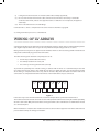
Double insulated positive and negative cables
Using this method, the junction boxes on the modules
will only have a live (nominal) supply of 12V or 24V
maximum.
DOUBLE POLE
ISOLATOR
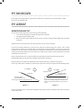
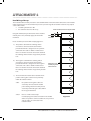
Please read this procedure while studying figure 2.1.
a) The positive cable from the isolating switch
or breaker is connected to the solar module
junction box which is designated as the positive
connection. This cable is double- insulated and
there are no other electrical connections between
the isolating switch and the array positive junction
box.
b) The negative cable from the isolating switch
or breaker is connected to the solar module
junction box which is designated as the negative
connection. This cable is double-insulated and
there are no other electrical connections between
the isolating switch and the array positive junction
box.
'MultiContact' style
insulated plug and
socket connector
c) To ensure that the installer does not work on live
positive and negative cables in close proximity
within the isolation switch:
either the positive and negative cables are
electrically connected to the double
pole isolating switch or breaker prior to
electrically terminating the cables within
the array junction boxes
and/or
there is a ‘multi-contact’ style
insulated plug and socket connection in the middle
of the array which is connected after the array is wired
and the cables are connected in the
isolation switch.
Figure 2.1
GRID-CONNECTED PV SYSTEMS • SYSTEM INSTALLATION GUIDELINES | 17