1
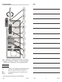
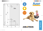
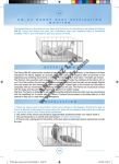
The GD-04K universal GSM
communicator and controller
The GD-04K is a universal GSM communicator. It controls and / or reports status of
different appliances remotely. Control can be performed by SMS instructions or dialling in.
The module is equipped with 2 power outputs with a status or pulse reaction. For status
monitoring the GD-04K module has four input terminals which react to grounding
(connecting to the GND terminal). Activation / deactivation of an input terminal can be
reported as an SMS, dialling in or a combination of both these options to up to 100
authorised telephone numbers. The GD-04K can also be supplemented by a GD-04A
backup battery which ensures powering the module when the mains is disconnected. The
module allows configuration using a PC with installed GD-Link 2.0.0 software (or higher)
locally via the USB cable or remotely. It can also be configured by programming SMS.
1.
Using the GD-04K
The GD-04K module uses four inputs (A – D) for SMS reporting (optionally dialling) to
predefined telephone numbers. It also offers 2 power relay outputs with options to control
them by pre-defined SMS commands or by dialling in according to the settings from
authorised numbers or from any (non-authorised) numbers.
Relay control:
by SMS instructions which can be independently pre-set for switching ON / OFF of
each relay output. Both relays can work in status or pulse mode, the mode is selectable
in the settings. If pulse mode is selected then based on activation command the output
will be switched for interval between 1 s to 10 hrs.
Dialling in. Both relays (X and Y) can be controlled by dialling in from a known
telephone number. Up to 100 numbers can be stored in the communicator. The GD04K doesn´t pick up an incoming call but verifies the caller’s telephone number. If the
caller’s telephone number is authorised, the call is rejected and the relay is activated /
deactivated as required (when the Impulse reaction is set then for predefined time).
Dialling in with limited use. While entering authorised telephone numbers the limit of
their use can also be defined for each of them. When the usage limit of a pre-defined
number is reached then any other calls are ignored. Reactivation can only be allowed
by an administrator (by SMS). This function is suitable as a subscription for entrance to
garages and so on.
Input status reporting:
Sending an SMS report when some of the inputs (A – D) are activated / deactivated
(connected or disconnected to / from GND). Each input has an option to edit the texts
which are reported. An SMS can be sent to all telephone numbers stored in the
communicator. For higher alert notice SMS report can also be followed by calling to the
numbers to which SMS reports have been sent.
Status monitoring. By the SMS command “STATUS”, the status of all inputs and
outputs can be checked when needed. This way is for example possible to check status
of connected devices which each status change is not required to report.
Caution: The GD-04K is not meant and is not certified as a security device to protect
premises.
GD-04K
-1-
MNY51104
2.
NOTES:
Device description
Figure 1: 1 – GSM antenna; 2 – Mini USB connector for PC connection; 3 – Reset jumper;
4 – SIM card slot; 5 – LED indicators; 6 – Flexible tabs; 7 – Connector for backup battery –
the GD-04A cover; 8 – Output relay fuses; 9 – Input / output and power terminals
Terminal descriptions:
Low voltage terminals:
+12 V
Terminal for 12 V DC connection from included adapter (or another
external power supply which provides current of at least 0.5 A)
GND
The common terminal for inputs A, B, C, D and GND for the 12 V
A, B, C, D
input terminals:
Inputs react to connection or disconnection to / from the GND terminal.
GD-04K
-2-
MNY51104
GD-04K
- 15 -
MNY51104
NOTES:
All inputs have their own time filter (from 0.5 to 10 hrs)
A maximum of 30 V can be connected from an external device to the input terminals
(A – D).
Each input can have its own name. Input activation / deactivation is reported to the predefined telephone numbers and also recorded in the event history. Up to 384 events
can be stored with information about input or output activation / deactivation with the
source of that event (who / what caused it).
Power terminals:
X1, X2 (RELAY X)
NO contact of the power relay, 230 V / 2.5 A.
Y1,Y2 (RELAY Y)
NO contact of the power relay, 230 V / 2.5 A.
LED indicators:
Red
indicates GSM module incoming activity
Green
indicates GSM module outgoing activity + RESET indication
Common properties:
Both outputs (X and Y) can be switched ON independently for a pre-defined time in an
interval from 1 s to 10 hrs (impulse) or permanently.
Both relays are galvanically separated from the communicator circuits complying with
4kV safety isolation requirements.
3.
Installation and initial setup
1.
Select an appropriate place for communicator installation considering the GSM signal
strength.
The communicator´s main board can be simply released by pressing the flexible tabs
(6) when you open the front cover.
Attach the rear plastic part to the selected place.
Put the main PCB back onto the rear plastic part.
Insert the SIM card – orientation is indicated on the PCB (See also chapter 8. SIM
card and its use)
Note: The GSM antenna mustn’t be shielded by metal objects. The original antenna
can be replaced by an external one meant for the GSM band 900/1800 MHz and
HTXLSSHGZLWKDQ60$FRQQHFWRUFRQQHFWHGE\DFRD[FDEOHZLWKDȍLPSHGDQFH
if needed.
Connect the input / output and power wires to the communicator´s terminals.
2.
3.
4.
5.
6.
Power: Connect the supplied mains adapter to the +12 V and GND terminals (the
wire with a grey stripe is for the +12 V terminal). When another power is used, it must
provide 12 V DC and a current of at least 500 mA. Don´t turn it on yet.
GD-04K
- 14 -
MNY51104
GD-04K
-3-
MNY51104
Relay output contacts: These are connected to the terminals labelled X1, X2 and Y1,
Y2. Each output is protected by the 5 A fuse. Example: Bulb control by relay Y:
Optional
functions
DIP,a,b,c,d,e,f,g
GSM module
restart
GSM
Reset
RST
Input terminals: labelled as A - D react to (and send an SMS) connection /
disconnection to / from the GND terminal. Example: switch connected to the A input
terminal:
4.
The GD-04A backup cover
In case of AC failure an optional GD-04A module (a backup battery is built inside the
bigger cover) provides 12 to 24 hours back up time. The exact time depends on GSM
signal strength (the stronger the signal is the lower consumption the device has).
The 2-pin connector (7) on the GD-04K module serves for connection of the backup
cover.
The built-in battery is charged from the main unit and fully charged is in approximately
72 hours.
The backup module only supplies the GD-04K communicator and its output relays.
However it doesn´t supply external devices connected to the +12 V terminal.
GD-04K module sends SMS report “POWER FAIL” in case of mains failure or
disconnection and “POWER RECOVERY” when the mains is recovered to all service
telephone numbers (see the 6. Settings chapter). Both texts are editable.
If the backup battery is discharged the module is shut down (both relays are switched
off). When the mains power is recovered the relays’ previous status is restored and the
backup battery is charged.
5.
Parameter a to f values can be:
1=ON,
0=OFF,
x=unchanged.
Description of the parameters:
a Forward unrecognised SMSes
to the service number
b Periodic calls to the service
number every 24 hours (from
the moment of being set)
c Forward all SMSes to the
service number
d Max. 10 SMSes within 15
minutes (all subsequent SMS
requests ignored for the next 1
hr)
e SMS reporting of relay control
by dialling in
f SMS reporting of relay control
by SMS (e.g. „heating OFF “ OK
g Not used (always enter 0)
Example: DIP,1,x,x,x,x,1,x
The GD-04K will log out and then
log in to the GSM network. This can
be useful after a blocked SIM card
has been unblocked. A restart is
also triggered by briefly connecting
the RESET jumper while the
GD-04K is being powered up.
Resets the GD-04K to the factory
default settings – it can also be
performed by connecting the
RESET jumper during powering up (disconnect the jumper after approx.
5 s)
0000000
All disabled
Initial powering up
1. Turn the power on, the red LED starts flashing to indicate logging of the module on to
the GSM network (if it doesn´t, check the power supply proper connection).
2. The red LED indicator goes off when the device is logged into the GSM network (it
takes typically 1 minute). When it keeps flashing, there is some obstacle blocking
logging in (turn the power off and check if the SIM card is inserted properly, if it has
been activated and if there is enough GSM signal strength).
GD-04K
-4-
MNY51104
GD-04K
- 13 -
MNY51104
Erasing tel.
numbers
authorised for
relay control
EDX, x..x, x..x
For relay Y enter EDY, x..x = tel.
number (up to 100 number can be
erased).
Example: erase telephone number
for controlled relay X by dialling in:
EDX, 777123457
SMS reporting initiated by triggering of the A – D inputs
Input activation
ATA, xx..x
For B input enter ATB etc., xxx..x =
text
text, up to 30 characters
To erase text: ATA , , (no text = no
activation reporting)
Example: ATC, heating on
Input
DTA, xx..x
For B input enter DTB etc., xxx..x =
deactivation
text, up to 30 characters
To erase text enter: DTA , , (no text
text
= no deactivation reporting)
Example: DTC, heating off
Telephone
TNA, x..x, x..x
For B input enter TNB etc., x..x =
numbers for
tel. number, up to 100 for each
input reports
input. All previously stored numbers
are erased. To erase all numbers
for input enter: TNA,.,
Example:
TND,
777123456,
608123456, 775145522 sets the
GD-04K to report input D events to
2 numbers
Input – event
DNA, n
For B input enter DNB etc., n = 1
calls
(ON), 0 (OFF). If set to ON, every
SMS report is followed by a call.
Example: DND, 1
New
programming
password
NPC, xx…x
SMS to get GD04K status –
text change
Service
telephone
numbers
STS, xx..x
STN, x..x, x..x
Other functions
xx…x
=
new
programming
password, from 2 to up to 30
characters
Example: NPC, MARTIN27
xxx..x = text, up to 30 characters*
Example: STS, HOW ARE YOU
xxx..x = tel. number, Up to 2
numbers can be set, previously set
numbers are erased. Service
numbers are used to report faults:
POWER
FAIL
/
POWER
RECOVERY
LINE OK (GSM signal recovery)
Other events – see Optional
functions
To erase the service number enter:
STN,.,
None
A1,
B1,
C1,
D1
A0,
B0,
C0,
D0
None
3. Send the SMS command: STATUS from your cell phone to the SIM card inserted into
the GSM communicator.
4. The communicator answers by SMS like this: STATUS: A0,B0,C0,D0,X0,Y0,
GSM:80%, Vcc:12.1 V (which means that all inputs and both relay outputs are
deactivated/switched off, the GSM signal strength is 80% and the power voltage is
12.1 V). The response speed depends on current GSM network traffic. With no
response, check if the text “STATUS” has been written correctly and sent to the correct
telephone number.
6.
Settings
6.1. Local setting using PC
The most comfortable way of settings the GD-04K is by computer and GD-Link 2.0.0 (or
higher) software which allows saving the settings for the later use. Programming SW is free
for download from www.jablotron.com. The software requires a Windows XP operating
system or newer.
When connected to the Internet, GD-Link checks whether a new version of the GD-Link
is available. In such case an update is offered immediately. The current FW which is part of
the GD-Link package is also downloaded and once the GD-04K is connected to the PC
automatic upgrade is offered. A FW upgrade can be performed also manually by clicking
on the option Device / Firmware update from the file.
Connection procedure:
Disabled
Connect a PC using the supplied USB cable with the miniUSB connector (2) on the
communicator´s main board.
Start the GD-Link 2.0.0 SW or higher.
According to the settings, the required action in the initial window can be chosen or the
communicator is connected automatically.
If the setting is modified offline without connected GD-04K, then to go online press the
button “Online” on the upper toolbar when the unit is connected.
PC
STATUS
åiGQp
Figure 2
GD-04K
- 12 -
MNY51104
GD-04K
-5-
MNY51104
The software includes 7 tabs:
11. Table 1 – SMS programming instructions overview
Users
A tap to set up to 100 users with telephone numbers, reports and
authorisation to control.
A programming SMS always has to begin with the password (see 6.4).
Inputs
A tab where all parameters related to inputs A, B, C, D can be configured
such as texts for reporting via SMS, etc.
Output
A tab where all parameters related to X and Y outputs can be configured
such as texts for control the outputs, reactions, etc.
Settings
A tab which includes advanced settings of the communicator, for example
service telephone numbers, pre-paid SIM card credit balance checking, etc.
Texts
A tab meant for editing system texts reported via SMS according to user
requirements. Default texts are in the English language.
Information A tab where production codes and the registration key are stored. The reg
key is necessary to perform remote access via GD-Link 2.0.0 software.
Events
Example: PC, ARX, heating ON, DRX, heating OFF
Purpose /
function
SMS to switch
relay ON
SMS to switch
relay OFF
A displays event history with a date of creation and source of event.
Note: For detail description of all options the software has Tooltips. It is visible when you
move the mouse cursor over any parameter.
Relay switch-on
period
6.2. Remote access using a PC
The GD-04K device can be also configured by a PC using GD-Link 2.0.0 (or higher)
software remotely through the Internet. For that it is necessary to know the registration
code and telephone number of the SIM card used in the communicator (figure 3).
To establish a remote connection with a device use the “Internet” button in the upper
software toolbar.
Warning: During remote access GPRS data is used, which can be charged by your GSM
provider. Therefore before performing remote access check GPRS data payments details
with the GSM provider.
Remote programming allows all parameters to be set as if you are connected locally
using a USB cable.
Telephone
numbers
authorised for
relay control
Telephone
numbers
authorised for
relay control
with a validity
limit
Figure 3
GD-04K
-6-
MNY51104
GD-04K
Instruction
Description
X and Y relay control
For relay Y enter ARY, xxx..x = text
up to 30 characters,
Erase text by entering ARX,
Example: ARY,ventilation ON
DRX, xxx..x
For relay Y enter DRY, xxx..x = text
up to 30 characters,
Erase text by entering DRX,
Example: DRY, ventilation OFF
TMX, t..t
For relay Y enter TMY, t..t = switch
on time in seconds or minutes (m) or
hours (h) from 1 to 10 hrs (3600 = 60
m = 1 h). When time is set then relay
starts working as a timer switch,
activated via switch-on SMSes or
dialling-in, deactivated by time-limit
expiration or via switch-off SMSes.
When the time is set to 0 then relay
behaves as a toggle contact: on, off,
on, …
Example: TMX, 777123456, 5m
ADX, x..x,x..x
For relay Y enter ADY, x..x = tel.
number, can be entered up to 100
tel. numbers (in a single instruction or
gradually). The numbers are added
to the list of authorised numbers.
Example: add new numbers for
relay X control:
ADX, 777123456, +420608503211
LDX, x..x,n,
For relay Y enter LDY, x..x, n where:
x..x = tel. number (up to 100 tel.
x..x,n
numbers can be added), numbers
are added to the list of authorised
numbers,
n = limit in the number of calls (1 to
99), exceeding the limit removes the
number from the list and reports this
to the service number by SMS
“number erased”.
Example: add the numbers for relay
X control for a maximum of 31 calls:
LDX, 777123457, 31
ARX, xxx..x
- 11 -
Factory
settings
None
None
0
(no limit)
None
None
MNY51104
Turn the power off (backup cover as well, if used).
Put the jumper on the RESET pins
Turn the power on (green LED starts flashing) and
Wait until the LED indicates permanently (after approx. 5 sec), then take the jumper off
the reset pins.
When a reset is performed all settings are erased, including telephone numbers and
texts.
10. Technical specifications
Power
Consumption in standby
Max. device consumption during GSM communication
GSM module operation band E-GSM
GSM RF output power
Triggering of inputs A, B, C, D
X and Y outputs load:
- resistive load
- inductive (capacitive), bulb load
Can be operated according to
Safety
EMC
Radio emissions
Operational environment
Dimensions (no antenna)
GSM antenna connection
10.5 ÷ 15 V DC
approx. 25 mA (+17 mA per relay)
200 mA
850 / 900 / 1800 / 1900 MHz
2 W for GSM 850 / 900
1 W for GSM 1800 / 1900
connection to GND
max. 2.5 A / 250 V AC
max. 0.5 A / 250 V AC
ERC REC 70-03
EN 60950-1
EN 301489-7, EN 55022 and EN 61000-6-3
ETSI EN 301511
II. Indoor general (-10 °C to +40 °C)
76 x 110 x 33 mm
by SMA connector
This product complies with the essential requirements of: RTTE Directive
1999/5/EC, 2011/65/EU, when used for its intended purpose. The original of
the conformity assessment can be found at www.jablotron.com, Technical
Support section.
Note: Although this product does not contain any harmful materials
we suggest you return the product to the dealer or directly to the producer
after use.
6.3. Remote setup using the setup webpage
The GD-04K module can also be programmed by the setup webpage
david.jablotron.cz/gd-04/ where you can fill in the basic parameters and send those
settings to the communicator (options marked in red are not supported by the GD-04K).
The setup page allows only to send new setting but it is not possible to read current
setting from a device. That´s why we strictly recommend to save the current settings ready
to be sent to the GD-04K before leaving the web page (“Save the settings in your
computer for future use -> Save”).
When the communicator receives new setting then a factory RESET is performed and
the setting is uploaded. All programming options which are not filled in will be erased.
Therefore it is always necessary to fill in all the required options not only the one which is
to be changed. The best way of programming the GD-04K remotely is by using GD-Link
2.0.0 software and higher, see chapter 6.2.
6.4. Setup using SMS
The GD-04K basic functions can also be programmed by SMS instructions, see the
example:
PC, ARX, heating ON, DRX, heating OFF
where:
is a comma which separates every instruction or command form
ARX
is the instruction for relay X to be switched ON, followed by a comma
DRX
is the instruction for relay X to be switched OFF, followed by a comma
Rules valid for configuration SMS instruction use:
1.
2.
5.
6.
7.
MNY51104
,
An overview of all programming instructions is given in table 1 (at the end of this
instruction manual).
4.
- 10 -
is the password, every programming SMS has to begin with (default
password is PC, it can be changed, maximum 2-30 characters, no diacritics)
This programming SMS sets up the X relay to be switched ON / OFF by the SMS
commands “heating ON” and “heating OFF”.
3.
GD-04K
PC
If you want to send more than one programming SMS, then every SMS has to begin
with a valid password.
More instructions can be included in one programming SMS. The device can manage
a “long SMS” and it means that a programming SMS can include up to 2400
characters with no diacritics or 1050 characters with diacritics.
Every instruction has to be separated by a comma and none must be put at the end
of the instruction command.
Spaces in the programming SMS are ignored except the spaces in programmed
texts.
When a programming SMS is received and processed, the GSM communicator
answers back with PROGRAM OK (this text can be edited).
If the GSM communicator detects a syntax error in the received programming SMS it
answers with PROGRAM ERROR (this text can be edited) and forwards the invalid
syntax back to the sender. All valid instructions are performed and the unrecognized
part of the texts is ignored.
Capital and small letters are treated equally.
GD-04K
-7-
MNY51104
8.
Diacritics are also not recognized.
8.
9.
After a programming SMS has been received the GD-04K switches off both relays (X
and Y).
7.
Remote control
Text commands for controlling (switching ON / OFF) the outputs by SMS can be
customized. Up to 30 characters can be used. Pre-defined texts are used as commands
with the following conditions:
A normal 2G SIM card from any provider can be used.
Before you start using the SIM card with the GSM communicator, check the SIM card’s
functionality in your cell phone by making a call (not just dialling in) and send an SMS.
Disable the PIN code requirement on the SIM card or pre-set its PIN code to 1234.
Check the GSM signal strength at the installation place.
7.1. Relay remote control using SMS instructions
SMS command is without password and must exactly match the predefined text.
Capital and small letters are treated equally.
Using GD-Link 2.0.0 software (or higher) can be set for SMS and for dialling-in
independently for each relay whether it can be controlled by anybody or only from
authorised numbers stored in the device.
Multiple SMS commands can be written in one SMS, commands are separated by a
comma.
Example: HEATING ON, LIGHTS OFF, STATUS
The communicator confirms command processing by a confirmation SMS.
An unrecognized SMS can be forwarded to the service number (see Settings).
When using an SMS internet gate an SMS can have other text added to the wanted
command. It is then necessary to mark the beginning of the command by the symbol %
and finish with %%. For example an SMS with the text: www: %heating on%% -- SMS
sent by your GSM provider. – is processed by the communicator to be the command:
heating on.
7.2. Relay remote control by dialling in
SIM card and its use
It is not recommended to use pre-paid SIM cards, because it increases the risk of
failure because of exhaustion of credit or expiration of credit validity.
If you do decide to use a pre-paid SIM card, the device can check the credit balance
automatically. The communicator checks (at a pre-defined frequency) the credit balance
and if the credit is lower than the preset minimum, then the current credit balance is
forwarded to the service telephone number. For correct functioning it has to be set
according to the parameters given by your GSM provider. Setting is performed by the
instruction:
PC, CRD, xxxx, dd, hhh, pp
where:
PC
is the programming password
CRD
is the command for getting the credit balance
xxxx
is the USSD command for credit balance requirement, depends on the GSM
provider
dd
is the period, how often the credit balance is checked (in days)
hhh
is the minimum credit balance
pp
is the position of the credit info in the text in the GSM provider’s answer
Example: To check for a minimum credit of 30 EUR once a week set like this:
It is possible to set telephone numbers to control output relays by dialling in. If this
authorised number calls, the relay reacts this way:
If the relay has a pre-defined limited switching time (Impulse reaction) then on dialling
in occurring it switches on for that time. If the switching time is set to zero, dialling in
switches it ON until it is dialled in again then the relay switches OFF (or it can also be
switched OFF by sending an SMS with a command meant for switching off).
Using GD-Link 2.0.0 software (or higher) can be set for SMS and for dialling-in
independently for each relay whether it can be controlled by anybody or only from
authorised numbers stored in the device.
Up to 100 telephone numbers can control both relays if this option is enabled.
For every telephone number you can set the maximum number of uses. When a preset limit has been reached, the telephone number can not be used to control more.
Control by dialling in can only be realized by phone numbers with enabled caller ID
visibility (telephone number is not hidden).
Sending a confirmation SMS can be set to happen when the relay has been controlled
by dialling in.
PC, CRD, *104*#, 7, 30, 1
To check the current credit balance use the SMS command:
PC, CRD
To erase automatic credit balance checking, program all options to 0, this way:
PC, CRD, *104*#, 0, 0, 0
Warning: The examples mentioned here for credit balance checking might not work if the
GSM provider changes their format. Check the way to get a credit balance and in which
format the GSM provider answers to the request.
9.
Factory reset
Can be performed remotely by the SMS instruction PC, RST, where PC is the
programming password – see table 1.
Another option is to perform it using the RESET jumper (placed next to the SIM card
holder).
GD-04K
-8-
MNY51104
GD-04K
-9-
MNY51104