1
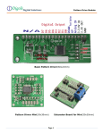
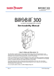
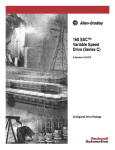
Bulletin 161
Single Phase
AC Drive
1~ / 200-240V
0.2 – 2.2 kW
Bulletin 161
Table of contents
1. Checking the scope of supply..................................................................................................... 1
2. Structure of the device................................................................................................................. 2
3. Installation .................................................................................................................................... 4
4. Wiring............................................................................................................................................ 5
4.1 Connection and description of the power terminals ......................................................................................6
4.2 Connection and description of the control terminals.....................................................................................8
5. Programming ...............................................................................................................................14
5.1 Description of the control panel ..................................................................................................................14
5.2 Entering the factory defaults (initialisation) .................................................................................................15
5.3 Putting the device into operation via the integrated control panel ..............................................................15
5.4 Clearing faults/Reset...................................................................................................................................15
5.5 Overview of the parameters........................................................................................................................16
6. Fault indications..........................................................................................................................22
7. Faults and troubleshooting ........................................................................................................25
8. Technical Data .............................................................................................................................27
9. Dimensions..................................................................................................................................28
10. Accessories ...............................................................................................................................29
Appendix A: CE Conformity ...........................................................................................................30
i
Bulletin 161
ii
Bulletin 161
Attentions and safety guidelines
Before installing the Bulletin 161 drive and putting it into operation, please read this user manual carefully and
take note of all the Attentions and safety guidelines. Always keep this product manual near the Bulletin 161
drive so that it is easily accessible.
Definition of the guidelines
ATTENTION
Failure to comply with these precautions may result in death, serious personal injury or substantial
damage to equipment.
General information
Conventions used in this manual
To help differentiate parameter names and selection tags from other text
the following conventions will be used:
•
•
parameter names will appear in italic (example: C22, d07)
selection tags for inputs and outputs will appear in [brackets] (example: [RS], [CF1])
ATTENTION
• This Bulletin 161 drive generates dangerous electrical voltages and controls potentially dangerous
rotating mechanical parts. Disregarding the guidelines provided in this manual may result in death,
serious personal injury or substantial damage to equipment.
• The installation, commissioning and maintenance of these drives may only be carried out by
experienced personnel who are thoroughly familiar with the functioning of the equipment and the
entire machine.
• The devices feature dc-bus capacitors that are live even when the mains supply is switched off. For
this reason wait at least 5 minutes after switching off the mains supply before you open the device
and start working on it. Take care that you do not touch any live parts.
• The drive is intended to be installed with a fix connection to earth. The protective earth only offers
protection for the drive, not against personal injury. According to EN 50178 it is not recommended to
use the Bulletin 161 drives on protective fault current switches as, due to a possible DC component
(rectifier load), the sensitivity of the safety switch will be reduced in the event of a failure. If
unavoidable, only type B RCD’s should be used. As a precautionary measure, the EN 50178
regulations should be observed. The stop button on the integrated control panel may not be used
for emergency purposes. The stop button can be activated via parameter b87.
ATTENTION
Earth the Bulletin 161 drive at the connections intended for this.
iii
Bulletin 161
ATTENTION
• To prevent any injuries or damage, do not touch any components located within the housing – either
with your hands or with any other objects – if mains voltage is applied or if the DC-bus capacitors
are not discharged. Do not carry out any work on the wiring or check any signals if mains voltage is
applied.
• Exercise particular caution if automatic restart is activated. To prevent injuries caused by the
automatic restarting of the drive following a power failure, install a switching component at the
mains that is deactivated in the event of a power failure and that may only be switched on again on
return of the power supply (e.g. contactor etc.). Earth the drive at the connections intended for this.
ATTENTION
• Ensure that the input voltage corresponds to the voltage indicated on the product nameplate.
Environmental influences such as high temperatures and high relative humidity are to be avoided as
well as dust, dirt and corrosive gases. The mounting location should be well ventilated and not
exposed to direct sunlight. Install the device on a non-flammable, vertical wall that does not transmit
any vibrations. Attention! Do not apply mains voltage to the output terminals U/T1, V/T2 and W/T3.
• Please contact the motor or machine manufacturers if standard motors with frequencies >50 Hz are
to be used.
• All Bulletin 161 drives are checked for dielectric strength and insulation resistance. Insulation
resistance measurements e.g. as part of a check may only be taken between the power terminals
and earth. Do not carry out any measurements at the control terminals.
• In normal operation apply the START/STOP commands via the control terminals or the control panel
and not by disconnection and reapplying input power to the drive or motor contactor. Do not install
any capacitors or suppressors to the drive output terminals.
ATTENTION
• To ensure that your Bulletin 161 drive functions safely and reliably, all the pertinent safety
regulations, e.g. accident prevention regulations, professional association regulations, EN, VDE
regulations etc. must be observed. As these regulations are implemented differently in different
countries, the user must observe the regulations that apply for his particular country. Rockwell
Automation cannot release the user from complying with the latest relevant safety regulations.
• The technical data and descriptions in this user manual have been created to the best of our
knowledge and belief. Enhancements to products are being made continually - Rockwell Automation
therefore reserves the right to make modifications without previous notice.
• In spite of the care taken in producing this manual, Rockwell Automation cannot be held liable for
any errors and damage arising from the use of this manual.
iv
Bulletin 161
1. Checking the scope of supply
Type description
161S -
A
A04
N
PK
Fifth Position
Fourth Position
Third Position
Second Position
Voltage Rating
First Position
Bulletin Number
An “S” in the
bulletin Number
denotes a single
phase input
voltage
A
200-240V 1∅
Current Rating
A01
A02
A03
A04
A05
A07
A10
Enclosure Type
N
PK
Integrated
Programmer
Keypad
IP20
1.4 A
2.6 A
3.0 A
4.0 A
5.0 A
7.1 A
10.0 A
1
Bulletin 161
2. Structure of the device
Bulletin 161S-AA01 / AA02
control panel
front cover
enclosure
RS422 serial interface (
heat sink
PE connection (M4 screw)
control terminals
screw
To wire the power terminals and
fault indication relay, loosen the
screw and open the control unit.
fault indication relay terminals
RS422 serial interface
terminal cover
power terminals
2
Bulletin 161
Bulletin 161S-161-AA03 / AA04
control unit
front cover
screw
RS422 serial interface
enclosure
heat sink
control terminals
To wire the power terminals and
fault indication relay, loosen the
screw and open the control unit.
PE connection (M4 screw)
fault indication relay terminals
RS422 serial interface
terminal cover
power terminals
3
Bulletin 161
3. Installation
ATTENTION
• Environmental influences such as high temperatures and high relative humidity are to be avoided as
well as dust, dirt and corrosive gases. The mounting location should be well ventilated and not
exposed to direct sunlight. Install the device on a non-flammable, vertical wall that does not transmit
any vibrations. Attention! Do not apply mains voltage to the output terminals U/T1, V/T2 and W/T3.
For heat convection reasons the Bulletin 161 drive must be installed vertically. Observe the specified minimum
distances to the side walls or other devices. Objects that come into contact with the inside of the drive may
result in the device being damaged.
If installed in normal environmental conditions (max. 40°C ambient) there must be a minimum of 20 mm
clearance around all sides of the drive to enable the user or installer to open the front cover to get access to the
terminals.
The figure below shows the minimum required clearances in case the Bulletin 161 is installed in an IP54
enclosure.
min. 10 cm
air circulation
Bulletin
161
min.
8 cm
min.
12 cm
min. 10 cm
When carrying out work on the Bulletin 161 drive please ensure that no objects such as cable insulation, metal
filings or dust get into the enclosure. This can be avoided by covering up the non-energized AC drive.
Temperatures may not exceed or go below the permissible temperature range from -10 to +40°C (or to +50°C
in the following cases: reduction of the reference frequency to 2 kHz; reduction of the output current to 80%
Bulletin 161 drive rated current; removal of the top cover). The higher the ambient temperature, the shorter the
life of the drive.
Do not install the device in the vicinity of devices that radiate heat.
If installing the device in a control cabinet, pay attention to the size and heat transfer capability of the control
cabinet. A fan may have to be installed.
4
Bulletin 161
4. Wiring
ATTENTION
• The installation, commissioning and maintenance of these drives may only be carried out by
experienced personnel who are thoroughly familiar with the functioning of the equipment and the
entire machine.
• The devices feature DC-bus capacitors that are energized even when the mains supply is switched
off. For this reason wait at least 5 minutes after switching off the mains supply before you open the
device and start working on it. Take care that you do not touch any live parts.
• Do not apply mains voltage to the output terminals U/T1, V/T2 and W/T3.
Layout of the power and control terminals
control unit
screw
control terminals
PE connection
control unit opened
power terminals
fault indication relay terminals
RS422 serial interface
5
Bulletin 161
4.1 Connection and description of the power terminals
The control unit must be open in order to be able to wire the power terminals. Do not apply mains voltage to the
drive connection terminals U/T1, V/T2, and W/T3 as this will result in damage to equipment. The Bulletin
161 drives feature an electronic overload protection to monitor the drive current. In the case of multi-motor
operation, thermal contacts or PTC resistors must be used for each motor. In the case of motor lead lengths >
50 m motor reactors should be used.
Connection example Bulletin 161
Mains power supply
Bulletin 161
Line filter EMC
Connection for optional
brake chopper
AC Line Input fuse ratings or other Line Side Protective Devices:
Fuse Rating
Bulletin 161S-AA01 – AA03
Bulletin 161S-AA04 – AA07
Bulletin 161S-AA10
6
:
:
: 10 A time-lag
16 A time-lag
25 A time-lag
Circuit Breaker Type and Rating
140-MN-1000 / 140M-D8N-C10
140-MN-1600 / 140M-D8N-C16
140-MN-2500 / 140M-D8N-C25
Bulletin 161
Terminal
L1, N
U/T1
V/T2
W/T3
+
_
Function
Mains connection
Motor connection
Description
1 ~ 200 - 240 V +/- 10%, 50/60 Hz +/- 5%
Star or delta connection of the motor in accordance with the rated
voltage
DC-bus connection
Connection for brake chopper
+
+1
Connection for DC-bus
reactor
If an DC-bus reactor is connected, remove the copper bridge.
Ensure that the bridge between the terminals + and +1 is installed if
there is no DC-bus reactor installed.
PE conductor connection
Power terminals
Control terminals
Fault indication relay
Earth
Terminal type
161S-AA01 / AA02: open terminals, M3.5 screw
All others: open terminals, M4 screw
Closed terminals
Closed terminals
M4 screw
MinMax Torque (Nm.)
0.8 Nm, max. 0.9 Nm
1.2 Nm, max. 1.3 Nm
0.2 Nm, max. 0.25 Nm
0.5 Nm, max. 0.6 Nm
1.2 Nm, max. 1.3 Nm
Disconnecting or connecting the motor, changing the number of poles in pole-changing motors or changing the
direction of rotation by means of an external device (e.g. contactor) is not permitted during operation.
Connecting capacitive loads is not permitted. A variety of cable types are acceptable for the drive installation.
For many installation, unshielded cable is adequate, provided it can be separated from sensitive circuits. If you
cannot separate motor cables from sensitive circuits, or if you must run motor cables from multiple drives (more
than three) in a common conduit or cable tray, shielded motor cable is recommended to reduce system noise.
(refer to Appendix A). In the case of motor lead lengths > 50 m, output reactors should be used.
Earth the drive carefully in accordance with the instructions. Avoid the use of shared protective earth
conductors if several Bulletin 161 drives are used.
)8 161S
161S
)8 )8 161S
161S
)8 )8 161S
)8 161S
The power factor cos φ of the mains power supply must not exceed 0.99. Compensation systems must be
tested for reliability to ensure that overcompensation does not occur at any time.
Attention! Input line reactors 3% impedance must be installed under the following conditions:
•
•
•
•
•
The unbalance factor is >3%.
High mains voltage dips occur.
The Bulletin 161 drives is operated on a generator.
Several Bulletin 161 drives are linked via a short common power supply bus bar.
Switched power factor correction equipment is installed.
Input line reactors may also be used to improve the power factor.
7
Bulletin 161
4.2 Connection and description of the control terminals
When using the transistor outputs 11, 12 - CM2 install a recovery diode parallel to the relay used. Otherwise
the switching relay could damage the output. Do not short-circuit the terminals H and L or P24 and L.
The control wires must be installed separately from the power lines and motor lines. They may not exceed 20
m in length. To improve noise immunity, the control wires should be screened (refer to Appendix A).
If unavoidable, transpositions between the power lines or motor lines and the control wires should be installed
at right angles.
Example of a connection
frequency reference
pot 1 - 2 kΩ
fault indication relay
230 VAC
• Wait at least 2s after turning on the power supply before issuing a start command and do not switch
off the mains supply during operation of the device.
• Each signal must be applied to the digital inputs 1 …5 for at least 12 ms.
• If input 5 is programmed as a PTC resistor (parameter C05 ), terminal L will be the corresponding
reference potential.
8
Bulletin 161
ATTENTION
• If an input is used as [FW] or [RV] and programmed as a Normally Closed (NC) contact, the drive will
start as soon as the power supply is switched on – without the input being triggered.
• Please note that a start command should not be issued if an input is used as [FW] or [RV] when the
power is switched on otherwise the motor will start immediately; wait at least 2s after switching on
the power before issuing a start command.
Terminal
Function
FM
Programmable output
Description
Analog signal (0-10 V, 1 m A)
Output frequency or
Motor current
The output frequency output is available as a pulse signal. In the
factory default the frequency is an analog signal (0-10 V),
corresponding to 0 Hz to the max. frequency.
(Match the signal under parameter b81; programming under
parameter C23).
analog signal,
frequency or current
pulse signal (frequency)
duty cycle approx. 50%
T = 4 ms (const.)
Analog signal: The relation t/T changes in proportion to the
frequency (or to the current). The maximum voltage of 10 V is
reached with the max. frequency (or 200% rated current)
(100% In ⇒ 5 V, 200 In ⇒ 10 V, accuracy approx. +/-5%
for the frequency indicator and 20% for drive current indicator.
Pulse signal: frequency = output frequency x factor of the
multiplied frequency indicator (param. b86, factory default = 1),
max. frequency 3.6 kHz.
L
0V
0 V potential for output FM
P24
24 V
24 V potential for digital inputs 1, 2, ... , 5
max. load 30 mA
Inputs 1 ... 5 are programmable. An overview of the possible
functions can be found on pages 11 and 12.
This table contains the basic setting for the terminal connections.
It is not possible to program two inputs with the same function at the
same time (see parameter C01...C05)
Inputs 1 ... 5 – with the exception of the reset and PTC input may
be programmed as either a NC contact or a NO contact (see
parameter C11...C15).
5
[RS]
4
[CF2]
3
Programmable
digital inputs
[CF1]
2
[RV]
1
[FW]
9
Bulletin 161
Terminal
Function
H
10 V reference voltage for
frequency command default
O
Analog input
Frequency command
0-10 V
Description
3RWHQWLRPHWHU
9
P$
WR N2KP
QRPLQDO 9
QRPLQDO P$
+
2
2,
/
3(
OI
L
CM2
+
2
2,
/
3(
,QSXW LPSHGDQFH
N2KP
+
2
,QSXW LPSHGDQFH
2, 2KP
/
3(
For analog input reference adjustment see parameters A11...A16.
Input OI for 4-20 mA is activated when the digital input is set to [AT]
(see parameter C01...C05).
0 V reference potential for
If no digital input is programmed as [AT] (switch frequency
frequency command inputs
command 0-10 V / 4-20 mA), the set values are added to O and OI.
Reference potential for output
Transistor output, max. 27 VDC, 50 mA
11, 12
Analog input
Frequency command
4-20 mA
The outputs can be programmed as NC contacts or NO contacts
under parameter C31 or C32 (factory default: NC contact)
11
Programmable
Digital output
Factory default: [FA1]
12
Programmable
Digital output
Factory default: [RUN]
The following functions may be programmed under the
parameters C21 and C21:
[FA1]: at frequency (Signal when the set value is reached)
[FA2]: above frequency (Signal if output frequencies >/= the
frequencies set under parameter C42 or C43).
[RUN]: Running (Signal if output frequency >0 Hz)
[OL]: Motor overload (Signal if the motor current exceeds the value
set under parameter C41).
[OD]: PID-deviation (Signal if the deviation between the set value
and the actual value returned is greater than the value set
under parameter C44 . Only available if the PID controller parameter A71- is active).
[AL]: Fault (Signal if a fault is indicated. See parameter C21, C22)
AL2
AL1
Relay output
Collective fault
250 VAC, 2.5 A resistive
0.2 A cos ∅ = 0.4
30 VDC, 3.0A resistive
0.7 A cos ∅ = 0.4
min. 100 VAC, 10 mA
5 VDC 100 mA
AL0
10
Operation: AL0-AL1 closed
Fault, power off: AL0-AL2 closed (parameter C33)
The fault indication relay is set with a time delay of approx. 2 s after
the power is switched on.
Bulletin 161
Overview of the functions of the programmable digital inputs 1 - 5
The digital inputs 1 to 5 can be programmed for 15 different functions. With exception of the PTC input
(programmable on input 5 only), every input can be programmed for any function. Parameters cannot be
programmed for two different inputs at the same time. The various functions are listed and described in the table
below. Programming is done via parameters C01...C15 (parameters C01...C05 correspond to inputs 1 to 5; programming for normally closed NC contacts or norm. open contacts NO is carried out via parameters C11...C15).
Input /
Function
[FW]
00
[RV]
01
[CF1]
02
[CF2]
03
Function
Description
Forward
Start/stop forward (see parameter A02)
Reverse
Start/stop reverse (see parameter A02)
Preset frequencies
The pre-set frequencies may be programmed in two ways:
1.) by entering the frequencies under parameter A21...A35.
2.) by selecting the corresponding digital input [CF1] ... [CF4] and
entering the required frequency under parameter F01. Press the ENTER
key to store the value entered. Press the SEL key to check that the value
entered has been stored.
[CF3]
04
Input
[CF4]
05
CF1
CF2
CF3
CF4
[2CH]
09
[FRS]
11
1
nd
2
3
ON
ON
ON
ON
4
5
6
Preset Speed
7
8
9
10
ON
ON
ON
ON
ON
ON
ON
ON
ON
ON
ON
11
ON
ON
ON
ON
ON
12
13
14
15
ON
ON
ON
ON
ON
ON
ON
ON
ON
ON
ON
ON
nd
2 Accel/Decel ramp
2 acceleration/deceleration time (parameter A92, A93)
Controller lock
The motor voltage will be switched off immediately – the motor will coast
(isolation of motor e.g. emergency).
For [FRS] two operation modes can be selected under parameter b88
1. Synchronisation of the motor speed after the waiting period
programmed under parameter b03 is over (enter 01).
2. 0 Hz start after activating [FRS] (enter 00).
synchronisation of
the motor speed
0Hz start
[FW], [RV]
input [FRS]
motor speed
waiting time
[EXT]
12
External fault
When this input is addressed, a fault indication will be issued (E12, e.g. to
be used as the input for thermal contacts)
The fault indication will be cleared with Reset.
Attention! After reset the drive will start again if a start command has
been issued ([FW] or [RV]).
[FW], [RV]
Input [EXT]
Motor will
coast
Motor speed
Input [RS] (Reset)
Fault indication relay (AL0-AL2)
11
Bulletin 161
Input /
Function
[USP]
13
Function
Restart lock
Description
The restart lock prevents a uncontrolled restart of the Bulletin 161 drive
when – after power off – the power supply returns and a start command is
issued immediately or straight afterwards. In this case the following fault
indication will be given: E13
Power supply
Start command [FW, RV]
Input [USP]
Fault indication relay
Output frequency
[SFT]
15
Parameter protection
[AT]
16
Frequency command
input OI active
(4-20 mA)
Reset
[RS]
18
A new start command or a reset will clear the fault indication.
Parameter protection protects parameters entered from being lost by
overwriting. If the software protection is activated, no data can be lost (see
parameter b31).
In the factory default input O (0-10V) is active. Switching to OI is effected
via input [AT]. If there is no digital input programmed as [AT], the
frequency command values are added to O and OI (see parameter A01).
Clearing a fault indication; reset the fault indication relay. If a reset
command is given during operation, the terminal stages are switched off
and the motor will coast.
Input [RS]
Fault indication relay
[JG]
06
Jog
Jog control is used e.g. to set up a machine manually. This is done via the
inputs [FW] or [RV] if the input [JG] is controlled. When a start command
is given, the frequency programmed under parameter A38 will be switched
directly to the motor – the start ramp is not active. For the stop command,
three different modes can be selected under parameter A39:
1.) The motor will coast
2.) The motor is slowed down at the deceleration ramp
3.) Braking of the motor using the DC brake (see parameter A54, A55)
Input [JG]
Start command [FW], [RV]
Motor speed
[PTC]
19
PTC input
Only in connection
with input 5
Reference potential
is terminal L
12
Jog control will not be possible if the jog frequency set is less than the start
frequency entered under parameter b82.
Input 5 can be programmed as a PTC input under parameter C05.
In this case, terminal L will be the reference potential (in all other cases the
reference potential will be at terminal P24).
If the PTC resistance exceeds 3 kΩ, the motor
will be switched off and the fault indicator E35
(ERROR PTC) will be issued.
5
L
Bulletin 161
PLC control
Control with internal control voltage
L100-...NFE/HFE
Bulletin
161
PLC
24 V
P24
1
2
3
4
5
L
0V
Control with external control voltage
L100-...NFE/HFE
Bulletin
161
PLC
24 V
P24
1
2
3
4
5
L
0V
13
Bulletin 161
5. Programming
ATTENTION
Wait at least 6s after programming the Bulletin 161 before issuing a start or rest command, switching
off the power supply or pressing any other key on the control panel.
5.1 Description of the control panel
The Start-key will start operation in the direction
of rotation defined under parameter F04; not
active when control is via the terminal block.
4-position LED display to display
parameters and operating data.
Stop/Reset-key. The Stop command (see b87)
or reset function for clearing fault indications can
be used via the control panel or the terminal
block.
The RUN LED will be lit when the drive
is in operation, i.e. if a start command
has been given.
The SEL key is used to select and exit input
mode.
The PRG LED will be lit when the drive
is programmed.
The ENTER key is used to save the entered
data.
The Hz and A LED will inform you
whether the output frequency or output
current is displayed.
The arrow keys are used to select parameters
and enter or modify data.
The commanded frequency can be set
via the speed potentiometer.
Programming guide
d01
d09
F01
A01
A98
b01
Entry of
parameters
F04
b89
A ..
C01
B ..
C91
C ..
14
Saving entered
parameters
Bulletin 161
ATTENTION
Before switching on the power supply the following points must be
observed:
• Check that the mains lines and motor lines are connected properly.
• The control wires must be connected at the correct terminals.
• The drive must be earthed correctly and must be installed vertically on a wall made from nonflammable material.
• All screws and terminals must be tightened.
• Check that the connected motor is designed for the frequency range in question, particularly for the
maximum frequency.
5.2 Entering the factory defaults (initialisation)
On supply, all the Bulletin 161 drives are initialized, i.e. they are programmed with the default factory
parameters. The devices may however be re-programmed to these basic settings at any time.
• Ensure that the function 01 is stored under parameter b85 (01 ⇒ on initialisation the data of the European
defaults are loaded).
• Enter function 01 under parameter b84 and save this by pressing the ENTER key.
• Press the
V , W and SEL-key at the same time.
While you are pressing the keys mentioned above, briefly press the STOP key and wait approx. 2 - 3 s
until the following is flashing: d00.
• Now release the three keys. During initialisation the following will be displayed:
EU
• The end of initialisation will be indicated by 00.
5.3 Putting the device into operation via the integrated control panel
The integrated control panel enables the Bulletin 161 drive to be controlled without the additional use of the
control terminals.
• Enter function 00 under parameter A01 (set frequency command via the integrated potentiometer) or 02
(enter the frequency under parameter F01).
• Program the function 02 under parameter A02. The drive can now be started by pressing the START key.
• The required direction of rotation can be selected under parameter F04 (00 ⇒ Forward, 01 ⇒ Reverse).
5.4 Clearing faults/Reset
There are three different ways of clearing fault indications:
• Reset input
• Switch off power supply
• Press the STOP key.
15
Bulletin 161
5.5 Overview of the parameters
Parameter Display function
number
Remarks
Display and diagnostic functions
d01
Output frequency [Hz]
d02
Motor current [A]
d03
Direction of rotation
F : Forward
r: : Reverse
0 : Stop
d04
Actual value x actual value factor [%]
(only available if the PID controller is active)
The actual value factor is set in param. A75 in the
range from 0.01 ... 99.99 The default setting is 1.0.
d05
Status of digital inputs 1 ... 5
Example: Inputs 1, 3, 4 activated
Digital inputs
5 4 3 2 1
ON
OFF
d06
Signal status of the digital outputs 11, 12
and the fault indication relays AL0-AL2
Example: Output 11 ON, no fault
Outputs
AL 12 11
ON
OFF
d07
Output frequency x frequency factor
The product of frequency factor (parameter b86)
and output frequency are displayed under this
parameter. This parameter can be used e.g. to
display the output speed of a drive or the speed of
a conveyor.
4-position values: e.g. 1500 ⇒ 1500.
5-position values: e.g. 15000 ⇒ 1500
d08
Last fault occurred
The fault indication last shown, as well as the
output frequency, motor current and DC-bus
voltage at the time of the fault may be called up
using the SEL key. The following will be displayed
if a fault has not occurred since or if the fault
indication has been deleted: _ _ _
d09
Fault indication register
The 2nd and 3rd fault indications last shown can be
called up under this parameter by pressing the SEL
key.
_ _ _ : there is no fault indication stored here
Parameter Function
number
Basic parameters
Basic
value
Setting range
F01
F02
---
0.5 - 360 Hz
st
10 s
0.1 - 3000 s
st
Input/display frequency command
1 acceleration time
Input
F03
1 deceleration time
10 s
0.1 - 3000 s
F04
Direction of rotation RUN key
00
00: Forward
01: Reverse
A--
Extended function of A group setting
Can be entered from A -- parameter.
A-group regards control setting or parameter
setting.
b--
Extended function of b group setting
Can be entered from b -- parameter.
b-group regards protection setting or others.
C--
Extended function of C group setting
Can be entered from C -- parameter.
C-group regards intelligent terminal setting.
16
Bulletin 161
Parameter Function
number
Basic parameters
Basic
value
Setting range
A01
Frequency command select
01
A02
Start command select
01
A03
Base frequency
50
00: Frequency Pot
01: Input O/OI
02: Param. F01/A20
01: Input [FW]/[RV]
02: RUN key
50 - 360 Hz
A04
Maximum frequency
50
50 - 360 Hz
Input
Analog input reference adjustment
A11
Frequency at the minimum set value
A12
Frequency at the maximum set value
0
0 - 360 Hz
A13
Analog input minimum
0
0 - 100%
A13
Analog input maximum
100
0 - 100%
A15
Start condition
01
00: Minimum speed
01: 0 Hz start
A16
Analog input filter setting
8
1 (max. filter,
slow response) to
8 (min. filter,
fast response)
0 - 360 Hz
Pre-set frequencies
A20
Frequency command if 02 has been entered 0.0
under parameter A01
0 - 360 Hz
A21
1. Preset Frequency
0
0 - 360 Hz
A22
2. Preset Frequency
0
0 - 360 Hz
A23
3. Preset Frequency
0
0 - 360 Hz
A24
4. Preset Frequency
0
0 - 360 Hz
A25
5. Preset Frequency
0
0 - 360 Hz
A26
6. Preset Frequency
0
0 - 360 Hz
A27
7. Preset Frequency
0
0 - 360 Hz
A28
8. Preset Frequency
0
0 - 360 Hz
A29
9. Preset Frequency
0
0 - 360 Hz
A30
10. Preset Frequency
0
0 - 360 Hz
A31
11. Preset Frequency
0
0 - 360 Hz
A32
12. Preset Frequency
0
0 - 360 Hz
A33
13. Preset Frequency
0
0 - 360 Hz
A34
14. Preset Frequency
0
0 - 360 Hz
A35
15. Preset Frequency
0
0 - 360 Hz
A38
Jog Frequency
1.0
0.5 – 9.9 Hz
A39
Jog Stop Mode
00
00: Coast
01: Ramp
02: DC brake
17
Bulletin 161
Parameter Function
number
V/F characteristics / boost
Basic
value
Setting range
A41
Boost select
00
00: Man. boost
01: Auto boost
A42
Manual boost
11
0 – 99
A43
Max. boost at % of base frequency
10
0 - 50%
A44
V/F select
00
00: Constant
01: Variable
A45
Maximum output voltage
100
50 - 100%
A51
DC Brake active / inactive
00
00: inactive
01: active
A52
DC Brake
Starting frequency
0.5
0.5 – 10 Hz
A53
DC Brake
Waiting time
0.0
0-5s
A54
DC Brake
Braking torque
0
0 - 100%
A55
DC Brake
Braking time
0.0
0 - 60 s
DC brake
Operating frequency range
A61
Maximum Frequency
0.0
0.5 - 360 Hz
A62
Minimum Frequency
0.0
0.5 - 360 Hz
A63
A64
A65
A66
A67
A68
18
st
Skip Frequency
0
0 - 360 Hz
st
Skip Frequency Band
1
1
0.5
0 - 10 Hz
nd
0
0 - 360 Hz
nd
0.5
0 - 10 Hz
rd
0
0 - 360 Hz
rd
0.5
0 - 10 Hz
2 Skip Frequency
2 Skip Frequency Band
3 Skip Frequency
3 Skip Frequency Band
Input
Bulletin 161
Parameter Function
number
PID controller
Basic
value
Setting range
A71
PID controller active / inactive
00
00: inactive
01: active
A72
PID Proportional Gain
1.0
0.2 – 5.0
A73
PID Integral Gain
1.0
0.0 - 150 s
A74
PID Differential Gain
0.0
0.0 - 100
A75
Process reference scale factor
1.0
0.01 – 99.99
A76
Process analog feedback
00
00: input OI
01: input O
Input
Automatic voltage regulation (AVR)
A81
AVR function select
02
00: active
01: inactive
02: not active in
deceleration
A82
Motor voltage / AVR- voltage
230
200 - 240 V
15
0.1 - 3000 s
15
0.1 - 3000 s
00
00: input set to [2CH]
01: Automatic if freq.
programmed in
param. A95 / A96
is reached
nd
0.0
0.0 - 360 Hz
nd
Second acceleration / deceleration ramp
A92
A93
nd
2 Acceleration time
nd
2 Deceleration time
nd
A94
Select 2
A95
2 acceleration ramp starting frequency
acceleration / deceleration ramp
A96
2 deceleration ramp starting frequency
0.0
0.0 - 360 Hz
A97
Acceleration Curve
00
00: linear
01: S-curve
A98
Deceleration Curve
00
00: linear
01: S-curve
19
Bulletin 161
Parameter Function
number
Automatic start after a fault
Basic
value
Settings range
b01
Restart mode select
00
00: Fault indication
01: 0 Hz start
02: Synchr.
03: Synchr. + stop
b02
Permissible power failure time
1.0
0.3 - 25 s
b03
Waiting time before restart
1.0
0.3 - 100 s
Input
Electronic motor protection
b12
Electronic overload setting
rated
current
50 - 120% of
rated current
b13
Electronic overload characteristic
01
00: increased motor
protection
01: standard
b21
Current limit operation mode
01
b22
Current limit setting
rated curr.
x 1.25
1.0
00: inactive
01: active
02: inactive in accel.
50 - 150% of
rated current
0.3 - 30 s
Current limit
b23
Current limit decel. rate
Parameter protection
b31
Selection of Software lock mode
01
00: input [SFT] active,
all functions locked
01: input [SFT] active,
Speed ref. only
02: all functions locked
03: Speed ref. only
rated curr.
x 0.58
Resolution: 1% of
inverter rated current
0 - 255
0.5 – 9.9 Hz s
0.5 - 16 kHz
00: delete fault
indic. register
01: factory default
01: Europe
0.1 – 99.9
00: STOP key always
active
01: STOP key inactive
if inp. [FW], [RV]
selected
00: 0 Hz start
01: synchronisation
01: actual freq.
02: motor current
03: dir. of rotation
04: PID act. value
05: digital input
06: digital output
07: freq. x factor
Current feedback tuning
b32
Reactive current setting
1
Initialisation / adjustment parameters
b81
b82
b83
b84
Output FM adjustment
Start frequency
PWM carrier frequency
Factory setting, basic setting (initialisation)
-0.5
5.0
00
b85
b86
b87
Factory defaults parameter
Frequency scale factor (d07)
Keypad STOP key select
01
1.0
00
b88
[FRS] select
00
b89
Display indicator under F1
Remote Keypad only
01
1
The set value links with the detection current of output current monitor, electric thermal protection and overload limit.
20
Bulletin 161
Parameter Function
number
Digital inputs 1 – 5
Basic
value
Setting range
C01
Digital input 1
00
C02
Digital input2
01
C03
Digital input 3
02
C04
Digital input 4
03
C05
Digital input 5
18
00: [FW] Forward
01: [RV] Reverse
02: [CF1] Preset. freq.
03: [CF2] Preset freq.
04: [CF3] Preset freq.
05: [CF4] Preset freq.
06: [JG] Jog
nd
09: [2CH] 2 ramp
11: [FRS] Coast stop
12: [EXT] Ext. trip
13: [USP] unintention.
start protection
15: [SFT] Softw. lock
16: [AT] 4-20 mA sel.
18: [RS] Reset
19: [PTC] PTC input
(on C05 only)
C11
Digital input 1 NO/NC
00
C12
Digital input 2 NO/NC
00
00: NO contact
C13
Digital input 3 NO/NC
00
01: NC contact
C14
Digital input 4 NO/NC
00
C15
Digital input 5 NO/NC
00
Input
Outputs 11, 12, FM, AL0-AL1
C21
Digital output 11
01
C22
Digital output 12
00
C23
Output FM
00
C31
Digital output 11 NO/NC
00
C32
Digital output 12 NO/NC
01: NC Contact
C33
Fault indication relay AL0-AL1
00
01
C41
Overload alarm setting
100
0 - 200%
C42
Frequency setting for [FA2] in acceleration
0.0
0.0 - 360 Hz
C43
Frequency setting for [FA2] in deceleration
0.0
0.0 - 360 Hz
C44
PID controller deviation
3.0
0.0 - 100%
C91
Debug mode
00
Used only by RA field
service personnel
00: [RUN] operation
01: [FA1] at frequency
02: [FA2] above freq.
03: [OL] Motor
overload alarm
04: [OD] PID deviation
05: [AL] fault
00: [A-F] analog
output frequency.
01: [A] Mot. Current
02: [D-F] digital output
frequency
00: NO Contact
00: NO Contact
01: NC Contact
21
Bulletin 161
6. Fault indications
The Bulletin 161 drives are provided with protective devices such as protection against excessive current,
excessive voltage and under-voltage. When one of the many protection functions is triggered the output voltage
will be switched off – the motor will freewheel and the device will remain in the fault indication mode until the
fault indication has been cleared.
Fault
indication
E 01
E 02
E 03
E 04
E 05
E 07
Description
Cause
Corrective action
Is the motor rated current larger
than the drive rated current?
Select drive with a higher rating.
Overcurrent
• during running
Did a sudden load increase
occur or is the motor blocked?
Avoid sudden overloads.
Possibly use drive and motor with
higher rating.
Are the motor terminals U/T1,
V/T2, W/T3 short-circuited?
Check motor lines and the motor for a
short circuit.
Is the deceleration time setting
too short?
Set a longer deceleration time.
Are the motor terminals U/T1,
V/T2, W/T3 short-circuited?
Check motor lines and the motor for a
short circuit
Is the acceleration time setting
too short?
Increase the acceleration time
Are the motor terminals shortcircuited?
Check motor lines and the motor for a
short circuit
Is the manual boost (parameter
A42) set too high?
Reduce the boost under parameter
A42
Is the motor blocked?
Check the motor load or breakaway
torque
• during deceleration
• during acceleration
• at a standstill
Is there an earth fault at the
Check the output lines or the motor for
output terminals or at the motor? an earth fault
Triggering of internal
motor protection
The internal electronic motor
protection has been triggered
due to overloading of the
connected motor.
Use a motor and converter with a
higher rating
Check the entry under parameter b12
The drive is overloaded The output current is greater
than the drive rated current
Use drive with a higher rating
DC-bus overvoltage
Set a longer deceleration time.
The motor was operated
oversynchronously
(regenerative).
Inactivate the AVR function for
deceleration (parameter A81, enter 01
or 02).
Enter a higher motor voltage under
parameter A82.
Use the brake chopper.
E 08
22
EEPROM error
Is the temperature too high or is
the drive exposed to electric
noise?
Check the environmental conditions.
Re-enter the programmed
parameters.
Bulletin 161
Fault
indication
E 09
E 11
Description
E 13
E 14
E 15
E 21
Corrective action
DC-bus undervoltage
Check the input voltage.
Brief voltage dips occur or the
mains voltage is reduced to 150160V
Processor error
Possible influence of
electromagnetic fields on the
drive?
Examine the environment of the drive
and external wiring for causes of the
fault (e.g. terminal bar).
Is the drive defective?
Have the device serviced by customer
support.
External fault
External fault indication at the
input [EXT]
Remove the cause of the fault
indication in the external wiring.
Fault cause by
triggering of start lock
Has the power supply been
switched on while the start lock
was active (input [USP])?
Activate the start lock only when the
power supply has been switched on.
Has the mains voltage been
interrupted for a short period of
time during operation and while
the start lock was activated?
(input [USP])
Check the mains.
Earth fault at the motor
terminals
Is there an earth fault between
U/T1, V/T2, W/T3 and earth?
Remove the earth fault and check the
motor.
Excess mains voltage
If the mains voltage is higher
than permitted (see "Technical
data"), the drive will be in fault
mode
Check the mains voltage.
Drive overtemperature
fault
Is the drive overloaded?
Check the motor current.
Is the ambient temperature too
high?
Check the ambient temperature.
E 22
E 12
Cause
Are the assembly clearances too Check the assembly clearances.
small? (see chapter 3 Assembly)
E 35
Control of the PTC
circuit breaker
triggering function
Is the motor overloaded?
Check the motor load.
Is the self-ventilation of the
motor – particularly at low
speeds – not sufficient?
Use an external fan if low speeds are
often used.
23
Bulletin 161
Other displays
Display
Description
A reset signal has been issued.
The Bulletin 161 drive is in standby mode.
- - -
The mains voltage has been switched off.
The waiting time before automatic restart has expired (see parameter b01 - b03).
24
EU
The factory setting has been selected and the drive is in the initialisation phase
(see parameters b84, b85). The parameters for the European market are loaded
___
No data present (e.g. display under d08, d09 if the fault indication register is empty or
display under d04 if the PID controller is not active).
Bulletin 161
7. Faults and troubleshooting
Fault
The motor
does not
start.
There is no
voltage at
terminals
U/T1, V/T2,
W/T3.
Voltage is
applied to
terminals
U/T1, V/T2,
W/T3
The
direction of
rotation of
the motor is
incorrect.
The motor
does not
accelerate.
Possible cause
Corrective action
Is there mains voltage at the input
terminals L1, N?
If so, is the LED display lit?
Check connections L1, N and U/T1,
V/T2, W/T3. Switch on the mains
voltage.
Is there a fault indication on the
display?
Analyze the cause of the fault indication.
Cancel the fault indication with the Reset
function.
Has a start command been issued
using the RUN key or via the input
[FW], [RV]?
Press the RUN key or issue the start
command at the relevant input.
Has a frequency command been
entered using the control panel?
Enter the frequency command under
F01.
If the frequency command has been
specified via a potentiometer, are the
terminals H, O and L wired correctly? If
the command has been specified
externally, are inputs O or OI properly
connected?
Check that the potentiometer is properly
connected.
Is the controller lock [FRS] active?
Is the input programmed as [FRS]?
Has a reset signal been issued?
Check the signal at input 5 (factory
default [RS]).
Has the drive been programmed under
parameter A01 and A02 in accordance
with the frequency command setting
and the start command?
Check the setting under parameter A01
and A02.
Is the motor blocked or is the load too
high?
Check the motor and the load. For test
purposes run the motor without a load.
Are the terminals U/T1, V/T2, W/T3
connected properly? Is the connection
of the terminals U/T1, V/T2, W/T3 set
up properly for the direction of rotation
of the motor?
Correct the wiring of the motor.
Have the control inputs been wired
correctly?
[FW] – Forward
[RV] – Reverse
A frequency command has not been
applied to terminal O or OI.
Check the potentiometer or external
frequency command generator and if
necessary, replace it.
Has a Preset Frequency been
selected?
Observe the priority sequence;
Preset Frequency have priority over the
inputs O and OI.
Is the motor load too high?
Reduce the motor load. If the load is too
high the overload restriction function
prevents the motor from accelerating to
the commanded frequency.
Check that the cable for the frequency
command signal is properly connected.
25
Bulletin 161
Fault
The motor
runs
unstable.
The speed
of the motor
does not
match the
frequency.
Possible cause
Corrective action
Do sudden high load changes occur?
Choose a drive and motor with a higher
rating. Reduce sudden load changes.
Resonant frequencies occur in the
motor.
Blank out the frequencies in question
with frequency jumps or change the
reference frequency.
The mains voltage is not constant.
Change PWM carrier frequency
Has the maximum frequency been set
correctly?
Check the frequency range entered.
Has the rated speed of the motor or
reduction ratio of the gear been
selected correctly?
Check the rated speed of the motor and
the reduction ratio of the gear.
The
parameters
stored do
not match
the values
entered.
The values
entered
have not
been
stored.
No entries
can be
made.
Is the control mode been set correctly
The drive
can neither under A01 and A02?
be started
nor stopped
and set
points
cannot be
specified.
Check the setting under parameter A01
and A02.
It is not
possible to
set any
values.
Is parameter protection activated?
Disable parameter protection.
Is the manual boost setting too high?
Check the boost setting and the setting
for the electronic motor protection.
The
electronic
motor
protection
(fault
indication
E05) is
triggered.
26
Enter the parameters again and save
The mains voltage has been switched
off without storing the values entered by each entry.
pressing the ENTER key.
When the mains voltage was switched
off the entered and saved values were
transferred to the power-failure safe
EEPROM. Power-off time must be at
least 6s.
Is the electronic motor protection
setting correct?
Enter the parameters again and save
each entry. After setting the parameters,
switch the power off for at least 6s.
Bulletin 161
8. Technical Data
Series
Type
Bulletin 161SAA01
AA02
AA03
AA04
AA05
AA07
AA10
Drive rating (kW)
0.2
0.4
0.55
0.75
1.1
1.5
2.2
Input rated current (A)
3.1
5.8
6.7
9.0
11.2
16.0
22.5
Output rated current (A)
1.4
2.6
3.0
4.0
5.0
7.1
10.0
Mass (kg)
0.85
0.85
1.3
1.3
2.2
2.2
2.8
Mains voltage (V)
1 ~ 200 V -10% to 240 V + 5%, 50/60 Hz +/- 5%
Output voltage
3 ~ 0 - 200 ... 240 V in accordance with the mains voltage
Type of protection
IP20
PWM carrier frequency
0.5 - 16 kHz
V/F characteristics
V/F characteristics for constant torque and variable torque; variable output voltage,
Base Frequency and Maximum Frequency.
Type of control
Voltage-driven, PWM sinus coded, IGBT-Power module
Output frequency
0.5 - 360 Hz
Accuracy of frequency
command
Digital: +/- 0.01% of max. frequency
Analog: +/- 0.2% of max. frequency
Frequency resolution
Digital: 0.1%, analog: max. frequency/1000
Overload capacity
150% for 60 s (once in a period of 10 min.), max. 220%
Starting torque
min. 150% at frequencies >3 Hz
Braking torque by
feeding back into the
capacitors
Bulletin 161S-AA01 ... AA04:
Bulletin 161S-AA05 ... AA07:
Bulletin 161S-AA10:
DC brake
Analog inputs
Starting frequency, braking torque, running time are variable.
Digital inputs
100%
70%
20%
0 -10 V, input impedance 10 kΩ
4 - 20 mA, input impedance 250 Ω
PTC input
5 free programmable inputs, 24 V PNP logic, NO contacts or NC contacts
Analog outputs
1 analog output to either display the output frequency or the motor current.
For output frequency can be switched as an impulse output.
Digital outputs
2 open collector outputs for (for either operation indication, at frequency / above
frequency, overload alarm, PID controller deviation exceeded).
1 fault indication relay (change-over contact)
Protection functions
Overcurrent, overvoltage, under-voltage, electronic motor protection,
overtemperature, earth fault, overload etc.
Other functions
15 preset speeds, PID controller, parameter protection, restart lock,
RS422 serial interface, skip frequencies etc.
Ambient temperature
-10 - +40 °C (up to +50 °C in the case of reduction of reference frequency
to < 2 kHz, restriction of output current to 80% and removal of top cover)
Relative humidity
20 - 90% relative humidity, no condensation
Vibration/shock
5.9 m/s2 (0.6 G) 10 - 55 Hz
Max. installation altitude 1000 m above sea level
Options
Line filter modules
Standards
EN 61800-3 EMC guidelines in connection with optional line filter modules
in line with installation guidelines,
EN 50178 Low-Voltage guideline,
UL
27
Bulletin 161
9. Dimensions
Bulletin 161S-AA01 / AA02
Bulletin 161S-AA03 / AA04
98
67
Hz
PRG
A
Hz
RUN
MAX
SEL
118
MIN
120
110
PRG
A
MIN
130
RUN
MAX
SEL
10
5
10
5
5
Ground Terminal
Ground Terminal
4
7
80
110
7
4
Main Circuit Terminal
Main Circuit Terminal
Alarm Terminal
129
Control Circuit Terminal
Bulletin 161S-AA05 / AA07
Bulletin 161S-AA10
140
128
MIN
MAX
RUN
Air
Hz
180
A
168
Hz
PRG
180
168
140
128
RUN
Control Circuit Terminal
2.5
2.5
H=107
Alarm Terminal
A
PRG
MI N
MAX
SEL
SEL
5
5
7
5
7
10
5
Air
Ground Terminal
Main Circuit Terminal
Main Circuit Terminal
Alarm Terminal
153
164
Alarm Terminal
Ground
Terminal
Control Circuit Terminal
6
3.5
Control Circuit Terminal
28
Bulletin 161
10. Accessories
Line Filter Module
Specifications
Nominal
Voltage
Line Filter
Module
[V]
161S-RFA-6-A
161S-RFA-9-B
161S-RFA-22-C
240 +5%
240 +5%
240 +5%
Current:
Nominal
Current
at 40°C
[A]
Leakage
Current
at 50 Hz
(mA)
Test voltage
[VDC for 2s]
ph. / ph;
ph. / ground
2x 6A
2 x 10 A
2 x 23 A
< 3,5
< 3,5
< 10
1400 / 2800
1400 / 2800
1400 / 1400
at 40°C ambient temperature
Input wire Output cable
max. cross cross section
section
[mm2]
[mm2]
(L) 4/4 (N)
4/4
4/4
3x1.5
3x1.5
3x2.5
Heat
dissipation
[W]
5
6
9
Dependence of current on ambient temperature
IB 1,2
IN
1,0
Overload:
150% IN for 10 min
Frequency:
50 / 60 Hz
Material:
steel, surface refined
Humidity class:
C
0,4
Operation height:
< 1000 m without derating
> 1000 m, IN-2%, for each 1000m
0,2
0
Temperature range:
-25°C to +85°C
Connections
Input terminals IP 20 and PE-screw M5
Load side: cable, unshielded
0,8
0,6
0
20
T
40
60
80
i °C
temperature in °C
100
Filter Dimensions (mm):
F
type 1
D A
C
Line Filter Module
161S-RFA-6-A
161S-RFA-9-B
161S-RFA-22-C
E
B
A
120
130
180
B
80
110
140
C
25
27
29
D
110
118
168
E
67
98
128
F
2x6
4x6
4x6
29
Bulletin 161
Appendix A: CE Conformity
The Bulletin 161 is CE marked for conformity to the Low Voltage (LV) Directive 73/23/EEC when installed as
described. It also has been tested to meet the Council Directive 89/336/EEC Electromagnetic Compatibility
(EMC).
The standards used are:
LV
EMC
Important:
EN50178, EN60204-1, EN60950
Emissions:
Immunity:
EN61800-3 (EN55011, Group 1, Class B)
EN61800-3 (Industrial Environment).
The conformity of the drive and filter to any standard does not guarantee that the entire
installation or machine will conform. Many other factors can influence the total installation and
only direct measurements can verify total conformity. It is therefore the responsibility of the
machine manufacturer or end user to ensure that conformity is met.
General Notes and Instructions:
)
The motor cable should be kept as short as possible in order to avoid electromagnetic
emission as well as capacitive currents. The cable length increases the capacitive current
and electromagnetic emission.
It is recommended that the motor cable length does not exceed 50 m.
)
)
)
)
It is always recommended to install output reactors if the cable length exceeds 50 m.
The filters contain capacitors between the phases and the phases to ground as well as
suitable discharging resistors. But after switching off the line voltage wait a minimum of
60 seconds before removing protective covers or touching terminals to avoid an electric
shock.
The use of ground fault monitoring devices (RCD’s) is not recommended. If unavoidable
only monitoring devices which are suited for DC-, AC- and HF-ground currents (type B
RCD’s) should be used. It is recommended to use devices which responsiveness and time
characteristics are adjustable, to avoid nuisance tripping during power up the drive.
The thermal capacity of the line filter is guaranteed up to a maximum motor cable length of
50 m.
The line filters have been developed for use in grounded systems. Use in ungrounded
systems is not recommended.
Essential requirements for a conforming EMC installation
1. An input line filter module (see table below) must be installed to reduce conducted emissions.
Line Filter Selection Guide
Bulletin 161
161S-AA01NPK
161S-AA02NPK
161S-AA03NPK
161S-AA04NPK
161S-AA05NPK
161S-AA07NPK
161S-AA10NPK
30
Input Voltage
1 ~ 220 V -10% - 240 V +5%
1 ~ 220 V -10% - 240 V +5%
1 ~ 220 V -10% - 240 V +5%
1 ~ 220 V -10% - 240 V +5%
1 ~ 220 V -10% - 240 V +5%
1 ~ 220 V -10% - 240 V +5%
1 ~ 220 V -10% - 240 V +5%
Line Filter Module
161S-RFA-6-A
161S-RFA-6-A
161S-RFA-9-B
161S-RFA-9-B
161S-RFA-22-C
161S-RFA-22-C
161S-RFA-22-C
Bulletin 161
Compliance of the Bulletin 161 drive to the conducted emissions levels with appropriate line filter module is as
follows:
PWM Carrier Frequency
<16 kHz
<5 kHz
<16 kHz
Motor cable length
10 m
20 m
50 m
Limit
Class B
Class B
Class A
2. All motor cables must be shielded cable, or be in grounded metal conduit.
3. All control and signal wiring must use shielded cable or be in grounded metal conduit.
4. Grounding of equipment and cable shields must be solid, with low impedance connections.
5. Ensure that the protective conductor terminal (PE) of the filter is properly connected with the protective
conductor terminal of the drive. The filter must be solidly and permanently connected with the ground
potential to avoid electric shock.
POWER
HITACHI
RUN
Hz
A
PRG
RUN
FUNC.
STOP
RESET
1
MI
2
MAX
STR
L 100
WARNING
HAZARD OF PERSONAL INJURY OR
ELECTRIC SHOCK
Disconnect incoming power and wait
5 minutes before opening front case.
PE-connection
PE, L1, N
31
Bulletin 161
General instructions for an EMC compliance installation
Enclosure
•
Typical IEC metal enclosures are adequate.
•
The ground connection of the enclosure must be solidly connected to the PE terminal of the drive. Good
conductivity must be assured – grounding must provide a low impedance path for high frequency signals.
•
All wiring, except input power leads, must be shielded cable.
•
Input power, output power and control wiring inside the enclosure must be physically separated.
•
Input power, output power and control wiring outside the enclosure must use separate shielded cables
or separate metal conduit.
Cable Clamps
•
Use suitable EMC cable clamps.
•
The connection area must be 360 degrees around the shielded cables.
•
When using conduit, the contact point of metal must be free of paint or non-conductive surfaces
and solidly connected with good conductivity to the enclosure.
Motor Cable
•
The cable between the drive and motor must be 4-wire shielded cable (three phases and ground).
•
Do not exceed the maximum motor cable length for the specific line filter module used.
•
Inside the enclosure, shielded motor cable should be used as close to the drive’s output terminals
as possible.
•
Where the shielded motor cable exits the enclosure, an EMC cable clamp, or metal conduit must be used
to solidly connect the cable shield to the enclosure.
•
The shield on the motor side must be solidly connected to the motor housing with an EMC cable clamp,
or conduit, providing good conductivity from the cable shield to the motor housing.
Control Wiring
•
Control wiring must use shielded cable or grounded metal conduit.
•
The shield must be connected to PE at both ends of the cable.
•
Inside the enclosure, shielded control wiring should be connected as close to the drive’s control terminals
as possible.
32
Publication 161-5.0EN – May 1999
Copyright 1998 Rockwell International Corporation. All rights reserved NB 571X