1
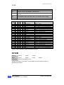
DMC2 CONNECTIONS
X22
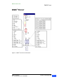
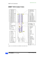
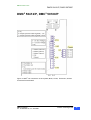
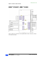
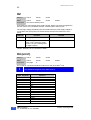
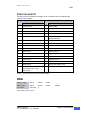
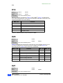
Figure 4. shows the connector X21. Table 15 describes the function The motor
2
connections are the same for AC and DC supplied DMC s.
Use the appropriate threaded strain relief with shield connection listed in User’s
Manual part A to secure the motor cable to the motor.
The cable shield must make secure metallic contact with the strain relief.
2
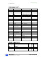
DMC X21
Function
1
Shield
2
PE
3
PE
4
Motor U
5
Motor U
6
Motor V
7
Motor V
8
Motor W
9
Motor W
2
Table 15. Motor Connection (X21) to DMC .
X22
2
51540
2
51540
DMC P
DMC
Connector
53080
See User’s Manual part A.
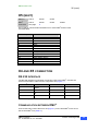
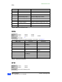
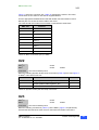
Make the following dynamic brake circuit connections (Table 16) from X22 Figure 4
2
on DMC unit to X34 on PS unit.
2
DMC X22
Function
PS unit X34
1
Output dynamic brake regulator, driver
1
2
Output dynamic brake regulator, -DC
2
3
Reserved
3
Table 16. Dynamic brake (X22 and X34) Connection.
X23
2
51540
2
51540
DMC P
DMC
Connector
53080
See User’s Manual part A.
2,
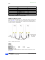
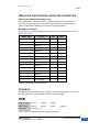
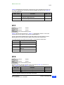
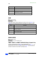
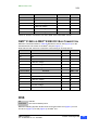
Make the following connections (Table 17) at the DMC (Figure 4 for placement)
X23 and the terminal block at the motor for thermistor and brake connections.
DMC2 Connection
Doc. No.9032 0027 11, Rev. 21.03.2001
Inmotion Technologies AB
21