1
Section 3 - ANSI / OSHA Requirements
This FallTech Personal Fall Protection System component fully complies
with ANSI Standards A10.14 - 1991 and ANSI Z359.1 - 1992, and all
current OSHA requirements for fall arrest and fall restraint in general
construction, including 1910.66 Appendix C and 1926.500.
Section 4 - Employer & User Training Responsibilities
OSHA requires that an EMPLOYER shall provide a training program
for each employee who might be exposed to fall hazards. The program
shall teach each employee to recognize the hazards of falling, and
train each employee in
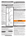
FIG. 2B CLC GRIPLOCK™
the procedures to be folFALL PROTECTION SYSTEM (Typical Setup)
lowed to minimize fall
hazards. Prior to work
requiring a Personal Fall
Arrest System (PFAS)
(FIG. 2A) or Fall
Anchor Point
Restraint/Positioning
System (FIG. 2B), the
USER shall be trained by
Rope Grab
a competent person to
(Decelerator)
properly inspect, use,
store and maintain this
equipment according to
the requirements of ANSI
Z359.1 - 1992, and the Lifeline:
25 Feet
Manufacturer’s
(7.6 m)
Instructions.
or 50 Feet
(15 m)
As part of the training
process, the user of
Lanyard with
these Anchor Devices
Shock Absorber
must:
1) Become familiar with
ALL instructions printed in
this manual;
2) Be trained in the correct use and care of this
Full Body
component;
Harness
3) Be aware of its application limits; and
4) Know and understand
the consequences of
improper use of this
component.
NOTE: You must be
trained in the use of
these Anchor Devices
without being subjected
Line Tensioner Or
to a fall hazard. For best
Counterweight (Min.
results, Personal Fall
5 Pounds/2.3 kg)
Protection System training should be reviewed
or repeated at least one
per year.
(FIG. 2A), only a Manual Rope Grab (which can be locked into a
fixed, non-sliding position on the properly anchored Lifeline) may be
used. 4) Minimizing of swing falls. Anchorage point must be directly
above user (FIG. 3A).
5) Fall path clearance check. The amount of clearance needed is
based on the type and length of the connecting subsystem used, and
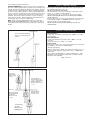
the location of the anchorage. (FIG. 3B) Total fall distance is the maximum free fall distance (6 feet/1.8 m) plus the distance the Lanyard
shock absorber elongates (max. 3.5 feet/1.1 m). Total fall distance
may not exceed 9.5 feet (2.9 m).
6) Avoidance of sharp edges and other hazards. You must protect
workers by padding or sheathing unprotected sharp edges while work
is being done. All workplace hazards must be eliminated, controlled,
or considered before any work takes place.
7) Rescue and evacuation plan. You must provide a means of rescue
and evacuation for workers should a fall occur.
8) Immediately dispose of equipment which has been subjected to
fall arrest forces.
Section 6 - Visual Inspection Before Each Use
To make sure that this FallTech Anchor Device will perform properly as
part of a Personal Fall Arrest or Fall Restraint System, it is important
that you visually inspect it BEFORE EACH USE. (This Anchor Device
should also be inspected by a competent person other than yourself at
least twice a year.)
What to look for when visually inspecting Anchor Devices:
1) Look to see that Anchor Device is not cracked, bent or deformed.
2) Make sure that Anchor Device is free of excess dirt, paint, oil or
other contaminants which could affect its operation.
3) If Anchor Device has been subjected to fall arrest (or equivalent)
forces, remove it from service immediately and destroy.
4) Look to see that all Anchor Device labels and warnings are securely fastened and still legible. Missing or illegible labels and warnings
must be replaced by contacting FallTech.
5) Look to see that other FallTech Personal Fall Protection System
components (Full Body Harnesses, Lanyards, Rope Grabs, Lifelines,
etc.) are ready for use by visually inpecting each one according to the
User’s Instructions provided by the manufacturer with each component
part.
6) Record the results of your Anchor Device inspection in the Log provided in Section 11 of this manual.
WARNING
If this Anchor Device is damaged, or has been subjected to fall
arrest (or equivalent) forces, it must be removed from service
immediately and destroyed.
NOTE: Harsh environments and weather, prolonged use and other
extreme working conditions may require you to have this Anchor
Device fully inspected by a competent person other than yourself at
least twice a year.
Section 7 - How To Install Anchor Devices
Section 5 - The Fall Protection Plan
As an employer, you must be aware of the factors which affect the
safety of your workers before, during and after a fall. Having a Fall
Protection Plan ready before work begins is the best way to ensure the
ultimate safety and well-being of your employees.
Your Fall Protection Plan Must Include:
1) Proper anchorage. A PROPERLY SELECTED ANCHORAGE POINT IS
CRITICAL TO THE SUCCESS OF A PERSONAL FALL ARREST SYSTEM
(PFAS). OSHA 1910.66 APPENDIX C REQUIRES THAT AN ANCHORAGE POINT (structural beam or member) MUST SUPPORT A STATIC
LOAD OF 5,000 POUNDS (22.2 kN) — PER PERSON ATTACHED TO
THE ANCHORAGE POINT. The anchorage point must be selected to
reduce fall hazards, and to avoid worker contact with objects in the
fall path (FIG. 3B).
2) Limit free fall to 6 ft. (1.8 m) or less. Users of Personal Fall
Protection Systems must not work above the anchorage point. (FIG.
3B) The connecting subsystem of one worker (Lifeline, Lanyard, etc.)
must not cross or tangle with that of another worker. Connecting
subsystems must never be knotted or tied to each other.
3) Positioning / Fall Restraint Only Plan. When a Rope Grab is
attached to a Lifeline for work positioning/ fall restraint purposes
WIRE FORM ANCHOR: FallTech Wire Form Anchors (FIG. 1A) are
designed for attachment to a support member capable of sustaining
the minimum static load required for a Personal Fall Arrest or Fall
Restraint System — 5,000 pounds (22.2 kN), per attached worker.
Grasp the lower portion of the Anchor (below the large loop) and
squeeze the two sides tightly together to open up the large top loop.
Slip the opened top loop past the support member (pipe or beam),
turn 90° and release. Connect a design-compatible Lifeline snap hook
or self-locking Carabiner to the smaller formed “eye” on the bottom of
the Wire Form Anchor.
FALLTECH GRIP ANCHOR: FallTech Grip Anchors (FIG. 1B) are
designed for attachment to a support beam capable of sustaining the
minimum static load required for a Personal Fall Arrest or Fall Restraint
System – 5,000 pounds (22.2 kN), per attached worker.
BEFORE INSTALLING THE ANCHOR, A 3/4” HOLE MUST BE DRILLED
THROUGH THE SUPPORT BEAM.
Must be used in vertical applications only. Grasp the Anchor with your
thumb in the eye and your fingers on the flanges. Pull together and
insert Grip through pre-drilled 3/4” hole in support beam. Release
thumb and fingers. The Grip MUST FIT SNUGLY. A too-loose fit may
cause the Grip to work itself free causing serious injury or death. Attach
a design-compatible Lifeline snap hook or self-locking Carabiner