1
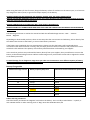
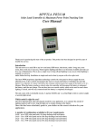
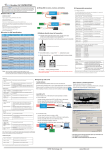
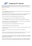
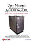
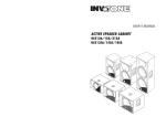
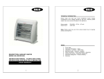
Off Grid Solar Charged Inverter PR293
Renewable energy series - Light and power from the sun By: Net Comm Solar
User Manual
Components
Front
USB Port 12V Output
LED Status
On/Off Switch
Rear
3 Pin Socket 230V
Output
230V Input
Inverter control Switch
PV Input Socket
12V Input Battery
cables
Introduction
Thank you for purchasing this Off Grid Charge Inverter. It uses the latest technology using a microprocessor
controller to charge and monitor the battery and load. It uses a number of proprietary algorithms, to get the fastest
maximum efficiency from the panel (MPPT) to charge the battery without overloading the battery, and to do battery
monitoring and display the battery status.
A real time LED display indicates the battery status and other functions.
The Model number, serial number (if applicable), battery charge current and PV size are located on the rear of the
unit. Under no circumstances must you use the charge current or PV panel other than what is on the label, as
damage to the unit and or battery may arise, and will void any warranty.
Before using the equipment, ensure that you connect the battery first, then the mains, then the solar panel.
In accordance with our policy of continual improvement, Microsolve C.C. reserve the right to alter specifications,
materials and dimensions without prior notice. E&OE.
Unpacking
When you purchase the unit, the battery and solar panel are not provided in the same box, and must be purchased
separately. In some cases, the supplier may have sold a bundle which may include the battery and solar panel.
The following is a list of the components that come together in the Off Grid Charge Inverter. Off Grid Charge
Inverter control unit
10 amp Mains cable with a 16A 3 Pin plug and an IEC socket
5 meter - 2 core cable, with a 2 pin screw socket on one side and with a PV plug and socket to connect to the PV
panel on the other side
Check for damage to the control unit during shipping. If the unit is damaged in any way, we recommend that you
return it to the supplier to verify proper operation.
Sine Wave Output
Depending on the model you have purchased, it can either be a modified Sine Wave or a Pure Sine Wave.
The unit converts the 12V DC from the battery to 230V AC using power electronics. The AC can used to power up a
number of mains equipment. It is important that you do not overload the inverter. In the case that the inverter is
overloaded, it will shut down, and will require you to switch the unit off, remove the loads, and switch on again.
Reconnect the loads one a time to see which load is over loading the inverter. If the inverter you have is too small
for your application, then you may have to purchase an inverter which can handle more load. Speak to your
supplier to see what other solutions that they may have for your application.
The inverter output is controlled by the On/Off switch next to the 3 pin socket at the rear of the unit. When the
mains is available, there is power at the 3 pin socket, irrespective if the switch is in the On or Off position. When the
mains fails, and the switch is in the ‘Off’ position, the inverter is disconnected and there is no power to the load.
When the mains returns, the internal switch will immediately pass the mains to the socket.
In the case that the switch is in the ‘On’ position, while mains is available, there will be power at the socket. When
there is a mains failure, the internal relay switches over, and the inverter starts, and approximately 2 seconds later,
there will be power at the socket and the load is powered by the inverter. When the mains returns, the internal
relay immediately transfers the mains to the socket, and switches the inverter off.
This ensures that the inverter only works when the user wishes to have battery backup, and preserves the battery
should there be a mains failure during a time the user is not making use of the battery backup, thereby preserving
the battery for when it is required by the user.
When the switch is in the off position, the inverter does not run, placing the unit in a low power drain mode
preserving the energy in the battery for when you need it. In this mode the battery is always maintained at full
power via the solar panel or mains input.
Modified Sine Wave – Suitable for most loads such as TVs, P.C.s, decoders, LED and CFL lamps, cell phone chargers.
Pure Sine Wave – Suitable for devices with electric motors, fans, micro waves, gate controllers, audio equipment,
TVs, P.C.s, decoders, LED and CFL lamps, cell phone chargers.
Operation
The unit has 4 major components, namely a solar panel, mains input, lead acid battery, and the
electronics which controls the inverter, charging and discharging process to ensure maximum efficiency
both from the panel and battery lifespan.
Solar Panel (PV)
The Solar panel is one of the sources used to charge the battery. Before connecting the PV panel, ensure
that the ‘On/Off’ switch in the front of the unit is in the ‘Off’ position. Locate the PV cable, and locate the
2 pin screw plug. The plug has a locating pin. Ensure that the 2 pin plug slides into the PV input plug at
the rear of the controller. Screw the lock nut in for a good connection. Connect the battery – see
‘Connecting Battery’ section.
Now switch the front panel ‘On/Off’ switch to the ‘On’ position in order to charge the battery, and then
verify that the ‘PV’ light is on, indicating that the PV is applying energy to the unit. In the case the battery
is over discharged, the Buzzer will emit a sound every few seconds, until the battery voltage reaches a
minimum point of charge, then the sound will stop. If there is no ‘Mains’ input, then in this case remove
all the 12V loads, switch off the inverter by switching off the ‘3 Pin Socket’ switch, so that the PV panel
can supply as much energy to the battery as possible, in order that the battery can recover the energy
from the PV panel. Running any loads at this time will simply not allow the battery to charge fully, and if
this is the only source of energy available to charge the battery, will mean that the battery will never
become fully charged, thereby affecting the ‘Run Time’ of the inverter.
For best results, the PV panel must be placed in direct sunlight, and at no time must there be any
shadows cast on the PV panel. These shadows reduce the amount of energy the PV panel produces.
Always ensure that the PV panel is perpendicular to the sun light, as this is the time that the PV panel will
produce the maximum amount of energy captured from the sun. There is a difference in the amount of
energy that the PV panel can harness during summer and winter days. The panel collects more energy on
summer days than it does on winter days. The amount of time that the sun is shining on the PV panel also
varies from summer to winter. In the case that the panel is left alone to charge the battery, or in the case
that the PV panel is mounted permanently, then a compromise in the PV position must be made. A
typical site is shown in the following diagrams. By doing a visual inspection at midday in summer and
winter, selecting the average position between summer and winter solstice will be a good position to
place the panels for an all year round position. It must be noted, that there is between 5 and 6 hours of
useable sunlight on a daily basis, and if there are clouds in the sky, then the amount of available sunlight
will be reduced. This in turn will provide less energy to the battery charging process.
When selecting a permanent position for the PV panel, ensure that the panel will be in the path of the sun,
both in winter and summer, and that there is little or no possibility of shadows being cast onto the PV
panel from obstructions. Also ensure that there is easy access to the PV panel, as it will require periodic
cleaning of the glass due to dust or bird droppings. If the area in which the PV panels are installed, is very
dry and dusty, then the possibility of dust covering the panel increases, and periodic cleaning of the surface
will ensure a good transfer of energy to the battery charger. In the case bird droppings are noted on the PV
panel, it must be cleaned, or the performance of the panel will be affected. Using water and a cloth
should suffice to clear the dust or bird droppings.
The PV panel comes prewired with a 3 meter wire and 2.5mm plug. Insert this plug into the Solar Charged
Supply socket market PV Input.
Mains Input
The Mains Input is another one of the sources used to charge the battery, but it also supplies power to the
load, irrespective of the state of charge of the battery. Use the mains wire extension provided to connect
the ‘Mains’ to the unit on the IEC connector on the rear of the controller.
Ensure that the On/Off switch is in the ‘On’ position in order to charge the battery, and then verify that the
‘PV’ light is on, indicating that the PV is applying energy to the unit. In the case the battery is over
discharged, the Buzzer will emit a sound every few seconds, until the battery voltage reaches a minimum
point of charge, then the sound will stop. If there is no ‘Mains’ input, then in this case remove all the 12V
loads, switch off the inverter, so that the PV panel can supply as much energy to the battery as possible, in
order that the battery can recover the energy from the PV panel.
Connecting the Battery
The battery is the energy source which the inverter uses to drive your load. Any problems with your battery will have
a direct influence on the capability of the inverter to supply your load.
When using the battery for the first time, charge the battery at least for 24 hours on the mains input, or at least one
day charge from the PV panel, to get the full output capacity of the battery.
BEFORE CONNECTING OR REMOVING THE BATTERY, ENSURE THAT THE FRONT PANEL ON/OFF
SWITCH IS IN THE OFF POSITION. Failure to do this, may cause damage to the Off Grid Charge Inverter or to your
load. This action will also void all warranties.
REVERSE CONNECTION OF THE BATTERY WILL ALSO VOID ALL WARRANTIES.
BEFORE MAKING ANY CONNECTIONS MAKE SURE THAT YOU ARE CONNECTING THE CORRECT COLOUR WIRE TO
THE BATTERY.
The following convention is used in this manual and with the Off Grid Charge Inverter :- RED – Positive
BLACK - Negative
Depending on which model you have, there are two ways that the unit connects to the battery, either directly from
the cables from the unit to the battery, or via an inline battery connector.
If the battery was supplied by the unit representative, chances are that the battery will have already been
connected to the inline connector correctly, and you simply have to mate the connectors and push them in until a
solid click is felt and heard. The polarity of the battery would have been confirmed by your supplier.
In the case that you have not purchased the battery directly from your supplier, then you will have to connect the
battery to the Off Grid Charge Inverter. Before commencing ensure you have the correct tools to tighten the cables
to the battery terminals.
To avoid damage, fire or dangerous usage must you under no circumstances use a different capacity of battery
for what the unit maximum current has been set for.
Battery Charge table
Maximum Charge Current
Battery Capacity Amp Hour
Minimum Recommended solar panel size
20Amp
1.5A
35W
75W
3A
4A
30Amp
45Amp
6A
65Amp
150W
80Amp
7.5A
180W
100Amp
10A
12.5A
125Amp
250W
150Amp
15A
350W
100W
300W
Cables with ring connectors
Check the battery and locate the ‘Negative’ terminal on the battery. This is usually marked with a ‘-‘ symbol, or
with a BLACK washer or other marking such as “Neg’. Now take the BLACK wire, and
locate the end ring, and attach it to the battery terminal. Tighten the screw or bolt well. Tug on the cable and
ensure that the ring does not move. If it does move, then retighten the screw/bolt. DO NOT OVETIGHTEN, or you
may strip the thread either in the battery or strip the bolt.
Next locate the ‘Positive’ terminal on the battery. This is usually marked with a ‘+‘ symbol, or with a RED washer or
other marking such as ‘Pos’. Now take the RED wire, and locate the end ring, and attach it to the battery terminal.
Tighten the screw or bolt well. Tug on the cable and ensure that the ring does not move. If it does move, then
retighten the screw/bolt. DO NOT OVETIGHTEN, or you may strip the thread either in the battery or strip the bolt.
In Line Battery Connector
In the case the inline connector has not been connected to a battery, then follow these instructions. Check the
battery and locate the ‘Negative’ terminal on the battery. This is usually marked with a ‘-‘ symbol, or with a BLACK
washer or other marking such as ‘Neg’. Now take the BLACK wire, andlocate the end ring, and attach it to the
battery terminal. Tighten the screw or bolt well. Tug on the cable and ensure that the ring does not move. If it does
move, then retighten the screw/bolt. DO NOT OVETIGHTEN, or you may strip the thread either in the battery or
strip the bolt.
Next locate the ‘Positive’ terminal on the battery. This is usually marked with a ‘+‘ symbol, or with a RED washer or
other marking such as ‘Pos’. Now take the RED wire, and locate the end ring, andattach it to the battery terminal.
Tighten the screw or bolt well. Tug on the cable and ensure that the ring does not move. If it does move, then
retighten the screw/bolt. DO NOT OVETIGHTEN, or you may strip the thread either in the battery or strip the bolt.
Connect to the unit inline connector by mating with the battery side connector, and push in until you feel and hear
a click. To disconnect the in line connector, simply pull hard on each connector, and they will separate.
The advantage of the inline connector, is that you can change batteries very quickly with out tools or without
having to worry about the polarity being correct. ALWAYS remember to switch the unit off when disconnecting or
connecting the battery.
Electronics Charger and Controller
The heart of the system is a 24Bit microcontroller. It monitors all the inputs and controls the outputs. The inputs
will be the voltage of the PV panel, battery voltage, mains charger voltage, the battery current reference, mains
input signal, battery charge current value.
Outputs will be battery charge PWM, mains load control, inverter enable, mains battery charge relay and the status
of the battery LEDs and buzzer.
LEDs
Battery Status
An audible alarm indicates when the battery is reaching a critical low voltage, and when the load is disconnected.
Another LED indicates when the inverter is active, when there is mains available, and when the unit is using the
mains to charge the battery.
PV Input
There is also LED indication when there is energy on the PV
USB Port
There is a USB port, which can be used to charge cell phones or used for any other 5V electronic equipment.
Dual 12V Output
There are 2 ports available with 12V, protected via a thermal fuse, which can be used for 12V LED lighting during
the power failure, or any other 12V power equipment that may be required.
In the case there was an overload, switch off the power to the Off Grid Charge Inverter. Remove all the loads
connected to the USB port and dual 12V ports. Switch the Off Grid Charge Inverter back on again. The fault should
be cleared. If the overload continues to trip, there may be 2 reasons. Either the load being connected draws in the
excess of 5Amps, or the load has a fault.
Specifications:
USB output
5V at 1Amp
Combined 12V DC output
5Amps
10Amps internal Fuse protected, remove load to reset fuse
PV size
from 20Watts to 250Watts model dependent
PV input Voltage
from 25V to 35V model dependent PV fully loaded MPPT 1718V or 27/30V – model dependent
PV current
from 1.4Amps to 8Amps model dependent
Inverter power
500Watt or 1000Watt - model dependent Inverter output
voltage
200V to 250V dependent on battery voltage
Inverter wave output
Modified sine or pure sine wave - model dependent Inverter
load
100% overload for 1 second
Unit physical size
W = 235mm, D = 350mm, H = 210mm
Weight
500W model – 6Kg, 1000W model 7Kg
Packed size
420mm X 255mm X 230mm
Packed weight
500W model – 7.5Kg, 1000W model – 8.5Kg
Battery and Solar Panel sold separately. When ordering, battery size and solar panel must be advised so
that the unit is set up at the factory for your requirements.
E mail: [email protected] www.netcommsolar.com