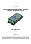
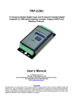
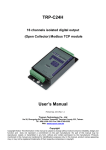
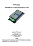
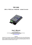
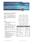
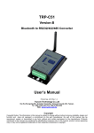
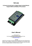
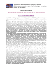
1
TRP-C28 User’s Manual
Introductions
TRP-C28 provides 4 optical isolated digital input channels that allow you to input the logic signal from 0
to 30V DC and 4 power relays output . All channel features screw terminals for the convenience
connection of field signals as well as LED to indicate channel status. Each output power relay equips with
high surge current suppressors varistor to entirely protect your module and devices without damage when
irregularly high power voltage input. TRP-C28 can be configured and conduct self-test by outside dipswitch without complicated setting and connection. Build-in a full set of command, watch-dog, auto reset
function the module can be bi-directionally remote controlled by RS485 protocol.
Features
¾All communication's command are perform in ASCII.
¾Programmable in virtually any high-level language.
¾4-CH isolated digital input (with common power) and 4- CH power relay output.
¾Baud Rate can be set from 1200 to 115.2K bps.
¾High surge current suppressors varistor for relay.
¾LED display to indicate input and relay output channels and PWR/watchdog/RS485 status.
¾Dual Watchdog for hardware reset circuit and host operating status .
¾External switch for hardware self-test and module’s configuration.
¾Digital Input Isolation with power source (2500 Vrms).
¾Support screw terminal and standard external DC power adaptor.
¾Power input from +18V to +30V DC.
Specification
¾Output Channel: 4 Channel Power Relay.
¾Relay type : 2 Form A (RL1,RL2) , 2 Form C (RL3,RL4).
¾Contact rating : 5A/30V DC , 5A/120V AC , 4A/250V AC.
¾Relay surge strength : 4000V.
¾Relay Operate time : 3mS.
¾Relay Min Life : 2*10(7) ops.
¾Input channel : 4 isolated input channels and counter.
¾Input isolation voltage : 2500Vrms.
¾Digital input level 0 : +1V Max.
¾Digital input level 1 : +4V ~ +30V.
¾Input impedance : 3KΩ.
¾Distance : RS485 up to 4000ft. (1250meters) .
¾Baud-Rate: 1200, 2400, 4800, 9600, 19.2K, 38.4K, 57.6K, 115.2K (bps).
¾Communication protocol : RS485 differential 2 half-duplex wires.
¾Format : Asynchronous data with any combination of bits, parity, stop.
¾RS-485 and input/output connector : Industrial plug-in screw terminal.
¾Power input : DC +18~30V.
¾Power consumption :2.7W.
¾Operating Temperature:-20 to 55℃.
¾Humidity : 10-90% non-condensing.
1
Digital I/O Module By RS485 Communication
TRP-C28 User’s Manual
Communication Wiring
Warning:
Warning: Don’
Don’t connect external DCDC-Jack and screw terminal DC input at the same time.
Pin Definitions
DI3
Digital Input CH 3
RL4-COM
Relay 4 –Common
DI2
Digital Input CH 2
RL4-NC
Relay 4-Normal Close
DI1
Digital Input CH 1
RL4-NO
Relay 4-Normal Open
DI0
Digital Input CH 0
RL3-COM
Relay 3 -Common
IN-COM
External Voltage Input For Digital Input
RL3-NC
Relay 3-Normal Close
NC
None
RL3-NO
Relay 3-Normal Open
DATA+
RS485 +
RL2-COM
Relay 2 -Common
DATA-
RS485 -
RL2-NO
Relay 2-Normal Open
DC 18-30V
Input Voltage DC +18-30V
RL1-COM
Relay 1 –Common
GND
Input Voltage Ground
RL1-NO
Relay 1-Normal Open
2
Digital I/O Module By RS485 Communication
TRP-C28 User’s Manual
Function Description
Relay Output Connector
Digital Input LED Indicator
Relay Output LED Indicator
Power or Watchdog/ RS485 flow LED Indicator
Digital Input Connector
External Voltage Input
RS485 Communication
DC Voltage Input From +18V~30V
System Switch Configuration
and hardware test.
External DC-Jack Input
DC-jack connector (0.5*2.1 mm plug).
Use in RS485 interface along with bellowing TRP converter family
TRP-C06 :RS232 to RS422/485 optical isolated converter.
TRP-C07 :RS422/485 optical isolated repeater.
TRP-C06E :RS232 to RS422/485 converter.
TRP-C08 :USB to RS232/422/485 optical isolated converter.
TRP-C36 :TCP/IP to RS232/422/485 optical isolated converter.
TRP-C39 :Multi-mode fiber to RS232/422/485 optical isolated converter.
3
Digital I/O Module By RS485 Communication
TRP-C28 User’s Manual
Block Diagram
Wire Connection For Digital Input
Wire Connection For Relay Output
4
Digital I/O Module By RS485 Communication
TRP-C28 User’s Manual
System Configuration Switch.1
1.Power off the module, then adjust Switch.1 to ON.
2.Power on the module ,The module will be reset to
ID=00, baud rate:9600, checksum: Disable!.
3. Send command to configure TRP-C28.
4.Power off the module, then adjust the Switch to OFF.
Self- test Switch.2
1.Power off the module , then adjust switch.2 to ON.
2.Power on the module , The module start self-testing, PWR
and digital input LED start lighting one by one, power relay
activating.
3.Power off the module to stop self-testing.
Command Description
Default setting:ID Address :01 Baud Rate:9600 DIO Mode Type :40 Checksum:Disable
Command Format :”Leading Code”+”ID Address”+”Command”+”CHK”+(cr) .
Response Format :”Leading Code”+”ID Address”+”Data”+”CHK”+(cr) .
How To Calculate The Checksum
1.Calculate all characters of the command string to get the ASCII sum, except the character return.
2.Mask the sum of string with 0FFH.
Example :
Send the command is “$06M”.
Sum of string is “$”+”0”+”6”+”M”=“24H”+”30H”+” 4D“=“A1H”……The checksum and [CHK]=“A1”.
Response string with checksum is :” A1 “.
5
Digital I/O Module By RS485 Communication
TRP-C28 User’s Manual
Command List
Command List
Function Description
Page Index
%IDNNPPBBDD(CHK)(cr)
Set the module’s configuration
See 7.1~7.3
#IDPPDD (CHK)(cr)
Digital Output Data
See 8.1
#IDN (CHK)(cr)
Read digital input N channel counter value
See 9.1
#IDCN (CHK)(cr)
Clear digital input N channel counter’s value
See 9.2
#IDCW(CHK)(cr)
Clear all digital input counter’s value
See 10.1
#IDCS(CHK(cr)
Save all digital input counter’s value to EEPROM
See 10.2
$IDLS(CHK)(cr)
Read digital input latched value
See 11.1
$IDC(CHK)(cr)
Clear digital input latched data
See 11.2
$ID6 (CHK)(cr)
Read digital input/output status
See 12.1
$ID2 (CHK)(cr)
Read the module’s configuration
See 12.2
$IDRS (CHK)(cr)
Reset the module
See 13.1
$IDM (CHK)(cr)
Read the module’s name
See 13.2
$IDF (CHK)(cr)
Read the module’s firmware version
See 14.1
$ID5 (CHK)(cr)
Read reset status
See 14.2
~IDONN (CHK)(cr)
Change the module’s name
See 15.1
~IDLEDA(CHK)(cr)
Set the module’s LED operating mode
See 15.2
~IDWENN (CHK)(cr)
Enable watchdog and set the timeout value
See 16.1
~IDWD (CHK)(cr)
Disable watchdog
See 16.2
~IDWR (CHK)(cr)
Read watchdog timeout value
See 17.1
~**(CHK)(cr)
System stand by (Host ok!)
See 17.2
~ID4V (CHK)(cr)
Read power on/safe value
See 18.1
~ID5V (CHK)(cr)
Save existing digital output status to power on
mode or safe mode
See 18.2
#**
Save existing digital input status
See 19.1
$ID4
Read synchronized data
See 19.2
Safe mode: Digital output when Watchdog enable.
Power on mode: Digital output when power on.
Watchdog: The watchdog is designed to monitor the module's output status to prevent the module
from communication problem or system halt due to unexpected situation
*User can save the module output value by using the command "ID5V" if the power is fails.
Digital I/O Module By RS485 Communication
6
TRP-C28 User’s Manual
7.1 Set the module’s configuration *Must adjust the system configuration Switch.1 to ON ( See Page 5)
Command
Syntax
Description
Response
%IDNNPPBBDD(CHK)(cr)
%
First leading code
ID
Address of setting module 00-FF(HEX)
NN
New address of setting from 00-FF(HEX)
PP
The Digital I/O module type define to 40
BB
Set new baud rate (See 7.2)
DD
Data format (See 7.3)
CHK
Checksum
(cr)
Carriage return
!ID(CHK) (cr)
Command valid
?ID (CHK)(cr)
Command Invalid
7.2 Baud rate (BB) setting
Code number
03
04
05
06
07
08
09
0A
Baud rate
1200
2400
4800
9600
19200
38400
57600
115200
7.3 Data (DD) format setting
Bit
7
6
5
4
3
2
1
0
Function
Input counter
0:Rising
1:Falling
Checksum
0:Disable
1:Enable
0
0
0
0
0
0
EX: Send command:”%0001400600”…..If you turn on the system setting switch , the ID will be reset to “00”,
New ID is “01”,D I/O type is “40” ,Bard-Rate:9600 ,Checksum setting disable is “00”, Response:”!01”.
EX: Send command:%0003400540….New ID=“03”,Bard-Rate=“4800”,Checksum=“Enable”,Response:”!03”.
*We offer the utility to guide you to configure the module ,the utility is with on-line RS485 modules scanning and
searching function. You can find the utility in the CD which bundled in TRP-C24 standard package. (See the
page 20).
7
Digital I/O Module By RS485 Communication
TRP-C28 User’s Manual
8.1 Digital output data
Command
Syntax
description
Response
#IDPPFD(CHK)(cr)
#
First leading code
ID
Address of setting module 00-FF(HEX)
PP
Output(relay) command parameter :00,0A Multi-Channel
:1L:Single-Channel (L=0-3)
FD
F=0, D:Sent the data from 0-F output for relay channel
CHK
Checksum
(cr)
Carriage return
>(CHK)(cr)
Command valid
!ID(CHK) (cr)
Parameter invalid (*Command data error !)
?ID (CHK)(cr)
Command Invalid
*Multi-Channel mode (Output control for one BYTE)
EX: Send command :”#010A0F”…..Data=”0F”:DO0-DO3=“1111”, (RL1/RL2/RL3/RL4= ON).
Response:”>”……. Command valid.
EX: Send command:”#010008”…..Data=”08”:DO0-DO3=“0001”,(RL1/RL2/RL3:OFF/RL4:ON).
Response:”>”……. Command valid.
EX: Send command:”#01000G”…Data=“0G”…….Data error!.
Response:”!01”…….Parameter error!.
*Single-Channel mode( Output control for one BIT)
EX: Send command:”#011001”….. Data=”01”:DO0=“1”.
Response:”>”……. Command valid.
Send command:”#011201”….. Data=“01”:DO2=“1”.
Response:”>”……. Command valid.
Send command:#011300……Data=“00”:DO3=“0”.
Response:”>”……..Command valid.
8
Digital I/O Module By RS485 Communication
TRP-C28 User’s Manual
9.1 Read digital input N channel counter value
Command
#IDN(CHK)(cr)
#
First leading code
ID
Address of setting module 00-FF(HEX)
N
Digital input channel from channel 0-3
Syntax
description
CHK
Checksum
(cr)
Carriage return
Response
!IDCCCCC(CHK)(cr)
Command valid CCCCC from 0 – 65535 (DEC)
?ID(CHK) (cr)
Command Invalid
EX: Send command:”#012”…..Read the TRP-C28 channel 2 counter value.
Response:”!0100023”…..The digital input have been trigger 23 times.
*Unless you save value to EEPROM by using the command “#IDCS”. The counter’s value will
reset to 0 if power fail or send command “$IDRS”.
9.2 Clear digital input N channel counter value
Command
Syntax
description
Response
#IDCN(CHK)(cr)
#
First leading code
ID
Address of setting module 00-FF(HEX)
C
Clear N channel counter value to 0
N
N=0-3 *Channel DI0-DI3 digital input
CHK
Checksum
(cr)
Carriage return
!ID(CHK)(cr)
Command valid
?ID (CHK)(cr)
Command Invalid
EX: Send command:”#01C2”…..Clear DI2 counter value to 0.
Response:”!01”.
*If counter’s value already been reset to 0 you must use command “#IDCS” to save the new
value in EEPROM again , or the module will load old value if power fail or reset.
Digital I/O Module By RS485 Communication
9
TRP-C28 User’s Manual
10.1 Clear all digital input counters value
Command
#IDCW(CHK)(cr)
#
First leading code
ID
Address of setting module 00-FF(HEX)
CW
Clear all digital input counters value
Syntax
description
CHK
Checksum
(cr)
Carriage return
Response
!ID(CHK)(cr)
Command valid
?ID (CHK)(cr)
Command Invalid
EX: Send command:”#01CW”…..Clear DI0-DI3 counter value to 0.
Response:”!01”.
* After the command “#IDCW” you must save new value in EEPROM again, or the module will
load old value if power fail or reset.
10.2 Save all digital input counters value to EEPROM
Command
#IDCS(CHK)(cr)
#
First leading code
ID
Address of setting module 00-FF(HEX)
CS
Save all channels counter to E2PROM
Syntax
description
CHK
Checksum
(cr)
Carriage return
Response
!ID(CHK)(cr)
Command valid
?ID (CHK)(cr)
Command Invalid
EX: Send command:”#01CS”…..Save DI0-DI3 counters value to EEPROM.
Response:”!01”.
Then after power fail or reset
Send command:”#010”……..Read DI0 counter value.
Response:”!0100187”………..Last time save value is “187”.
10
Digital I/O Module By RS485 Communication
TRP-C28 User’s Manual
11.1 Read digital input latched
Command
Syntax
description
Response
$IDLS(CHK)(cr)
$
First leading code
ID
Address of setting module 00-FF(HEX)
L
Read digital input latch
S
S=0 Latch logic 0
S=1 No use
CHK
Checksum
(cr)
Carriage return
!IDABCD(CHK)(cr)
ACD:NO USE B:DI0-DI3 latch status
?ID (CHK)(cr)
Command Invalid
EX: Send command:”$01L0”…….Read digital input logic 0.
Response:”!010200 ”……… DI1 have been latched.
*Digital input latch: User key in a digital signal to the module and want to read the response of key
stoke. However the user will lost the stoke information because the key input is pulse digital input. If
user read by the command “$ID6” in time A and time B , the response is that no key stoke. Use
command $IDLS can solve this problem , user may read the key stoke in time position A and B.
11.2 Clear digital input latched
Command
$IDC(CHK)(cr)
$
First leading code
ID
Address of setting module 00-FF(HEX)
C
Clear digital input latch
Syntax
description
CHK
Checksum
(cr)
Carriage return
Response
!ID(CHK)(cr)
Command valid
?ID (CHK)(cr)
Command Invalid
EX: Send command:”$01C”…….Clear digital input latch .
Response:”!01 ”……………. …Latch have been clear.
11
TRP-C28 User’s Manual
12.1 Read digital input/output status
Command
$ID6(CHK)(cr)
$
First leading code
ID
Address of setting module 00-FF(HEX)
6
Read digital input/output status
Syntax
description
CHK
Checksum
(cr)
Carriage return
Response
!IDABCD(CHK)(cr)
A=0, B=RL1-RL4 status, C=0,D=DI0-DI3 status
?ID(CHK) (cr)
Command Invalid
EX: Send command:$016…….Read digital I/O status .
Response:”!01060C”…….”6”: Relay (RL1,RL4:OFF,RL2,RL3:ON).
“C”: Input DI0 ,DI1 for logic “0”.
12.2 Read the TRP-C28 configuration
Command
$ID2(CHK)(cr)
$
First leading code
ID
Address of setting module 00-FF(HEX)
2
Read configuration
Syntax
description
CHK
Checksum
(cr)
Carriage return
Response
!IDPPBBDD(CHK)(cr)
Command valid PP: Digital I/O type=40
BB: Baud rate
DD=Data format (See data format table)
Module model BIT0-2=“000” TRP-C28
“001” TRP-C24
“010” TRP-C26
?ID(CHK)(cr)
Command Invalid
Bit
7
6
5
4
3
2
1
0
Function
Input counter 0:rising
1:falling
Checksum 0:Disable
1:Enable
0
0
0
0
0
0
Data format table
EX: Send command:$012…Read configuration .
Response:”!01400640”……. DIO type=40,Baud-Rate=9600 (See 7.2) ,Data format=40
Input counter :rising ,Checksum= Enable, Model=0….TRP-C28 (See Data format table),
Digital I/O Module By RS485 Communication
12
TRP-C28 User’s Manual
13.1 Reset the module status
Command
$IDRS(CHK)(cr)
$
First leading code
ID
Address of setting module 00-FF(HEX)
RS
Reset the TRP-C28 module
Syntax
description
CHK
Checksum
(cr)
Carriage return
Response
!ID(CHK)(cr)
Command valid
?ID(CHK) (cr)
Command Invalid
EX: Send command:”$01RS”…….Reset TRP-C28.
Response:”!01 ”……… …………..Have been reset.
*Reset will clear all digital output status.
13.2 Read the module’s name
Command
$IDM(CHK)(cr)
$
First leading code
ID
Address of setting module 00-FF(HEX)
M
Reading TRP-C28’s name
Syntax
description
CHK
Checksum
(cr)
Carriage return
Response
!IDNNNNNN(CHK)(cr)
NNNNNN :The chars from 1 –6 chars
?ID(CHK)(cr)
Command Invalid
EX: Send command:$01M…Read the TRP-C28’s name.
Response:”!01TRPC28”……. The module’s name is “TRPC28”.
13
Digital I/O Module By RS485 Communication
TRP-C28 User’s Manual
14.1 Read the module’s firmware version
Command
$IDF(CHK)(cr)
$
First leading code
ID
Address of setting module 00-FF(HEX)
F
Command for reading module’s version
Syntax
description
CHK
Checksum
(cr)
Carriage return
Response
!IDMODMMYY(CHK)(cr)
MOD :The module type
MM:Release Month
YY : Release Year
?ID(CHK)(cr)
Command Invalid
EX: Send command:$01F…Read the TRP-C28’s version.
Response:”!01C280605”……. The TRP-C28’s version date is “06/2005”.
14.2 Read the module reset status
Command
$ID5(CHK)(cr)
$
First leading code
ID
Address of setting module 00-FF(HEX)
5
Command for reading reset status
Syntax
description
CHK
Checksum
(cr)
Carriage return
Response
!IDS(CHK)(cr)
S =1 has been reset
S=0 not been reset
?ID(CHK)(cr)
Command Invalid
EX: Send command:$015…Read the TRP-C28’s reset state .
Response:”!011”……. The TRP-C28 has been reset.
*If the module is system halt or detect abnormal voltage , the module will restart and reset the flag to “1” .
14
Digital I/O Module By RS485 Communication
TRP-C28 User’s Manual
15.1 Change the module’s name
Command
Syntax
description
Response
~IDONN(CHK)(cr)
~
First leading code
ID
Address of setting module 00-FF(HEX)
O
Command for rename TRP-C28’s name
NN
NN:TRP-C28’s name, Max.6 characters
CHK
Checksum
(cr)
Carriage return
!ID(CHK)(cr)
Command valid
?ID(CHK)(cr)
Command Invalid
EX: Send command:”~01OTRYCOM”….. Change the TRP-C28’s name become to “TRYCOM”.
Response:”!01”……. . Command valid.
Then send the command “$01M”…read the TRP-C28’s name.
Response:”!01TRYCOM”……. .The TRP-C28’s name is “TRYCOM”.
15.2 Set the module’s LED operating mode
Command
Syntax
description
Response
~IDLEDA(CHK)(cr)
~
First leading code
ID
Address of setting module 00-FF(HEX)
LED
Set the module’s LED operating mode
A
A=0 Turn off all LEDS, when logic “1” ON
A=1 Turn on all LEDS, when logic “1” OFF
CHK
Checksum
(cr)
Carriage return
!ID(CHK)(cr)
Command valid
?ID(CHK)(cr)
Command Invalid
EX: Send command:”~01LED0”….. Turn off all LED, when logic “1” ON.
Response:”!01”……. . Command valid.
15
Digital I/O Module By RS485 Communication
TRP-C28 User’s Manual
16.1 Enable watchdog and set the timeout value
Command
Syntax
description
Response
~IDWENN(CHK)(cr)
~
First leading code
ID
Address of setting module 00-FF(HEX)
WE
Watchdog Enable
NN
Set the watchdog time(NN:00-FF) One Unit=0.1 Sec
FF: MAX. 25.5 Sec
(cr)
Carriage return
!ID(CHK)(cr)
Command valid
?ID(CHK)(cr)
Command Invalid
EX: Send Command:”~01WEFF”….. Set the watchdog time for 25.5 Sec.
Response:”!01”……. . Command valid, When module count to 25.5 Sec the watchdog will into
safe mode ,then PWR LED will flash, before timeout if host send “~**”, the watchdog will recounted!.
*When the module is in safe mode , any digital output command are invalid , you will get the
response “!IDWE” , which means the system is in safe mode, you can't change output status.
*Reset and power fail will not affect watchdog mode.
16.2 Disable watchdog
Command
~IDWD(CHK)(cr)
~
First leading code
ID
Address of setting module 00-FF(HEX)
WD
Disable watchdog
Syntax
description
(cr)
Carriage return
Response
!ID(CHK)(cr)
Command valid
?ID(CHK)(cr)
Command Invalid
EX: Send Command:”~01WD”….. Watchdog disable!.
Response:”!01”……. . Command valid, System LED will stop flashing!.
16
Digital I/O Module By RS485 Communication
TRP-C28 User’s Manual
17.1 Read watchdog timeout value
Command
~IDWR(CHK)(cr)
~
First leading code
ID
Address of setting module 00-FF(HEX)
WR
Read watchdog timeout value
Syntax
description
CHK
Checksum
(cr)
Carriage return
Response
!IDWANN (CHK)(cr)
!ID (CHK)(cr)
?ID(CHK)(cr)
W: watchdog
A=E: watchdog enable
D: watchdog disable or safe mode
NN: watchdog timeout value
Command Invalid
EX: Send Command:”~01WR”…. Read watchdog timeout value.
Response:” !01WD0F”……. . Command valid, set the watchdog timeout is “0F”..1.6 Sec.
17.2 System stand by (Host OK!)
Command
Syntax
description
Response
~**(CHK)(cr)
~
First leading code
**
Host ok!
CHK
Checksum
(cr)
Carriage return
No Response
*If watchdog is in enable , send the “Host Ok!” before watchdog timeout (B) the watchdog will recount, PWR LED will flashing after watchdog timeout.
Digital I/O Module By RS485 Communication
17
TRP-C28 User’s Manual
18.1 Read power on/safe value
Command
Syntax
description
Response
~ID4V(CHK)(cr)
~
First leading code
ID
Address of setting module 00-FF(HEX)
4
Read power on/safe digital IO value
V
V=P: Power On
V=S: Safe value
CHK
Checksum
(cr)
Carriage return
!IDABCD (CHK)(cr)
A=0 B:DO0~DO3
C=0 D:DI0~ DI3
?ID(CHK)(cr)
Command Invalid
EX: Send Command:~014S……….Read safe mode digital output status.
Response:” !01080F”……. . Command valid, safe mode digital IO status is ”080F”.
18.2 Save current digital output status to power on or safe mode
Command
Syntax
description
Response
~ID5V(CHK)(cr)
~
First leading code
ID
Address of setting module 00-FF(HEX)
5
Save the current digital output is safe or power on
mode
V
V=P Power On
V=S Safe value
(cr)
Carriage return
!ID (CHK)(cr)
Command valid
?ID(CHK)(cr)
Command Invalid
EX: Send Command:”#010A0F”…Relay output RL1~RL4= ON/ON/ON/ON
Response:” !01”……. . Command valid!
Then Send Command :” ~015P”….Set the relay output for power on ,.After power fail or reset ,
The module will load current DO status.
18
Digital I/O Module By RS485 Communication
TRP-C28 User’s Manual
19.1 Save current digital input status
Command
Syntax
description
#**(CHK)(cr)
#
First leading code
**
Save current digital IO status( All modules on line).
CHK
Checksum
(cr)
Carriage return
Response
No Response
EX: Send Command:”#**”………. Save current digital IO status of all modules on line.
19.2 Read synchronized data
Command
$ID4(CHK)(cr)
$
First leading code
ID
Address of setting module 00-FF(HEX)
4
Read synchronized data
Syntax
descrption
CHK
Checksum
(cr)
Carriage return
Response
!ABCDE00(CHK)(cr)
Command valid A=1:Have been send”#**”
A=0:Have been read
BC: Digital output status
DE: Digital input status
?ID
Before send this command do not send the command
“#**”
EX: Send Command:”#**”……….Save current digital IO status( All modules on line).
Then send command:”$014”…. Read synchronized data
Response:”!1010E00”….”1”:Have been send the “#**,the DIO status valid is “010E” *After Read
*synchronized data ,A value is”1”, Read again become to ”0”.
19
Digital I/O Module By RS485 Communication
TRP-C28 User’s Manual
How to use the utility for windows
The TRPCOM utility can help you to test the module’s data transmit and receive ,digital input and output
communication status .
Figure 1
1.The “Setting” function will initiate
the software to set the Com Port from
1 to 8 and set the baud-rate from
1200 to 19200bps ,and checksum
enable or disable. …See Figure 1
*The Module Factory Setting is
“9600” and “ID”
Is 01 ,Checksum is Disable.
Figure 2
2.The “Terminal” function enable you to
input the module’s command to control
the module digital input/output status or
get module response status …See Figure 2
20
TRP-C28 User’s Manual
Figure 3
If you don’t know the Baud-rate, ID or,Checksum you may select “Scan”
to find the module’s setting.
21
Digital I/O Module By RS485 Communication
Release Date:07/18/2005