1
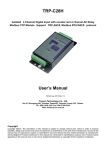
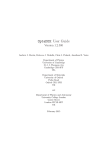
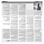
TRP-C68 8-Channel Analog Input to Digital Output Isolated Module Support ASCII and Modbus RTU protocol User’s Manual Printed Sep. 2013 Rev 1.4 Trycom Technology Co.,Ltd No.35, Zhongxing Rd., Guishan Township, Taoyuan County 333, Taiwan. Tel : 886-3-350-3351 Fax: 886-3-350-3352 Web: www.trycom.com.tw Copyright Copyright Notice: The information in this manual is subject to change without notice to improve reliability, design and function and does not represent a commitment on the part manufacturer. No part of this manual may be reproduced, copied, or transmitted in any form, without prior written permission by the manufacturer. Products mentioned in this manual are mentioned for identification purposes only. In this manual, product names appearing may or may not be registered trademarks of their respective companies or copyright. 1. Introduction TRP-C68, an 8-channel Analog to Digital Converter (ADC), takes an analog input signal and converts the input into a digital output signal. It accepts analog input-a voltage or a current-and supports the sample rate in “Normal” or “Fast” mode. All channels feature screw terminals for convenient connection, All analog inputs are provided with isolation and surge protection to protect the module against high voltage spikes, as well as ground potential differences. TRP-C68 support both ASCII and Modbus protocol, with a full set of command, dual watch-dog, and auto reset function the module can be remote controlled by PC in ASCII or Modbus RTU protocol. 1-1. Features Support ASCII and Modbus RTU protocol. Photo Isolation 3750V between digital and analog. All channels can input analog signal by voltage or current. Baud rate from 1.2Kbps to 115.2Kbps. Surge protection on RS-485 interface. LED display to indicate power and communication. Dual Watchdog for hardware reset circuit and host operating status. External switch for hardware and module’s configuration. Support screw terminal, or external DC power supply. Wide input range DC power supply. 1-2. Specifications Resolution: 16 Bit Sample rate: Normal mode: 10 sample / sec (24 bit). Fast Mode: 60 sample / sec (16 bit). Bandwidth: Normal Mode: 15.72Hz. Fast Mode:/78.72Hz…fast. Zero drift: 0.03uV/C. Span drift: 25 ppm/C. Accuracy: Normal 0.1 or better. Fast: 0.5 or better. Analog Input range: Voltage: ± 10V, ± 5V,± 2.5V,± 1.25V,± 650mV. Current: +/-20 mA CMRR:92db min/50/60Hz. Analog input over voltage protection:± 35V. RS485 connector: Industrial plug-in screw terminal. Communication Interface: RS485,2 wires. 2 LED indicator: Power and communication. Transmission distance : 4000ft(1200M). Speed: From 1.2K to 115.2Kbps. Power consumption:1.2 Watt. Power requirement: DC input from +10 to 30 V. Operating Temperature: 0 to 60℃. Storage Temperature: -20 to 60℃. Humidity: 10-90%, Non-condensing. Dimension: 151mm X 75mm X 26mm. Weight: 398g. 1-3. Panel layout 3 1-4. Block Diagram 1-5. Pin Definitions VIN5+ Analog Input Channel 5+ VIN4- Analog Input Channel 4- VIN5- Analog Input Channel 5- VIN4+ Analog Input Channel 4+ VIN6+ Analog Input Channel 6+ VIN3- Analog Input Channel 3- VIN6- Analog Input Channel 6- VIN3+ Analog Input Channel 3+ VIN7+ Analog Input Channel 7+ VIN2- Analog Input Channel 2- VIN7- Analog Input Channel 7- VIN2+ Analog Input Channel 2+ DATA+ RS485 DATA+ VIN1- Analog Input Channel 1- DATA- RS485 DATA- VIN1+ Analog Input Channel 1+ DC 10~30V Input Voltage VIN0- Analog Input Channel 0- GND Input Voltage Ground VIN0+ Analog Input Channel 0+ DC 10~30V 1-6. Communication Wiring 4 2. Wire Connection for Digital Input 2-1. Wire Connection For Current Input 2-2. Wire Connection For Voltage Input 3. System Configuration Switch The TRP-C68 DIO and AIO support the Modbus RTU and ASCII communication protocol, It has a two pins external dip-switch that allow user to select protocol between Modbus RTU and ASCII. The dip-switch also provides “back to INIT” function when user forget the configuring information stored in EEPROM such as ID (RS-485 Module address), baud rate and data format. *TRP-C68 Default setting: ID Address: 01, Baud Rate: 9600, Analog Mode Type: 08, Checksum: Disable, Data Format: 00, All analog input channels: Enable, RS485 communication data format: N, 8, 1. 5 Modbus Protocol (Factory) Modbus Communication Protocol. Back to INIT for Modbus Step1. Adjust to “on off” position Step2. Reboot the system. ASCII Protocol ACSII communication protocol. Back to INIT for ASCII Step1. Adjust to “on on” position Step2. Reboot the system. *INIT: ID=00, Baud-Rate: 9600, Data format: 00, TT=08. RS485 communication protocol:N,8,1 * The INIT* mode: if you forgot the C68 ID or baud-rate before you adjusted, you can adjust the switch to INIT* mode then easy to get ID=00. 3-1. How to manually more positive voltage calibration Send command "$ID7"…....make sure the TRP-C68 8 CH. enable. Send command "~IDE0"….calibration enable. Send command "~IDE1"….set up the calibration enable. Send command "$ID8"........perform the Zero calibration. Send command "~IDE1".....set up calibration enable again. Send command "$ID9"... ….perform the full calibration. Send command "~IDE0"......calibration disable. 6 4. Function description Auto voltage calibration: The TRP-C68 will auto calibrate the voltage when power up. However user may also use voltage calibrating command to correct the voltage while the environment temperature is obvious difference, or the module was long period in idle. When the voltage must be calibrated by software command, it is necessary to reboot the module before calibration. Dual Watchdog: Module self watchdog: The module’s watchdog is a hardware reset circuit while working in harsh or noisy environment, the module may be down. The circuit may enable the module to continue working and never halt. Host watchdog: The host watchdog is a software function to monitor the module's output states. The purpose is to prevent the RS-485 network from communication problem or host halt due to unexpected situation. When the timeout interval expired, the module will turn all outputs to predefined safe value. This can prevent the controlled target from unexpected situation. 5. ASCII Command Description The TRP-C68 DIO and AIO support the ASCII communication protocol, the serial communication data format is Parity check: None, data Bit: 8, Stop bit: 1, baud rate can setting from 1200bps~115200bps. 5-1.Factory Setting ID Address: 01, RS485 communication protocol: 9600, 8, N, 1 AI Mode Type: ±10V Checksum: Disable. 5-2.Protocol Syntax Command Format:” Leading Code”+”ID Address”+”Command”+”CHK”+(cr) . Response Format:”Leading Code”+”ID Address”+”Data”+”CHK”+ (cr) . 5-3. How to Calculate the Check Sum 1. Calculate the ASCII sum of all characters of the command string except the character return. 2. Mask the sum of string with OFFH. Example: Send the command is “$06M”. Sum of string is “$”+”0”+”6”+”M”=“24H”+”30H”+” 4D“=“A1H”……The checksum and [CHK]=“A1”. Response string with checksum is :”A1“. 7 5-4. ASCII Command List Command List Function Description Page Index %IDNNTTBBDD(CHK)(cr) Set the module configuration 5-5 #ID(CHK)(cr) Read all analog input 5-9 #IDN(CHK)(cr) Read analog input from N channel 5-10 $ID2(CHK)(cr) Read the module’s configuration 5-11 $ID5(CHK)(cr) Read reset status 5-12 $ID6HL(CHK)(cr) Select analog input channel enable/disable 5-13 $ID7(CHK)(cr) Read analog channel enable/disable status 5-14 ~01EV(CHK)(cr) Set up the calibration enable/disable 5-15 $ID8(CHK)(cr) Perform zero calibration 5-16 $ID9(CHK)(cr) Perform full calibration 5-17 $IDRS(CHK)(cr) Perform software reset 5-18 $IDM(CHK)(cr) Read the module’s name 5-19 $IDF(CHK)(cr) Read the module’s firmware version and date 5-20 ~IDONN(CHK)(cr) Chang the module’s name 5-21 ~IDWENN(CHK)(cr) Enable watch dog and set up timeout value 5-22 ~IDWD(CHK)(cr) Disable watchdog 5-23 ~IDWR(CHK)(cr) Read watchdog timeout value 5-24 ~**(CHK)(cr) System stand by (Host ok!) 5-25 8 5-5.Set the module’s configuration *The module must be reboot, When you set up module’s configuration after. Command %IDNNTTBBDD(CHK)(cr) % First leading code Syntax ID Address of setting module from 00~FF(HEX) Description NN New address of setting from 00~FF(HEX) TT Analog input type setting BB New baud rate setting DD Data Format CHK Checksum (cr) Carriage return !ID(CHK)(cr) Command valid ?ID(CHK)(cr) Command Invalid Response 5-6. (TT) Analog input type Type Code 08 09 0A 0B 0C 0D Voltage: ±10V ±5V ±2.5V ±1.25V ±650mV ±20mA % of FSR ±100 % ±100 % ±100 % ±100 % ±100 % ±100 % Fast 2’S 0000~8000~FFFF 0000~8000~FFFF 0000~8000~FFFF 0000~8000~FFFF 0000~8000~FFFF 0000~8000~FFFF Mode complem ent Normal 000000~800000~ 000000~800000~F 000000~800000~F 000000~800000~F 000000~800000~F 000000~800000~F Mode FFFFFF FFFFF FFFFF FFFFF FFFFF FFFFF 5-7. (BB) Baud Rate Setting 9 5-8. (DD) Data format setting Bit 7 6 5 4 3 2 1 0 Engineer Unit Format Function Rejection Checksum Mode *0=60Hz *0:Disable *0=Normal 1=50Hz 1:Enable 1=Fast *00=Voltage 0 0 0 01=Percent 10=2’s Complement HEX Format Example: Send command:”%0003080600”, New ID=03, Analog input= ±10V, Baud Rate=9600, Checksum=Disable DD=00 , Response:”!03”. *If you turn on the system setting switch, the ID will become to “00”, Then send command read analog input CH-0 voltage “#030”, Response:” >03+07.63178”=+7.63178V / Unit: Voltage. Example: Send command:%00030B0501 Response:”!03, New ID=03, Analog input= ±1.25V, Baud Rate=4800, Checksum=Disable DD=01. Then send command read analog input CH-0 FSR of percent “#030”, Response:” >03+063.3626” =63.3626 % / Unit: %. Example: Send command:%0101080602 Response:”!01, New ID=01, Analog input= ±10V, Baud Rate=9600, Checksum=Disable, Normal mode, DD=02. Then send command read analog input CH-0 FSR of percent “#010”, Response:” >017FF99F / Unit: 2’s complement 3 Byte 000000~800000~FFFFFF. *TRPCOM utility is the utility for user to configure the module, the utility also with on-line RS485 modules scanning and searching function. You can find the utility in the TRP-C68 support CD which is bundled in TRP-C68 standard package. 10 5-9. Read all analog input Command #ID(CHK)(cr) # First leading code Syntax ID Address of setting module from 00~FF(HEX) Description CHK Checksum (cr) Carriage return Response !IDData0~7(CHK)(cr) Channel 0,1,2,3,4,5,6,7 Data ?ID(CHK)(cr) Command Invalid Example Send command:”#01” Read the all analog input channels data. IF TT=08 the data will be show Response: “>01+02.667+00.006+00.002+00.000+00.000+00.000+00.000+00.000”…..Show the channel 0~7 voltage between -10V~+10V. / Unit: Voltage 11 5-10. Read analog input from N channel Command Syntax Description Response #IDN(CHK)(cr) # First leading code ID Address of setting module from 00~FF(HEX) N Analog channel 0~7 CHK Checksum (cr) Carriage return !IDData(CHK)(cr) Data: Channel N data ?ID(CHK)(cr) Command Invalid Example: Send command:”#010” Read the analog input channel 0 value. Response: >01+03.82062 Channel 0=+3.82062. /Unit: Voltage 5-11. Read Module’s Configuration Command Syntax Description Response $ID2(CHK)(cr) $ First leading code ID Address of setting module from 00~FF(HEX) 2 Read module’s configuration CHK Checksum (cr) Carriage return !IDTTBD00(CHK)(cr) TT: Analog input type ?ID(CHK)(cr) BD: Baud rate type Command Invalid Example: Send command:”$012” …..Read module’s configuration. Response:!01080600 TT=08=-10V~+10V……. Refer 5-6 , Baud rate=06=9600…..Refer 5-7. 12 5-12. Read reset status Command Syntax Description Response $ID5(CHK)(cr) $ First leading code ID Address of setting module from 00~FF(HEX) 5 Read reset status CHK Checksum (cr) Carriage return !IDS(CHK)(cr) S=1 Reset S=0 No Reset ?ID(CHK)(cr) Command Invalid Example: Send command: ”$015”. Response: !011 1:Module have been reset. *If the module is system halt or detect abnormal voltage, the module will auto restart and flag of reset set up to “1” until use “$ID5”. 5-13. Select analog input channel enable/disable Command Syntax Description Response $ID6HL(CHK)(cr) $ First leading code ID Address of setting module from 00~FF(HEX) 6 Set up channel enable/disable HL H: Channel 4~7, CHK Checksum (cr) Carriage return !ID(CHK)(cr) Command valid ?ID(CHK)(cr) Command Invalid L: Channel 0~3 , 0:disable 1:enable Example: Send command:”$0160F”….Channel0~3 enable, Channel4~7 disable, Response: !01. 13 Then send command:”#01”……Read channel 0~7, Response:” +02.130+07.512-01.765-02.986+00.000+00.000+00.000+00.000, From channel 4~7 is disable. 5-14. Read analog input channel enable/disable status Command Syntax Description Response $ID7(CHK)(cr) $ First leading code ID Address of setting module from 00~FF(HEX) 7 Read analog input channel enable/disable status CHK Checksum (cr) Carriage return !IDHL(CHK)(cr) H: Channel 4~7 L: Channel 0~3 0:Channel disable 1:Channel Enable ?ID(CHK)(cr) Command Invalid Example: Send command:”$017”, Response: “!010F” Channel 4~7 disable, Channel 0~3 enable. 5-15. Set up the calibration Enable/Disable Command Syntax Description Response ~IDEV(CHK)(cr) $ First leading code ID Address of setting module from 00~FF(HEX) EV V=0 Disable CHK Checksum (cr) Carriage return !ID(CHK)(cr) Command valid ?ID(CHK)(cr) Return not enable calibration before calibration command V=1 Enable Example: Send command:”~01E1”, Response: “!01”…… Enable calibration. *Refer to paragraph 4 Function description before calibration. 5-16. Perform Zero Calibration 14 Command Syntax Description Response $ID8(CHK)(cr) $ First leading code ID Address of setting module from 00~FF(HEX) 8 Perform zero calibration CHK Checksum (cr) Carriage return !ID(CHK)(cr) Command valid ?ID(CHK)(cr) Return not enable calibration before calibration command Example: Send command:”$018”, Response: “!01”. *Refer to paragraph 4 Function description before calibration. 5-17. Perform Full Calibration Command Syntax Description Response $ID9(CHK)(cr) $ First leading code ID Address of setting module from 00~FF(HEX) 9 Perform full calibration CHK Checksum (cr) Carriage return !ID(CHK)(cr) Command valid ?ID(CHK)(cr) Return not enable calibration before calibration command Example: Send command:”$019”, Response: “!01”. *Refer to paragraph 4 Function description before calibration. 5-18. Perform software Reset 15 Example: Send command:”$01RS”…….Reset , Response:”!01”……… ………Have been reset. 5-19. Read the module’s name Example: Send command:$01M…Read the TRP-C68’s name , Response:”!01TRPC68”……. The module’s name is “TRPC68. 5-20. Read the module’s firmware version 16 Command Syntax Description Response $IDF(CHK)(cr) $ First leading code ID Address of setting module from 00~FF(HEX) F Read firmware CHK Checksum (cr) Carriage return !IDNNYYMMDD(CHK)(cr) NN: Module’s name YYMMDD: Release Date ?ID(CHK)(cr) Command Invalid Example: Send command:$01F…Read the module’s firmware version, Response:” !01C68M070407”……. The module’s version date is “07/04/2007”. 5-21. Change the module’s name Example: Send command:”~01Oabcdef”….. Change the module name become to “abcdef”, Response:”!01”……. . Command valid. Then send the command “$01M”…read the module name, Response:”!01abcdef”……. .The TRP-C68’s name is “abcdef”. 5-22. Enable watchdog and set the timeout value 17 Example: Send Command:”~01WEFF”….. Set the watchdog time for 25.5 Sec, Response:”!01”……. . Command valid, When module count to 25.5 Sec the watchdog will into safe mode, then PWR LED will flash, recount. if the host send “~**” before timeout, the watchdog will 5-23. Disable watchdog Example: Send Command:”~01WD”….. Watchdog disable. Response:”!01”……. . Command valid, System LED will stop flashing. 5-24. Read watchdog timeout value 18 Example: Send Command:”~01WR”…. Read watchdog timeout value, Response:” !01WD0F”……. . Command valid, set the watchdog timeout is “0F”..1.6 Sec. 5-25. System stand by (Host OK!) *If watchdog is in enable, send the “Host Ok!” before watchdog timeout (B) the watchdog will re-count, PWR LED will flashing after watchdog timeout. 6. Modbus/RTU Command Description 19 The TRP-C68 AIO support Modbus/RTU protocol, The serial communication data format is Start bit: 1, Data bit: 8, Parity check: None, Stop bit: 1, Baud-rate: 1200bps~115200bps. 6-1. Modbus Syntax Command Format :ID(HEX)+FC(HEX)+SU(HEX)+DA(HEX) or RC(HEX)+CRC16(HEX), Response Format : ID(HEX)+FC(HEX)+SU(HEX)+DA(HEX) or RC(HEX)+CRC16(HEX), Error Format: ID(HEX)+ FC(HEX)+ CRC16(HEX). ID: RS485 Device Address (HEX)…..1~247 1Byte, FC: Function Code (HEX)…1 Byte, SU: Sub Function (HEX)…..1 Byte, DA: Data Format….No Limit, RC: Reserved code…No Limit, CRC: Cyclic Redundancy Check…2 Byte. *Error Response: If CRC IS mismatches error the response is empty! 7. Modbus/RTU Command List 20 Command List Function Description Index ID 46 00 00 (CRC) Read the module’s name 7-1 ID 46 04 IP 00 00 00 (CRC) Set up the module’s address 7-2 ID 46 05 00 (CRC) Read the module’s configuration 7-3 ID 46 06 00 BD 00 TT 00 DF 00 00 (CRC) Set up the module’s configuration 7-4 ID 46 07 00 (CRC) Read the module’s Firmware 7-5 ID 46 08 00 (CRC) Read the reset status 7-6 ID 46 09 00 (CRC) Set up the module reset 7-7 ID 46 21 HL 00(CRC) Select analog channel Disable/Enable 7-8 ID 46 22 00 (CRC) Read all channel Disable/Enable status 7-9 ID 46 25 XX 00 (CRC) Perform Spam Calibration 7-10 ID 46 26 00 (CRC) Perform Zero Calibration 7-11 ID 46 27 00 (CRC) Perform full Calibration 7-12 ID 03 00 NN 00 CN (CRC) Read one or multi channel analog input data 7-13 ID 04 00 NN 00 CN (CRC) Read one or multi channel analog input data 7-13 21 7-1.Read the module’s name Command Syntax Description ID 46 00 00 (CRC) ID Address of setting module 01~247 46 Function code 00 Read module’s name 00 Reserved code ID 46 00 00 ….Module command Line ID 46 00 00 0C 68 00 (CRC) 0C 68 :Module’s Name is C68 Response ID C6 00 (CRC) ID C6 (CRC) C6:Error function code 00 : Reserved code Example: Send Command:”01 46 00 00”…….Read the TRP-C68’s name, Response:”01 46 00 00 0C 68 00 “……Module’s name is C68, Error Response: “01 C6 00 ”……Error code. 7-2. Set up the module’s address Command Syntax Description ID 46 04 IP 00 00 00 (CRC) ID Address of setting module 1~247 46 Function Code 04 Set up module’s ID IP New module’s ID 00 00 00 Reserved code ID 46 04 00 00 00 00 (CRC) ID 46 04 00 00 00 00 ….Command valid. ID C6 00 (CRC) ID C6 (CRC) C6:Error function code 00 : Reserved code Response Example: Send Command:”01 46 04 02 0 0 0”…….Set up the new ID is “02”, Response:” 01 46 04 00 00 00 00 “……New ID changes to 02 , Error Response: “01 C6 00”……Error code. 22 7-3. Read the module’s configuration Command ID 46 05 00 (CRC) Syntax Description Response ID Address of setting module 1~247 46 Function Code 05 Read module’s configuration 00 Reserved code ID 46 05 00 BD 00 TT 00 DF 00 00 (CRC) ID 46 05 00 ……Module command Line BD: Baud-Rate….See 7-3-2 TT: Analog Input type….See 7-3-1 DF: Data format….See 7-3-3 ID C6 00 (CRC) ID C6 (CRC) C6:Error function code 00 : Reserved code 7-3-1. (TT) Analog input type Type Code 08 09 0A 0B 0C 0D Voltage: ±10V ±5V ±2.5V ±1.25V ±650mV ±20mA % of FSR ±100 % ±100 % ±100 % ±100 % ±100 % ±100 % 2’S complement 0000~8000~FFFF 0000~8000~FFFF 0000~8000~FFFF 0000~8000~FFFF 0000~8000~FFFF 0000~8000~FFFF HEX (HEX) (HEX) (HEX) (HEX) (HEX) 3 1 (HEX) 7-3-2. (BB) Baud Rate Setting 7-3-3. (DD) Data format setting Bit 7 6 5 4 2 0 Engineer Unit Format Function Rejection Checksum Mode *0=60Hz *0:Disable *0=Normal 1=50Hz 1:Enable 1=Fast *00=Voltage 0 0 0 01=Percent 10=2’s Complement HEX Format Example: 23 Send Command:”01 46 05 00”…Read TRP-C68’s configuration, Response:” 01 46 05 00 06 00 08 00 08 00 00 “ Error Response: “01 C6 00 ”……Error code . 7-4. Set up the module’s configuration Command Syntax Description ID 46 06 00 BD 00 TT 00 DF 00 00 (CRC) ID Address of setting module 1~247 46 Function Code 06 Set up module’s configuration 00 BD 00 TT 00 DF 00 00 BD: Baud-Rate….See 7-3-2 TT: Analog Input type….See 7-3-1 DF: Data format….See 7-3-3 ID 46 06 00 ……Module command Line ID 46 06 00 00 00 00 00 00 00 00 (CRC) 00 00 00 00 00 00 00 00 : Reserved code Response ID C6 00 (CRC) ID C6 (CRC) C6:Error function code 00 : Reserved code Example: Send Command:” 1 46 06 00 05 00 08 00 00 00 00”…….Set up TRP-C68’s configuration, Response:” 01 46 06 00 00 00 00 00 00 00 00 “…Command valid!, Error Response: “01 C6 ”……Error code, *Baud-Rate set to 4800 Analog input typ:+/-10V Data format:00. 24 7-5. Read the module’s Firmware Command Syntax Description ID 46 07 00 (CRC) ID Address of setting module 1~247 46 Function Code 07 Read module’s Firmware 00 Reserved code ID 46 07 YY MM DD 00(CRC) ID 46 20 ……Module command Line YY:Year, MM :Month ,DD:Date , 00 : Reserved code ID C6 00 (CRC) ID C6 (CRC) C6:Error function code 00 : Reserved code Response Example: Send Command:”01 46 07 00”…….Set up TRP-C68’s configuration, Response:” 01 46 07 07 04 07 00“…2007 /04/07 12.2006 TRP-C68 Firmware Version, Error Response: “01 C6 00 ”……Error code. 7-6.Read the reset status Command Syntax Description ID 46 08 00 (CRC) ID Address of setting module 01~247 46 Function code 08 Read reset status 00 Reserved code ID 46 08 00 ….Module command Line ID 46 08 XX 00 (CRC) XX=01 Have been reset , Response ID C6 00 (CRC) 00:Have been read ID C6 (CRC) C6:Error function code 00 : Reserved code Example: Send Command:”01 46 08 00”…….Read the TRP-C68’s reset status, Response:”01 46 08 01 00 “……Have been reset, Error Response: “01 C6 00 ”……Error code. 25 7-7.Set up the module reset Command Syntax Description Response ID 46 09 00 (CRC) ID Address of setting module 1~247 46 Function Code 09 Module Reset 00 Reserved code ID 46 09 00 (CRC) Module reset ID C6 00 (CRC) ID C6 (CRC) C6:Function Code 00: Reserved code Example: Send Command:”01 46 09 00”, Response:”01 46 09 00...Command valid, Error Response: “01 C6 00”…Error code. 7-8. Select analog channel Disable/Enable Command Syntax Description ID 46 21 HL 00 (CRC) ID Address of setting module 1~247 46 Function Code 21 Read module’s Firmware HL H: Channel 4~7 0:Channel disable 00 Reserved code ID 46 21 NN 00(CRC) Command valid ID C6 00 (CRC) ID C6 (CRC) C6:Error function code 00 : Reserved code L: Channel 0~3 1:Channel Enable Response Example: Send Command:”01 46 21 0F 00”……Enable Channel 0~3, Disable Channel 4~7, Response:” 01 46 21 0F 00 “…Command Valid, Error Response: “01 C6 00 ”……Error code. 26 7-9. Read all channel Disable/Enable status Command Syntax Description ID 46 22 00 (CRC) ID Address of setting module 1~247 46 Function Code 22 Read all channel disable/enable status 00 Reserved code ID 46 22 ……Module command Line Response ID 46 22 HL 00 (CRC) HL=Channel 0~F enable/disable status 00 : Reserved code ID C6 00 (CRC) ID C6 (CRC) C6:Error function code 00 : Reserved code Example: Send command :”01 46 22 00”…..Data Channel, Response:” 01 46 22 0F 00”…Channel 0~3 is enable, Channel 4~7 is disable, Error Response: “01 C6 00 ”……Error code. 7-10. Perform Spam Calibration Command Syntax Description ID 46 25 XX 00 (CRC) ID Address of setting module 1~247 46 Function Code 25 Spam calibration enable XX XX=00 Disable XX=01 Enable 00 Response Reserved code ID 46 25 00 00 (CRC) ID 46 25 00 ……Module command Line 00 : Reserved code ID C6 00 ID C6 (CRC) C6:Error function code00 : Reserved code (CRC) Example: Send command ”01 46 25 01 00”, Response:” 01 46 25 00”…Set up enable, Error Response: “01 C6 00”……Error code. *Refer to paragraph 4 Function description before calibration. 27 7-11. Perform Zero Calibration Command Syntax Description ID 46 26 00 (CRC) ID Address of setting module 1~247 46 Function Code 26 Spam zero calibration 00 Reserved code ID 46 26 ……Module command Line Response ID 46 26 00 (CRC) ID C6 00 00 : Reserved code (CRC) ID C6 (CRC) C6:Error function code 00 : Reserved code Example: Send command :”01 46 26 00”, Response:” 01 46 26 00”….Command valid, Error Response: “01 C6 00 ”……Error code. *Refer to paragraph 4 Function description before calibration. 7-12. Perform full Calibration Command Syntax Description ID 46 27 00 (CRC) ID Address of setting module 1~247 46 Function Code 27 Spam full calibration 00 Response Reserved code ID 46 27 00 (CRC) ID 46 27 ……Module command Line 00 : Reserved code ID C6 00 ID C6 (CRC) C6:Error function code 00 : Reserved code (CRC) Example: Send command :”01 46 27 00”, Response:” 01 46 27 00”….Command valid, Error Response: “01 C6”……Error code. *Refer to paragraph 4 Function description before calibration. 28 7-13. Read one or multi channel analog input data Command Syntax Description ID 03 00 NN 00 CN (CRC) ID 04 00 NN 00 CN (CRC) ID Address of setting module 1~247 03 or 04 Function Code 00 NN Start channel from NN=00~07 00 CN How many channel want to read CN=1~8 ID 03/04 BC ST DATA (CRC) ID 03 or 04 ……Module command Line BC: Byte Counter ST:01…when Voltage or % of FSR is Positive ST:00…. when Voltage or % of FSR is Negative ST:02…..when fast mode and engineer mode is 2byte ST:03…..when normal mode and engineer mode is 3byte DATA: Analog Input value Response ID 83 :Function Code ER=00 Syntax error ID 83 ER (CRC) ER=01 Data Format error ER=02 Start channel error ER=03 I/O out of range Example: TT=08, DF:00 Send command “1 3 0 0 0 1”…Read channel 0 voltage Response:” 01 03 05 10 00 87 89 65 “.......+8.78965V. *When voltage or % of FSR mode the data length is 5 byte, 1st byte is 10: Positive,00: Negative Example: When DF is 02 (Engineer and normal mode) ,Byte Counter is 3 bytes . TT=08, DF:02 DF: fast mode display 3 byte, Send command “01 03 00 00 01 “…Read channel 0 engineer mode :0000~8000~FFF /HEX= -10V~0V~+10V Response:” 01 03 03 B7 BD DB “....10: Engineer mode AC 1A =about +4.3V When DF is 22 (Engineer And fast Mode)..Byte Counter Is 2 Bytes TT=08, DF:22 DF: fast mode display 2 byte, Send command “01 03 00 00 01 “…Read channel 0 engineer mode :0000~8000~FFF /HEX= -10V~0V~+10V Response:” 01 03 02 AC 1A “....10: Engineer mode AC 1A =about +3.3V Example: TT=08, DF:02 DF: normal mode display 3 byte, Engineer Mode Send command “01 03 00 00 01 “…Read channel 0 engineer mode :000000~800000~FFFFF 29 /HEX= -10V~0V~+10V Response:” 01 03 03 EE 1C BD “....10: Engineer mode EE 1C BD =about +8.58V Example: TT=09, DF:01 Send command “01 46 06 00 06 00 09 00 01 00 00”….BD=9600,TT=09=+/-5V,DF=01 =% of FSR……set up configuration …see 7.4 Response:” 01 46 06 00 00 00 00 00 00 00 00” Send command “01 03 00 00 01 “…Read channel 0 % of FSR Response:” 01 03 05 10 00 51 43 59 “....51 43 59= + 51.4359 %......about +2.55V Example: Send command :”01 03 00 00 00 08”…..Read all channel, Response:” 01 03 28 00 00 02 27 97 00 00 00 00 61 10 00 00 01 22 00 00 00 00 61 10 00 00 00 00 10 00 00 00 00 10 00 00 00 00 10 00 00 00 00 ” Voltage/ Unit . Data format=00 Note: Some Modbus utility support 2 byte data each channel like Modbus Poll , but the TRP-C68 standard mode is support 5 byte for display , If user use the that utility ,the TRP-C68 must be adjust the data format . Example : Send command: “02 46 06 00 06 00 08 00 02 00 00”….Set the BD=06=9600, TT=08=+/-10V, DF=02=Engineer display. Response: “02 46 06 00 00 00 00 00 00 00 00”……Command valid. Then send the command : “1 3 0 0 0 1”……Read channel 0 voltage Response:” 02 03 02 E1 C1” ….Channel 0 data is =”E1 C1” Note: The engineer’s display is 0000(hex)~8000(hex)~FFFF(hex)=-10V~0V~+10V Example: TT=09, DF:01 Send command “01 46 06 00 06 00 09 00 01 00 00”….BD=9600,TT=09=+/-5V,DF=01 =% of FSR……set up configuration …see 7.4 Response:” 01 46 06 00 00 00 00 00 00 00 00” Send command “01 03 00 00 01 “…Read channel 0 % of FSR Response:” 01 03 05 10 00 51 43 59 “....51 43 59= + 51.4359 %......about +2.55V Example: TT=08, DF=00 Send command “01 03 00 05 0 3 “…Read channel 5~7 30 Response:” 01 03 0F 10 00 79 88 53 10 00 00 14 35 10 00 19 37 00 “….Channel 5=+7.98853V, Channel 6=+0V, Channel 7=+1.937V 7. How to use the utility for windows The TRPCOM utility can help you to test and configuration the module’s data transmit and receive analog input data and output communication status. User may download TRPCOM software from TRYCOM web www.trycom.com.tw. 1.The “Setting”function is for user to initiate the software to set the Com Port from 1 to 20 and setting the Baud-Rate from 1200 to 115200,Checksum Enable or Disable. …See Figure 1 *The Module Factory Setting is “9600” and “ID” is 01, Checksum is Disable. *Turn module’s switch to “OFF,ON” position into ASCII communication mode. Figure 1 2.The “Terminal” function is for user to input command, user can control all of module’s digital input/output status or wait to get module response status …See Figure 2. 31 Figure 2 If you don’t know the module’s ID may select “Scan” to find the module’s setting. 32 Select the module which one you want setting then click “Configuration”. Example: TRP-C68 Configuration A: Get analog input voltage Value please click “D0~D7” button. B: Set up new RS485 ID, Baud-Rate and data format then click “Write to EEPROM” button. 33 8.Application 9. Using the Modbus poll for test the TRP-DIO and AIO The Modbus poll is the very popular utility that supports the Modbus RTU/ASCII and Modbus TCP/IP, you can download that for test the any TRP-DIO and AIO basic Modbus function. The download website is http://www.modbustools.com/modbus_poll.asp 34