1
User’s Manual
FF
AP4, Application Leading Tool, Applilet3
Common Operations
User's Manual
Target Devices
RX Family
RL78 Family
RZ Family
Rev.1.00
Mar 2015
Notice
1.
Descriptions of circuits, software and other related information in this document are provided only to illustrate the operation of
semiconductor products and application examples. You are fully responsible for the incorporation of these circuits, software,
and information in the design of your equipment. Renesas Electronics assumes no responsibility for any losses incurred by you
or third parties arising from the use of these circuits, software, or information.
2.
Renesas Electronics has used reasonable care in preparing the information included in this document, but Renesas Electronics
does not warrant that such information is error free. Renesas Electronics assumes no liability whatsoever for any damages
incurred by you resulting from errors in or omissions from the information included herein.
3.
Renesas Electronics does not assume any liability for infringement of patents, copyrights, or other intellectual property rights of
third parties by or arising from the use of Renesas Electronics products or technical information described in this document. No
license, express, implied or otherwise, is granted hereby under any patents, copyrights or other intellectual property rights of
Renesas Electronics or others.
4.
You should not alter, modify, copy, or otherwise misappropriate any Renesas Electronics product, whether in whole or in part.
Renesas Electronics assumes no responsibility for any losses incurred by you or third parties arising from such alteration,
modification, copy or otherwise misappropriation of Renesas Electronics product.
5.
Renesas Electronics products are classified according to the following two quality grades: “Standard” and “High Quality”. The
recommended applications for each Renesas Electronics product depends on the product’s quality grade, as indicated below.
“Standard”:
Computers; office equipment; communications equipment; test and measurement equipment; audio and visual
equipment; home electronic appliances; machine tools; personal electronic equipment; and industrial robots etc.
“High Quality”: Transportation equipment (automobiles, trains, ships, etc.); traffic control systems; anti-disaster systems; anticrime systems; and safety equipment etc.
Renesas Electronics products are neither intended nor authorized for use in products or systems that may pose a direct threat to
human life or bodily injury (artificial life support devices or systems, surgical implantations etc.), or may cause serious property
damages (nuclear reactor control systems, military equipment etc.). You must check the quality grade of each Renesas
Electronics product before using it in a particular application. You may not use any Renesas Electronics product for any
application for which it is not intended. Renesas Electronics shall not be in any way liable for any damages or losses incurred
by you or third parties arising from the use of any Renesas Electronics product for which the product is not intended by Renesas
Electronics.
6.
You should use the Renesas Electronics products described in this document within the range specified by Renesas Electronics,
especially with respect to the maximum rating, operating supply voltage range, movement power voltage range, heat radiation
characteristics, installation and other product characteristics. Renesas Electronics shall have no liability for malfunctions or
damages arising out of the use of Renesas Electronics products beyond such specified ranges.
7.
Although Renesas Electronics endeavors to improve the quality and reliability of its products, semiconductor products have
specific characteristics such as the occurrence of failure at a certain rate and malfunctions under certain use conditions. Further,
Renesas Electronics products are not subject to radiation resistance design. Please be sure to implement safety measures to
guard them against the possibility of physical injury, and injury or damage caused by fire in the event of the failure of a Renesas
Electronics product, such as safety design for hardware and software including but not limited to redundancy, fire control and
malfunction prevention, appropriate treatment for aging degradation or any other appropriate measures. Because the evaluation
of microcomputer software alone is very difficult, please evaluate the safety of the final products or systems manufactured by
you.
8.
Please contact a Renesas Electronics sales office for details as to environmental matters such as the environmental compatibility
of each Renesas Electronics product. Please use Renesas Electronics products in compliance with all applicable laws and
regulations that regulate the inclusion or use of controlled substances, including without limitation, the EU RoHS Directive.
Renesas Electronics assumes no liability for damages or losses occurring as a result of your noncompliance with applicable laws
and regulations.
9.
Renesas Electronics products and technology may not be used for or incorporated into any products or systems whose
manufacture, use, or sale is prohibited under any applicable domestic or foreign laws or regulations. You should not use
Renesas Electronics products or technology described in this document for any purpose relating to military applications or use
by the military, including but not limited to the development of weapons of mass destruction. When exporting the Renesas
Electronics products or technology described in this document, you should comply with the applicable export control laws and
regulations and follow the procedures required by such laws and regulations.
10. It is the responsibility of the buyer or distributor of Renesas Electronics products, who distributes, disposes of, or otherwise
places the product with a third party, to notify such third party in advance of the contents and conditions set forth in this
document, Renesas Electronics assumes no responsibility for any losses incurred by you or third parties as a result of
unauthorized use of Renesas Electronics products.
11. This document may not be reproduced or duplicated in any form, in whole or in part, without prior written consent of Renesas
Electronics.
12. Please contact a Renesas Electronics sales office if you have any questions regarding the information contained in this document
or Renesas Electronics products, or if you have any other inquiries.
(Note 1) “Renesas Electronics” as used in this document means Renesas Electronics Corporation and also includes its majorityowned subsidiaries.
(Note 2) “Renesas Electronics product(s)” means any product developed or manufactured by or for Renesas Electronics.
(2012.4)
Terminology
The meanings of the terms used in this manual are described in the table below.
Term
Meaning
Renesas environment
An environment in which program development is conducted by using language
tools and an integrated development environment platform made by Renesas
Electronics Corporation.
GNU environment
An environment in which program development is conducted using Gcc.
IAR environment
An environment in which program development is conducted by using language
tools and an integrated development environment platform made by IAR Systems.
RL78-series AP4
AP4 for RL78-family
RX-series AP4
AP4 for RX-family
RZ-series AP4
AP4 for RZ-family
Related Documents
Please use the following documents in conjunction with this manual.
The related documents listed below may include preliminary versions. However,
preliminary versions are not marked as such.
Documents Related to Development Tools (User’s Manuals)
Document Name
Document Number
English
Japanese
RX Family User’s Manual :Software
R01US0032J
R01US0032E
RL78 Family User’s Manual :Software
R01US0015J
R01US0015E
Caution
The related documents listed above are subject to change without notice. Be sure to use
the latest version of each document for designing, etc.
R20UT3420EJ0100 Rev1.00
Mar 31, 2015
Page 3 of 48
I
CONTENTS
Chapter 1 Outline .................................................................................................................................................. 6
1.1 Overview.................................................................................................................................................. 6
1.2 Names and Functions of Hardware ......................................................................................................... 6
1.3 Functions ................................................................................................................................................. 7
Chapter 2 Installation ............................................................................................................................................ 8
2.1 Features of Installer ................................................................................................................................. 8
2.2 Installation Procedure .............................................................................................................................. 8
2.3 Uninstallation Procedure ....................................................................................................................... 11
Chapter 3 Operating Procedure ......................................................................................................................... 12
3.1 Names of Parts ...................................................................................................................................... 12
3.1.1 Title Bar ....................................................................................................................................... 13
3.1.2 Menu Bar ..................................................................................................................................... 13
3.1.3 Main Toolbar ............................................................................................................................... 13
3.1.4 Module Toolbar ........................................................................................................................... 13
3.1.5 Status Bar.................................................................................................................................... 13
3.1.6 Project Tree Panel ...................................................................................................................... 14
3.1.7 Module Panel .............................................................................................................................. 14
3.1.8 Preview Panel ............................................................................................................................. 15
3.1.9 Property Panel ............................................................................................................................ 15
3.1.10 Output Panel ............................................................................................................................. 15
3.2 Operating Procedure ............................................................................................................................. 16
3.3 Starting up ............................................................................................................................................. 17
3.4 Creating a New Project File ................................................................................................................... 18
3.5 Opening an Existing Project .................................................................................................................. 19
3.6 Setting up a Peripheral Function ........................................................................................................... 20
3.6.1 Input Conventions ....................................................................................................................... 21
3.6.2 Icon Display on Invalid Input Fields ............................................................................................ 21
3.6.3 Icon Display on Pin Contention ................................................................................................... 22
3.7 Checking Source Code ......................................................................................................................... 23
3.7.1 Setting Output on/off ................................................................................................................... 24
3.7.2 Renaming a File .......................................................................................................................... 25
3.7.3 Renaming an API Function ......................................................................................................... 26
3.8 Output of Source Code .......................................................................................................................... 27
3.8.1 Modifying the Output Modes ....................................................................................................... 28
3.8.2 Changing Output Destinations .................................................................................................... 29
3.9 Generating a Report File ....................................................................................................................... 30
3.10 Saving a Project .................................................................................................................................. 31
3.11 Closing ................................................................................................................................................. 32
3.12 Coding ................................................................................................................................................. 32
R20UT3420EJ0100 Rev1.00
Mar 31, 2015
Page 4 of 48
Chapter 4 Menu Reference ................................................................................................................................ 33
4.1 [File] Menu ............................................................................................................................................. 33
4.2 [Peripheral Functions] Menu ................................................................................................................. 34
4.3 [Options] Menu ...................................................................................................................................... 35
4.4 [Help] Menu ........................................................................................................................................... 36
4.5 Toolbars ................................................................................................................................................. 37
4.5.1 Main Toolbar ............................................................................................................................... 37
4.5.2 Module Toolbar ........................................................................................................................... 38
Chapter 5 Window Reference ............................................................................................................................ 39
5.1 Project Tree Panel ................................................................................................................................. 39
5.2 Module Panel......................................................................................................................................... 40
5.2.1 Example of a Module Panel for Clock Generation Circuits ......................................................... 41
5.2.2 Example of a Module Panel for Ports ......................................................................................... 42
5.2.3 Example of a Module Panel for a Peripheral Function (1 Channel) ........................................... 43
5.2.4 Example of a Module Panel for a Peripheral Function (Multiple Channels) ............................... 44
5.2.5 Example of a Module Panel for a Peripheral Function (1 Unit)................................................... 45
5.3 Preview Panel........................................................................................................................................ 46
5.4 Output Panel.......................................................................................................................................... 48
R20UT3420EJ0100 Rev1.00
Mar 31, 2015
Page 5 of 48
AP4, Application Leading Tool, Applilet3 Common Operations
User's Manual
Chapter 1 Outline
1.1 Overview
The AP4 and Application Leading Tool(Applilet) is a software tool that automatically generates device drivers for the
RL78 microcontroller and the RX microcontroller made by Renesas Electronics. The Applilet consistent with the device
to be employed should be used.
Through the GUI, the Apllilet allows you to quickly initialize peripheral module registers.
This manual provides common operation specifications, such as the Applilet main window, menus, and dialog
operating methods, which are not dependent on the specific device to be employed.
This manual provides explanations by using RX111 Applilet screens as examples.
1.2 Names and Functions of Hardware
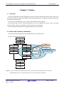
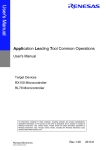
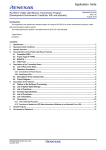
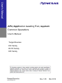
The flowchart of developmental tasks using the Applilet is shown in the figure below.
Figure 1-1 Developmental Flowchart
Product Planning
System Design
Software Design
Software Design
Implement
Coding
Applilet
Edit
e2 studio
IAR Embedded WorkbenchTM
Compile /
Assemble
Test
Build
CS+
Debug
Debug
System Debug
System Test
commodification
Remark: e2 studio: An eclipse-based integrated development environment provided by Renesas Electronics Corporation
IAR Embedded Workbench: An integrated development environment provided by IAR Systems
R20UT3420EJ0100 Rev1.00
Mar 31, 2015
Page 6 of 48
AP4, Application Leading Tool, Applilet3 Common Operations
User's Manual
1.3 Functions
○
Outputting device drivers
According to the parameters that are set through the GUI, the Applilet automatically generates, in a file, the
source code that initializes peripheral functions. File names can be changed as desired.
○
Providing API functions
In addition to peripheral function initialization code, the Applilet provides API functions, such as starting and
stopping a peripheral function or modifying the conditions.
API function names can be changed as desired.
○
Selecting a build tool
The type of a build tool (compiler) can be selected from gcc and IAR.
The Applilet outputs the workspace/project file for the integrated development environment platform that matches
the selected build tool.
• Renesas environment: Link directive file (.dr) for the C compiler
• IAR environment: Project Connection file for IAR Embedded Workbench (.icpf)
2
• GNU environment: e studio project file
○
Merging
●
Merging source codes
Programs written between the merge comments can be retained without deletion during the re-output
(overwriting) of the code.
●
Merging workspace/project files
The Applilet stores output files as target files to be built in a workspace/project file in the integrated development
environment platform. During code regeneration, the Applilet changes the storage of target build files as the
number of files that are output by the Applilet increases or decreases*. In such a case, any previously stored
user files are retained without being deleted.
* The Applilet stores files on an add-on basis, but it does not delete files that are no longer needed.
○
Outputting report
Reports on peripheral function settings, API function names associated with the various functions, and file names
can be output in a file. As the format of an output file, either HTML or CSV can be selected.
R20UT3420EJ0100 Rev1.00
Mar 31, 2015
Page 7 of 48
AP4, Application Leading Tool, Applilet3 Common Operations
User's Manual
Chapter 2 Installation
2.1
Features of Installer
The Applilet Installer has the features described below.
○
Accommodating multiple versions
Multiple versions of the Applilet can be installed on a single PC.
○
A common package handling both English and Japanese environments
The Installer does not automatically distinguish languages. At the beginning of the installation process, the user
should select a desired language.
Even in Japanese-version Windows, if the Applilet is installed after selecting [English], the Installer can install the
version of the Applilet that displays items in English.
Caution: The Applilet is used as a single application.
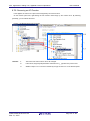
2.2
Installation Procedure
This section describes the procedure for installing the Applilet, taking the installation of [AP4 for RX111] in Windows 7
as an example. The contents of display may vary depending upon the particular operating system and software being
used.
Cautions
1.
2.
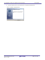
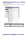
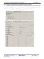
You need to perform installation by logging in as a user with Administrator privileges.
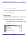
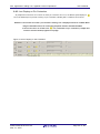
For the execution of the Applilet, you need to install “.NET Framework Version 4” as well as the
“Microsoft Visual C++ 2010 SP1” run-time library. If these files have not already been installed
on the host machine being used, install the files by downloading them from Microsoft
Corporation’s website.
Whether these files have been previously installed can be checked by viewing [Add or Remove
Programs] in Windows.
Figure 2-1 Add or Remove Programs (Verifying .NET Framework Version 4.0)
R20UT3420EJ0100 Rev1.00
Mar 31, 2015
Page 8 of 48
AP4, Application Leading Tool, Applilet3 Common Operations
User's Manual
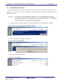
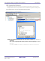
(1) Using the Applilet installer, execute the [Setup.exe] file.
Remarks 1. The Applilet installer can be acquired from the website for Renesas Electronics.
http://www.renesas.com/products/tools/coding_tools/coding_assistance/applilet/
(The address of the website is subject to change without notice.)
2.
The downloaded installer may be compressed. If it is compressed, decompress it and execute the
[Setup.exe] file.
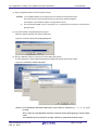
(2) The [Choose Setup Language] dialog box appears.
Select the desired language, and click the [OK] button.
Figure 2-1 [Choose Setup Language] Dialog Box
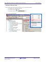
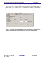
(3) Specify installation settings according to the wizard dialog that appears.
In each dialog box, clicking either the [Next] or [Yes] button brings up the next screen.
Figure 2-2 Installation Wizard Dialog Box
Caution: In the installation destination folder name, none of these 11 characters, [( / * : < > ? | ” ¥ ; ,] can
be used.
Also, a space (a single-byte blank character) cannot be used at the beginning or end of a folder
name.
The installation process may fail if an illegal character is specified in the folder name.
R20UT3420EJ0100 Rev1.00
Mar 31, 2015
Page 9 of 48
AP4, Application Leading Tool, Applilet3 Common Operations
User's Manual
(4) To end the installation process, click the [Finish] button on the [Wizard Completed] screen.
Figure 2-3 [Wizard Completed] Screen
R20UT3420EJ0100 Rev1.00
Mar 31, 2015
Page 10 of 48
AP4, Application Leading Tool, Applilet3 Common Operations
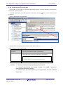
2.3
User's Manual
Uninstallation Procedure
This section describes the procedure for uninstalling the Applilet, taking the uninstallation of Applilet for RX111 in
Windows 7 as an example. The contents of display may vary depending upon the particular operating system and
software being used.
Cautions 1.
2.
You need to perform uninstallation by logging in as a user with Administrator privileges.
Uninstalling the Applilet will not uninstall the “.NET Framework Version 4” and “Microsoft
Visual C++ 2010 SP1” run-time library and associated files.
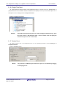
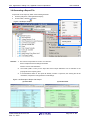
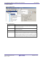
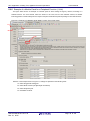
(1)In [Add or Remove Programs] of Windows 7, click the [Uninstall] button for the Applilet to be uninstalled.
Figure 2-4 Add or Remove Programs (Uninstalling Applilet)
(2)In the wizard dialog box that appears, select [Yes].
Figure 2-5 Confirming Uninstallation
(3)The uninstallation process finishes.
Figure 2-6 Uninstall Finished
R20UT3420EJ0100 Rev1.00
Mar 31, 2015
Page 11 of 48
AP4, Application Leading Tool, Applilet3 Common Operations
User's Manual
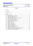
Chapter 3 Operating Procedure
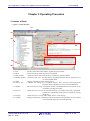
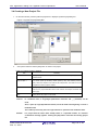
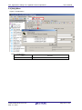
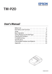
3.1 Names of Parts
Figure 3-1 Main Window
<1>
<2>
<3>
<9>
<4>
<7>
<6>
<8>
<9>
<8>
<5>
<10>
<1> Title
: Displays the product name and the Applilet project file name.
<2> Menu
: Allows the user to select and execute a command.
<3> Main Toolbar : Allows the user to select and execute a command by clicking a button.
<4> Module Toolbar: Generates code. Also, switches between peripheral functions that are displayed or set
up on the Module Panel.
<5> Status
: Displays information on the current project.
<6> Project Tree
: Indicates the settings for a peripheral function. Also, switches between peripheral
functions that are displayed or set up on the Module Panel.
<7> Module
: Allows the user to set up a peripheral function. The Module and Preview panels can be
switched by pressing the tab key.
<8> Preview
: Allows the user to set the file and API function to be output when code is generated.
The Preview and Module panels can be switched by pressing
the tab key.
<9> Property
: Allows the user to view or make output, macro, or file settings.
<10> Output
: Displays information, including the execution status of code generation or report output,
or the allowable range for a selected input field.
R20UT3420EJ0100 Rev1.00
Mar 31, 2015
Page 12 of 48
AP4, Application Leading Tool, Applilet3 Common Operations
User's Manual
3.1.1 Title Bar
The title bar displays the product name and the Applilet project file name. A project file name tagged with a “*”
indicates that the file does not contain the latest settings.
Figure 3-2 Title Bar
3.1.2 Menu Bar
The menu bar is used to select and execute a command. For the functions of the various menus, see Chapter
4 Menu Reference.
Figure 3-3 Menu Bar
3.1.3 Main Toolbar
Clicking a button on the main toolbar allows the user to execute frequently used functions. For button functions,
see 4.5.1 Main Toolbar.
Figure 3-4 Toolbar
3.1.4 Module Toolbar
Code generation can be executed by clicking the [
] button on the module toolbar. Also,
clicking a peripheral function button switches between peripheral functions that are displayed or set up on the
Module panel. For button functions, see 4.5.2 Module Toolbar.
Figure 3-5 Module Toolbar
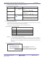
3.1.5 Status Bar
The status bar displays device information (the product series name and device name).
Figure 3-6 Status Bar
<1>
<2>
Remark: <1> Device product group name, <2> Applicable device name
R20UT3420EJ0100 Rev1.00
Mar 31, 2015
Page 13 of 48
AP4, Application Leading Tool, Applilet3 Common Operations
User's Manual
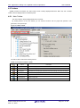
3.1.6 Project Tree Panel
This panel shows the settings status of each peripheral function in the form of an icon. Double-clicking a
peripheral function name switches between modules that are displayed or set up on the Module panel. For a
description of what is displayed, see 5.1 Project Tree Panel.
Figure 3-7 Project Tree Panel
Remark:
If the width of the Project Tree panel is too small to display all character strings, place
the mouse cursor on the character string or icon of interest. This will display all
character strings for an item on the tooltip.
3.1.7 Module Panel
This panel is used to set up a peripheral function. For the operating procedure, see 3.6 Setting up a
Peripheral Function.
Figure 3-8 Module Panel
Remark:
The positions of the Module panel and Preview panel can be switched by dragging
and dropping the tab.
R20UT3420EJ0100 Rev1.00
Mar 31, 2015
Page 14 of 48
AP4, Application Leading Tool, Applilet3 Common Operations
User's Manual
3.1.8 Preview Panel
This panel is used to set the file and the API function that are output during the code generation process. For
the operating procedure, see 3.7 Checking Source Code.
Figure 3-9 Preview Panel
3.1.9 Property Panel
This panel is used to view or make output, macro, and file settings.
For a description of what is displayed,
see 5-4 Property Panel.
Figure 3-10 Property Panel
3.1.10 Output Panel
This panel displays the execution status of code generation or report output, and information such as the
allowable range for a selected input field. For a description of what is displayed, see 5.4 Output Panel.
Figure 3-11 Output Panel
R20UT3420EJ0100 Rev1.00
Mar 31, 2015
Page 15 of 48
AP4, Application Leading Tool, Applilet3 Common Operations
User's Manual
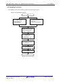
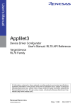
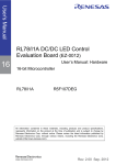
3.2 Operating Procedure
In the Applilet, source code is created by performing the following procedure:
Figure 3-12 Operating Procedure
Start
Create a project
・Select target device
・Select compiler
・Input project name
Open existing project
・Select File
・Select recently-used File
Specify Peripheral Function
・Select target peripherals
・Specify functions on the
d l
l ジ
Specify Code
・Input output or not
・Input file name
・Input API function name
Generate Code
・Set / marge output format
・Set output path
Generate Report
Save Project
End
R20UT3420EJ0100 Rev1.00
Mar 31, 2015
Page 16 of 48
AP4, Application Leading Tool, Applilet3 Common Operations
User's Manual
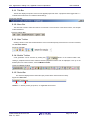
3.3 Starting up
This section explains how to start up the Applilet.
1. In Windows, select the [Start] button -> [Program] -> [Renesas Electronics Application Leading Tool] ->
[RX111] -> [Vx.xx.xx]. After these items are selected, the Applilet main window starts up.
Figure 3-13 Main Window (Immediately after the Startup)
R20UT3420EJ0100 Rev1.00
Mar 31, 2015
Page 17 of 48
AP4, Application Leading Tool, Applilet3 Common Operations
User's Manual
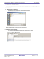
3.4 Creating a New Project File
1. On the main window, press the [New Project] button to display the [New Project] dialog box.
Figure 3-14 [New Project] Dialog Box
2.
Set up items and then click the [OK] button to create a new project.
Table 3-1 Project Creation Settings
Item
Microcontroller
Summary
Specify a target device. Peripheral functions that can be set up vary with the
specified device.
Using compiler *1
From CCRX (made by Renesas), EWRX (made by IAR), and GNURX (made by
KPIT), select the compiler to be used for the build process. The build tool can be
changed even after a project is created.
Project name
Specify a project folder/file name. If IAR Embedded Workbench is specified as the
build tool, the project folder/file name is also used as the Project Connection file
name (.icpf).
Place
Specify where the project is to be saved.
*1: The item which can be chosen changes with a micro controller.
Caution:
In a folder/file name, a single-byte alphanumeric character and "_" (underbar) can be
used.
Also, a space (a single-byte blank character) cannot be used at the beginning or end of a
folder/file name.
The creation process may fail if an illegal character is specified in the folder/file name.
Remark:
If a project with the same name already exists in a specified location, an overwrite
confirmation message appears. Clicking the [OK] button overwrites the existing project
file.
R20UT3420EJ0100 Rev1.00
Mar 31, 2015
Page 18 of 48
AP4, Application Leading Tool, Applilet3 Common Operations
User's Manual
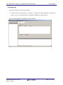
3.5 Opening an Existing Project
If a previously created project exists, it can be opened by either specifying the file name or by selecting it from a
list of recent projects.
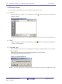
(1)Opening a file by selecting it
In the Main window, press the [File] button. The [Open] dialog box appears.
Figure 3-15 [Open] Dialog Box
Selecting the file and clicking the [Open] button opens the selected file.
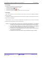
(2)Opening a recently used file
From the [Recent Projects] displayed in the Main window, select the file to be opened.
Figure 3-16 Opening a Recent Project
R20UT3420EJ0100 Rev1.00
Mar 31, 2015
Page 19 of 48
AP4, Application Leading Tool, Applilet3 Common Operations
User's Manual
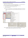
3.6 Setting up a Peripheral Function
Peripheral functions to be displayed on the Module panel can be selected by one of the methods listed below. For
a description of what is displayed on the Module panel, see 5.2 Module Panel.
●
From the [Peripheral Functions] menu in the Main window, select a peripheral function.
●
On the Tree View panel, double-click the peripheral function name.
●
Click the module toolbar button.
Remark: Even when the Module panel is not being displayed, the Module panel can be opened by
selecting a peripheral function from either the [Peripheral Functions] menu or the Tree View
panel.
Figure 3-17 Setting up a Peripheral Function
Figure 3-1 Example of Settings in the Module Panel (Clock Setting)
Caution: The [Clock setting] can affect other peripheral function settings. If the [Clock setting] is
modified, the settings for other peripheral functions need to be rechecked.
R20UT3420EJ0100 Rev1.00
Mar 31, 2015
Page 20 of 48
AP4, Application Leading Tool, Applilet3 Common Operations
User's Manual
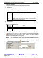
3.6.1 Input Conventions
Input of information into the Module panel is subject to the following conventions:
(1)Character set
Table 3-2 lists character sets that the Module panel can accept for input.
Table 3-2 List of Character Sets
Character set
Summary
ASCII
Single-byte alphabetic, numeric, and symbol characters
Shift-JIS
Double-byte alphabetic, numeric, symbol, hiragana, katakana, and kanji characters, and
single-byte katakana characters
EUC-JP
Double-byte alphabetic, numeric, symbol, hiragana, katakana, and kanji characters, and
single-byte katakana characters
UTF-8
Double-byte alphabetic, numeric, symbol, hiragana, katakana, or kanji (including Chinese)
characters, and single-byte katakana characters
(2)Numeric values
Table 3-3 shows radix base numbers that the Module panel can accept for input.
Table 3-3 List of Radix Base Numbers
Radix number
Summary
representation
Decimal
A number beginning with a numeral 1 to 9, followed by numerals 0 to 9, including 0.
Hexadecimal
A number beginning with 0x, followed by 0 to 9 or alphabetic characters a to f, (not casesensitive).
3.6.2 Icon Display on Invalid Input Fields
If an illegal character string is entered or if a value is not entered in a required field, the Module panel displays
a
icon indicating that the input data is incorrect. In addition, the Module panel represents the affected
character string in red to provide a warning that input is invalid.
Remarks
1.
If an invalid input field is present, control cannot move to another peripheral function
setup view.
2.
If the mouse cursor is moved to the
icon, information on the character string to be input (a
helpful hint on how to resolve the input error) is displayed as a popup.
Figure 3-18 Icon Display on Invalid Input Fields
R20UT3420EJ0100 Rev1.00
Mar 31, 2015
Page 21 of 48
AP4, Application Leading Tool, Applilet3 Common Operations
User's Manual
3.6.3 Icon Display on Pin Contention
As peripheral functions are set on items in which pin contention can occur, the Module panel displays a
icon in the affected spot to provide a warning on pin contention, indicating that a contention has occurred.
Remarks 1. The function for which a pin contention warning icon is displayed cannot be enabled. When
using the affected function, the contending peripheral function should be disabled.
If the mouse cursor is moved to the
icon, information on pin contention (a helpful hint
on how to avoid contention) appears as a popup.
Figure 3-19 Icon Display on Pin Contention
R20UT3420EJ0100 Rev1.00
Mar 31, 2015
Page 22 of 48
AP4, Application Leading Tool, Applilet3 Common Operations
User's Manual
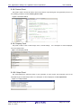
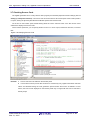
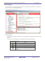
3.7 Checking Source Code
The Applilet generates source code (a device driver program) that matches peripheral function settings (see 3.6
Setting up a Peripheral Function). The source code can be checked on the Preview panel. If the Preview panel is
not open, clicking the [Preview] tab switches the Module panel to the Preview Panel.
On the tree on the Preview panel, double-clicking either the source code file name or the API function name
switches the display of the source code.
On the Preview panel tree, you can specify whether to turn on or off an output, rename API functions, or rename
files.
Figure 3-20 Verifying Source Code
Remarks
1.
Source code cannot be edited on the Preview panel.
2.
In some API functions (such as API functions for a serial array unit), register value SFRs and other
values are calculated during the code generation process before the function is finalized. For this
reason, the source code displayed on the Preview panel may not agree with the source code that is
actually output.
R20UT3420EJ0100 Rev1.00
Mar 31, 2015
Page 23 of 48
AP4, Application Leading Tool, Applilet3 Common Operations
User's Manual
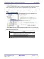
3.7.1 Setting Output on/off
According to the peripheral function settings, the Applilet automatically enables the output of a required API
function. For non-mandatory API functions, the user can enable/disable the output of the API function.
On the Preview panel tree, right-clicking the API function name brings up a context menu. By selecting
[Generate Code] / [Not Generate Code], the user can specify whether to turn on or off an output of the API
function.
Figure 3-21 Output on/off Settings
Remark: Whether output is on or off can be checked by the type of each icon on the Preview panel.
Table 3-4 Source Code Output on/off
Icon type
Summary
The source code for this API function will be output.
The API function for which this icon is displayed is treated as a function
requiring source code output (not changeable to a
).
The source code for this API function will be output.
The source code for this API function will not be output.
R20UT3420EJ0100 Rev1.00
Mar 31, 2015
Page 24 of 48
AP4, Application Leading Tool, Applilet3 Common Operations
User's Manual
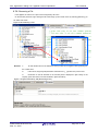
3.7.2 Renaming a File
In the Applilet, the code to be output can be assigned any file name.
On the Preview panel tree, right-clicking the file name brings up the context menu. By selecting [Rename], you
can edit the file name.
Figure 3-22 Renaming a File
{ XE "名前を変更する:ファイル名" ¥y "なまえをへんこうする" }{ XE "ファイル名:名前を変更する" }
Remarks
1.
To reset the file name to the default file name provided by the Applilet, select [Default] from
the context menu.
2.
In file names, single-byte alphanumeric characters and [ _ ] (underscore) can be used.
3.
Information on the file selected on the Preview panel is displayed in [File name] on the
Property panel. File names can also be edited in [File Information].
Figure 3-23 [File Information] Tab (Renaming a File)
R20UT3420EJ0100 Rev1.00
Mar 31, 2015
Page 25 of 48
AP4, Application Leading Tool, Applilet3 Common Operations
User's Manual
3.7.3 Renaming an API Function
In the Applilet, the code to be output can be assigned any API function name.
On the Preview panel tree, right-clicking the API function name brings up the context menu. By selecting
[Rename], you can edit the file name.
Figure 3-24 Renaming an API Function
Remarks
1.
The name of the main function cannot be changed.
2.
In file names, single-byte alphanumeric characters and [ _ ] (underscore) can be used.
3.
Whether output is on or off can be checked by the type of each icon on the Preview panel.
R20UT3420EJ0100 Rev1.00
Mar 31, 2015
Page 26 of 48
AP4, Application Leading Tool, Applilet3 Common Operations
User's Manual
3.8 Output of Source Code
Source code (a device driver program) can be output by any of the following methods:
-
From the [File] menu, select [Generate Code].
-
On the toolbar, click the [
-
On the module toolbar, click the [
] button.
]button
Figure 3-25 Code Generation
R20UT3420EJ0100 Rev1.00
Mar 31, 2015
Page 27 of 48
AP4, Application Leading Tool, Applilet3 Common Operations
User's Manual
3.8.1 Modifying the Output Modes
In the Applilet, you can select an output mode (overwriting, merging, or previous-file-priority) from [Generate
File Mode] on the Property panel.
To change output modes, in the [File generation control] field, click the
button to select a desired mode
from the list.
Figure 3-26 Changing Output Modes
{ XE "モード" }{ XE "出力モード" ¥y "しゅつりょくもーど" }
An output mode can be selected from the three modes listed in Table 3-5.
Table 3-5 Source Code Output Mode
Output mode
Overwrite file
Summary
If an identically named file already exists, overwrites that file.
Merge file
If an identically named file already exists, merges that file with the current file.
Only the content of a merge comment is subject to the merging action.
/* Start user code. Do not edit comment generated here */
[merge section]
/* End user code. Do not edit comment generated here */
Do nothing if file exists
Remarks
If an identically named file already exists, does not output the current file.
1.
The merge comment can vary depending on where it occurs.
2.
A merge comment should not be edited or moved. If it is edited or moved, the
merging cannot be performed correctly.
3.
The presence of any unpaired braces { } in a merge section can result in deleted
source code.
R20UT3420EJ0100 Rev1.00
Mar 31, 2015
Page 28 of 48
AP4, Application Leading Tool, Applilet3 Common Operations
User's Manual
3.8.2 Changing Output Destinations
In the Applilet, where source code is to be output can be specified in [Output folder] on the Property panel.
To change destination folders, an output destination folder can be selected on the [Browse For Folder] screen,
which is displayed when the
button in the destination folder field is clicked.
Figure 3-27 Specifying an Output Destination
{ XE "出力先" ¥y "しゅつりょくさき" }
Remark: In the installation destination folder name, none of these 11 characters, [( / * : < > ? | ” ¥ ; ,]
can be used.
Also, a space (a single-byte blank character) cannot be used at the beginning or end of a
folder name.
The output changing process may fail if an illegal character is specified in the folder name.
R20UT3420EJ0100 Rev1.00
Mar 31, 2015
Page 29 of 48
AP4, Application Leading Tool, Applilet3 Common Operations
User's Manual
3.9 Generating a Report File
A report file can be output by either of the following methods:
●
From the [File] menu, select [Generate Report].
●
On the toolbar, click the [
] button.
Figure 3-28 Report Output
{ XE "レポート出力" ¥y "れぽーとしゅつりょく" }
Remarks
1. The names of report files are “macro” and “function”.
macro: Peripheral function settings information
function: Source code information
2.
The format (HTML or CSV) for the report file and its output destination can be selected on the
[output] tab on the Property panel.
3.
If the destination folder for the report file already contains a report file, the existing file will be
overwritten, irrespective of file generation mode settings.
Figure 3-29 Example of Report File Output
(a) macro.html
R20UT3420EJ0100 Rev1.00
Mar 31, 2015
(b) function.html
Page 30 of 48
AP4, Application Leading Tool, Applilet3 Common Operations
User's Manual
3.10 Saving a Project
To save information that has been set, any of the following methods can be used:
(1)Save as
Select the [File] menu -> [Save As…]. Alternatively, click the [
]button on the toolbar, The [Save As]
dialog box appears.
Figure 3-30 [Save As] Dialog Box
To save the information that has been set, specify a destination and a file name, and click the [Save] button.
(2)Save
Select the [File] menu -> [Save]. Or on the toolbar, click the [
saved on an overwrite basis.
] button. The file (project) being edited is
(3)Close and save
When an attempt is made to exit from the Applilet without saving the modified settings, a save confirmation
dialog box appears.
Clicking the [Yes] button saves the file (project) being edited on an overwrite basis.
Clicking the [No] button skips the save process.
Figure 3-31 Question Dialog Box
Remark:
The name of the file to be saved (not including the extension) is identical to the Applilet project name.
R20UT3420EJ0100 Rev1.00
Mar 31, 2015
Page 31 of 48
AP4, Application Leading Tool, Applilet3 Common Operations
User's Manual
3.11 Closing
The Applilet can be closed by any of the following methods:
-
On the Main window, select the [File] menu -> [Exit].
-
On the toolbar, click the [
-
On the Main window, click the [
-
On the menu that appears when an icon on the title bar is clicked, select [Close].
] button.
] button.
3.12 Coding
After code is generated, the source code that has been output is read using the integrated development
environment platform.
The program is completed by adding user source files as necessary or adding code in the merge comment in the
file that is output by the Applilet.
When outputting a source code using the Applilet again after editing the source code on the integrated
development environment platform, observe the following points:
Cautions 1. If the output mode is [Overwrite file], any editing that was performed on the integrated
development environment platform with respect to the Applilet output file will be disabled.
2. If the output mode is [Merge file], any editing that was performed on the integrated
development environment platform outside a merge comment will be disabled.
3. If the output mode is [Do nothing if file exists], any changes to Applilet settings other than
a new output file will be disabled.
4. The Applilet does not delete files that are no longer needed due to changes in settings.
R20UT3420EJ0100 Rev1.00
Mar 31, 2015
Page 32 of 48
AP4, Application Leading Tool, Applilet3 Common Operations
User's Manual
Chapter 4 Menu Reference
4.1 [File] Menu
Figure 4-1 [File] Menu
Table 4-1 [File] Menu
Item
Description
[New]
Creates a new project.
[Open]
Opens an existing project.
[Save]
Overwrites the currently open project with the current settings.
[Save As…]
Saves the current settings under a different project name.
[Close]
Closes the currently open project.
[Generate Code…]
Outputs the source code.
[Generate Report…]
Outputs settings information to a file.
[Recent Projects]
Displays recently opened projects. Selecting a project from a submenu loads
the project.
[Exit]
R20UT3420EJ0100 Rev1.00
Mar 31, 2015
Exits from Applilet.
Page 33 of 48
AP4, Application Leading Tool, Applilet3 Common Operations
User's Manual
4.2 [Peripheral Functions] Menu
The [Peripheral Functions] menu displays peripheral functions that the target device has (only those peripheral
functions that are supported by Applilet). When a peripheral function is selected, the associated settings screen is
displayed on the Module panel.
Figure 4-2 [Peripheral Functions] Menu
Table 4-2 [Peripheral Functions] Menu
Item
Peripheral function name
Description
Displays the associated settings screen on the Module panel.
The names of peripheral functions that are displayed may vary from one
product to another.
R20UT3420EJ0100 Rev1.00
Mar 31, 2015
Page 34 of 48
AP4, Application Leading Tool, Applilet3 Common Operations
User's Manual
4.3 [Options] Menu
Figure 4-3 [Options] Menu
Table 4-3 [Options] Menu
Item
Compiler
Description
Selects the format of the output code. The compiler names that are displayed may
vary from one product to another.
File Generation Control
File generation control can be selected from: overwrite file, merge files, and do
nothing if a file already exists.
Report Type
Select either HTML or CSV.
API Output Control
API function output control can be selected from “output all API functions according
to the setting”, and “output only initialization API function.” The default is “output all
according to the settings”. Selecting the “output only initialization API function”
option skips the generation of the file R_xxx_user.c that codes interrupt handlers, in
which case all interrupt handlers must be coded by the customer himself/herself.
R20UT3420EJ0100 Rev1.00
Mar 31, 2015
Page 35 of 48
AP4, Application Leading Tool, Applilet3 Common Operations
User's Manual
4.4 [Help] Menu
Figure 4-4 [Help] Menu
Table 4-4 [Help] Menu
Item
About AP4
R20UT3420EJ0100 Rev1.00
Mar 31, 2015
Description
Displays version information and other items.
Page 36 of 48
AP4, Application Leading Tool, Applilet3 Common Operations
User's Manual
4.5 Toolbars
Applilet provides two toolbars: The main toolbar, which is always displayed below the Manu bar, and a module
toolbar, which is displayed above the Module panel.
4.5.1 Main Toolbar
The main toolbar is always displayed below the menu bar.
By clicking buttons on the main toolbar, you can execute functions such as project file operation, code
generation, and report output.
Figure 4-5 Main Toolbar
The main toolbar contains the following buttons:
Table 4-5 Functions of Main Toolbar
Button
Name
Description
New project
Creates a new project.
Open a project
Reads an existing project.
Save a project
Overwrites the currently open project with the current settings, and saves the results.
Close
Closes the currently open project.
Generate Code
Outputs the source code.
Generate Report
Outputs a report file.
Exit
Exits from Applilet.
R20UT3420EJ0100 Rev1.00
Mar 31, 2015
Page 37 of 48
AP4, Application Leading Tool, Applilet3 Common Operations
User's Manual
4.5.2 Module Toolbar
The module toolbar is displayed above the Module panel.
Clicking the [
] button causes the execution of the code generation process. By clicking
peripheral function buttons, you can switch the peripheral functions to be displayed or set up on the Module
panel.
Figure 4-6 Module Toolbar
The module toolbar contains the following buttons:
Table 4-6 Functions of Module Toolbar
Button
Name
Description
Generate code
Outputs source code.
Clock Generator
On the Module panel, displays
peripheral
Voltage Detection Circuit
Clock Frequency Accuracy Measurement Circuit
function
setting
screens that are associated
with buttons.
Low Power Consumption
Interrupt Controller
Buses
Data Transfer Controller
Remark: The buttons listed
in
the
table
are
intended solely as
examples.
The
buttons
that
Event Link Controller
actually
displayed
are
I/O Ports
may vary from one
product to another.
Multi-Function Timer Pulse Unit 2
Port Output Enable 2
Compare Match Timer
Realtime Clock
Independent Watchdog Timer
I2C Bus Interface
Serial Communications Interface
12-Bit A/D Converter
D/A Converter
Data Operation Circuit
R20UT3420EJ0100 Rev1.00
Mar 31, 2015
Page 38 of 48
AP4, Application Leading Tool, Applilet3 Common Operations
User's Manual
Chapter 5 Window Reference
The Applilet provides different windows for different microcontroller products that it supports.
This manual describes the displays and operating procedures that are common to the microcontroller products that the
Applilet supports. Product-by-product descriptions of windows are omitted.
5.1 Project Tree Panel
The Project Tree panel displays, in tree format, the peripheral functions (those which are supported by the Applilet)
that target devices possess. By double-clicking the name of a peripheral function, you can switch between modules that
are displayed or set up on the Module panel.
Figure 5-1 Display of Project Tree Panel
{ XE "プロジェクト・ツリー・パネル" }{ XE "パネル:プロジェクト・ツリー" }
The shape of the icon for each peripheral function changes according to the status of the settings.
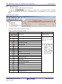
Table 5-1 Project Tree Panel Icons
Icon
Summary
The corresponding peripheral function is already set.
The corresponding peripheral function is not set/used.
Right-clicking the name of a peripheral function brings up a context menu.
Table 5-2 Project Tree Panel Context Menu
Item
[Return to Reset Value]
Description
Resets the settings for a selected peripheral function to their Applilet default.
The range of initial settings may vary by function.
R20UT3420EJ0100 Rev1.00
Mar 31, 2015
Page 39 of 48
AP4, Application Leading Tool, Applilet3 Common Operations
User's Manual
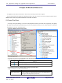
5.2 Module Panel
The Module panel allows you to set peripheral functions. For a description on how to operate the Module panel, see
3.6 Setting up a Peripheral Function.
Figure 5-2 Displaying of Module Panel
Remark: The display positions of the Module panel and Preview panels can be changed by dragging and dropping the
tab.
R20UT3420EJ0100 Rev1.00
Mar 31, 2015
Page 40 of 48
AP4, Application Leading Tool, Applilet3 Common Operations
User's Manual
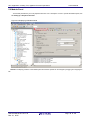
5.2.1 Example of a Module Panel for Clock Generation Circuits
The figure below shows an example of a Module panel for clock generation circuits. By changing functions to be set
through the tabs, you can set an operation, by function. Executing [Return to Reset Value] from the Project Tree panel
resets all tab settings to their default values.
Figure 5-3 Example of a Module Panel (System)
R20UT3420EJ0100 Rev1.00
Mar 31, 2015
Page 41 of 48
AP4, Application Leading Tool, Applilet3 Common Operations
User's Manual
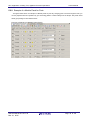
5.2.2 Example of a Module Panel for Ports
The figure below shows an example of a Module panel for ports. By changing ports to be set through the tabs, you
can set peripheral function operations by port. Executing [Return to Reset Value] from the Project Tree panel resets
all tab (port) settings to their default values.
Figure 5-4 Example of a Module Panel (Ports)
R20UT3420EJ0100 Rev1.00
Mar 31, 2015
Page 42 of 48
AP4, Application Leading Tool, Applilet3 Common Operations
User's Manual
5.2.3 Example of a Module Panel for a Peripheral Function (1 Channel)
The figure below shows an example of a Module panel for a peripheral function with only one channel installed. The
operation of the peripheral function can be set by setting the various items that are displayed on the panel. Executing
[Return to Reset Value] from the Project Tree panel resets the settings to their default values.
Figure 5-5 Example of a Module Panel (A/D Converter)
R20UT3420EJ0100 Rev1.00
Mar 31, 2015
Page 43 of 48
AP4, Application Leading Tool, Applilet3 Common Operations
User's Manual
5.2.4 Example of a Module Panel for a Peripheral Function (Multiple Channels)
The figure below shows an example of a Module panel for a peripheral function containing multiple channels. By
changing channels to be set through the tabs, you can set peripheral function operations, by channel. Executing
[Return to Reset Value] from the Project Tree panel resets the settings for the currently selected channel to their
default values.
Figure 5-6 Example of a Module Panel (Compare match timer)
Caution:
Executing the [Return to Reset Value] when a target peripheral function is not displayed on the
Module panel resets the settings for the starting channel (the leftmost tab) to their default values.
R20UT3420EJ0100 Rev1.00
Mar 31, 2015
Page 44 of 48
AP4, Application Leading Tool, Applilet3 Common Operations
User's Manual
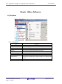
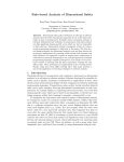
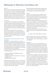
5.2.5 Example of a Module Panel for a Peripheral Function (1 Unit)
The figure below shows an example of a Module panel in which settings change by channel, according to a
selected function. For each channel, select the function to be used, and for each selected channel, set details.
Executing [Return to Reset Value] from the Project Tree panel resets all tab (channel) settings to their default values.
Figure 5-7 Example of a Module panel (Multi Function Timer Puls Unit2)
<1>
<3>
<2>
<4>
Remark: In the example shown in Figure 5-7, settings are specified in the following order:
<1> Select the [general Setting] tab.
<2> Select MTU0 function (the [MTU0] tab is enabled).
<3> Select the [MTU0] tab.
<4> Set details on MTU0.
R20UT3420EJ0100 Rev1.00
Mar 31, 2015
Page 45 of 48
AP4, Application Leading Tool, Applilet3 Common Operations
User's Manual
5.3 Preview Panel
The Preview panel is used to the file and the API function to be output during code generation. For a description of
operating procedure, see 3.7 Checking Source Code.
Figure 5-8 Display of Preview Panel
Preview Tree
Source code display area
(1)Preview Tree
Double-clicking the source file or API function name on the Preview tree changes the display of the source code
display area.
On the Preview tree, the shapes of the icons change according to the status of the settings.
Table 5-3 Preview Tree Icons
Icon
Summary
Peripheral function (unused / used)
File
The API function to be output during code generation (required)
The API function to be output during code generation (user-specifiable)
The API function not to be output during code generation (userspecifiable)
R20UT3420EJ0100 Rev1.00
Mar 31, 2015
Page 46 of 48
AP4, Application Leading Tool, Applilet3 Common Operations
User's Manual
Right-clicking the API function/file name brings up the context menu.
Table 5-4 Preview Tree Context Menu
Item
Object of action
API function (
[Generate Code]
,
)
Description
Sets the API function as an object of output for code
generation.
The icon changes from
[Not Generate Code]
to
.
Excludes the API function from the object of output for
code generation.
The icon changes from
API function (
[Rename]
File (
,
,
)
to
.
) Renames the API function name/file name that is output
during code generation. The name changes to the Edit
mode.
[Default]
Resets to an Applilet3 initial value the API function
name/file name that is output during code generation.
(2)Source code display area
Verifies the source code (a device driver program). Double-clicking the source file name or the API function
name on the Preview Tree switches the source code that is displayed.
The source code in this area is displayed in character colors listed in Table 5-5.
Table 5-5 Source Code Character Colors
Color of
Summary
display
Green
Remarks
Comment statement
Blue
C compiler reserved word
Red
Numeric value
Black
Code
Gray
File name
1.
Source code cannot be edited in this area.
2.
In some API functions (such as API functions for a serial array unit), register value SFRs and
other values are calculated during the code generation process before the function is finalized. For
this reason, the source code displayed in this area may not agree with the source code that is
actually output.
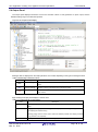
Figure 5-9 Example of an AP Function Display
void INTP_Init( void )
{
EGP0 = INTP_EGP_RESET_VALUE;
EGN0 = INTP_EGN_RESET_VALUE;
EGP1 = INTP_EGP_RESET_VALUE;
EGN1 = INTP_EGN_RESET_VALUE;
INTP_User_Init();
}
R20UT3420EJ0100 Rev1.00
Mar 31, 2015
If this API function (INTP_Init()) is output, the
function is called here.
During code generation, whether this line is to be or
not to be actually output depends on the settings for
the API function (INTP_User_Init()) that is called.
Page 47 of 48
AP4, Application Leading Tool, Applilet3 Common Operations
User's Manual
5.4 Output Panel
The Output panel displays information such as the execution status of code generation or report output, and the
allowable setting range for a selected input field.
Figure 5-10 Output Panel Display
Messages that are displayed on the Output panel are color-coded, depending on the type of message involved.
Table 5-6 Message Character Colors
Color
Type
Normal message
Summary
Indicates information such as the execution status of code generation or report
Black
output.
Blue
Warning message
Displays a warning if the value in the input field is invalid.
Error message
Indicates that the execution of processing is disabled due to a fatal error or
Red
other reasons.
Right-clicking the Output panel displays a context menu.
Table 5-7 Output Panel Context Menu
Item
Clear
Description
Selecting [Clear] from the context menu deletes all messages that are displayed on the Output
panel.
Copy
Dragging a message (character string) on the Output panel selects (producing an inverted
color display) the character string.
Selecting [Copy] from the context menu copies the selected (inverted color display) character
string (stores it in the clipboard).
Select All
Selects (in inverted color display) all the messages (character strings) on the Output panel.
R20UT3420EJ0100 Rev1.00
Mar 31, 2015
Page 48 of 48
AP4, Application Leading Tool, Applilet3 Common Operations
User's Manual
Publication Date:
Rev.1.00
Mar 31, 2015
Published by:
Renesas Electronics Corporation
http://www.renesas.com
SALES OFFICES
Refer to "http://www.renesas.com/" for the latest and detailed information.
Renesas Electronics America Inc.
2801 Scott Boulevard Santa Clara, CA 95050-2549, U.S.A.
Tel: +1-408-588-6000, Fax: +1-408-588-6130
Renesas Electronics Canada Limited
9251 Yonge Street, Suite 8309 Richmond Hill, Ontario Canada L4C 9T3
Tel: +1-905-237-2004
Renesas Electronics Europe Limited
Dukes Meadow, Millboard Road, Bourne End, Buckinghamshire, SL8 5FH, U.K
Tel: +44-1628-585-100, Fax: +44-1628-585-900
Renesas Electronics Europe GmbH
Arcadiastrasse 10, 40472 Düsseldorf, Germany
Tel: +49-211-6503-0, Fax: +49-211-6503-1327
Renesas Electronics (China) Co., Ltd.
Room 1709, Quantum Plaza, No.27 ZhiChunLu Haidian District, Beijing 100191, P.R.China
Tel: +86-10-8235-1155, Fax: +86-10-8235-7679
Renesas Electronics (Shanghai) Co., Ltd.
Unit 301, Tower A, Central Towers, 555 Langao Road, Putuo District, Shanghai, P. R. China 200333
Tel: +86-21-2226-0888, Fax: +86-21-2226-0999
Renesas Electronics Hong Kong Limited
Unit 1601-1611, 16/F., Tower 2, Grand Century Place, 193 Prince Edward Road West, Mongkok, Kowloon, Hong Kong
Tel: +852-2265-6688, Fax: +852 2886-9022
Renesas Electronics Taiwan Co., Ltd.
13F, No. 363, Fu Shing North Road, Taipei 10543, Taiwan
Tel: +886-2-8175-9600, Fax: +886 2-8175-9670
Renesas Electronics Singapore Pte. Ltd.
80 Bendemeer Road, Unit #06-02 Hyflux Innovation Centre, Singapore 339949
Tel: +65-6213-0200, Fax: +65-6213-0300
Renesas Electronics Malaysia Sdn.Bhd.
Unit 1207, Block B, Menara Amcorp, Amcorp Trade Centre, No. 18, Jln Persiaran Barat, 46050 Petaling Jaya, Selangor Darul Ehsan, Malaysia
Tel: +60-3-7955-9390, Fax: +60-3-7955-9510
Renesas Electronics India Pvt. Ltd.
No.777C, 100 Feet Road, HALII Stage, Indiranagar, Bangalore, India
Tel: +91-80-67208700, Fax: +91-80-67208777
Renesas Electronics Korea Co., Ltd.
12F., 234 Teheran-ro, Gangnam-Gu, Seoul, 135-080, Korea
Tel: +82-2-558-3737, Fax: +82-2-558-5141
© 2015 Renesas Electronics Corporation. All rights reserved.
Colophon 4.0
AP4, Application Leading Tool, Applilet3 Common Operations
User’s Manual
R20UT3420EJ0100