1
User’s Manual
2
e studio 4.0
Integrated Development Environment
User’s Manual: Getting Started Guide
Target Device
RX, RL78, RZ Family
www.renesas.com
Rev.3.00 June 2015
Notice
1.
Descriptions of circuits, software and other related information in this document are provided only to illustrate the operation of
semiconductor products and application examples. You are fully responsible for the incorporation of these circuits, software,
and information in the design of your equipment. Renesas Electronics assumes no responsibility for any losses incurred by you
or third parties arising from the use of these circuits, software, or information.
2.
Renesas Electronics has used reasonable care in preparing the information included in this document, but Renesas Electronics
does not warrant that such information is error free. Renesas Electronics assumes no liability whatsoever for any damages
incurred by you resulting from errors in or omissions from the information included herein.
3.
Renesas Electronics does not assume any liability for infringement of patents, copyrights, or other intellectual property rights of
third parties by or arising from the use of Renesas Electronics products or technical information described in this document. No
license, express, implied or otherwise, is granted hereby under any patents, copyrights or other intellectual property rights of
Renesas Electronics or others.
4.
You should not alter, modify, copy, or otherwise misappropriate any Renesas Electronics product, whether in whole or in part.
Renesas Electronics assumes no responsibility for any losses incurred by you or third parties arising from such alteration,
modification, copy or otherwise misappropriation of Renesas Electronics product.
5.
Renesas Electronics products are classified according to the following two quality grades: “Standard” and “High Quality”. The
recommended applications for each Renesas Electronics product depends on the product’s quality grade, as indicated below.
“Standard”:
Computers; office equipment; communications equipment; test and measurement equipment; audio and visual
equipment; home electronic appliances; machine tools; personal electronic equipment; and industrial robots etc.
“High Quality”: Transportation equipment (automobiles, trains, ships, etc.); traffic control systems; anti-disaster systems; anti- crime
systems; and safety equipment etc.
Renesas Electronics products are neither intended nor authorized for use in products or systems that may pose a direct threat to human
life or bodily injury (artificial life support devices or systems, surgical implantations etc.), or may cause serious property damages
(nuclear reactor control systems, military equipment etc.). You must check the quality grade of each Renesas Electronics product
before using it in a particular application. You may not use any Renesas Electronics product for any application for which it is not
intended. Renesas Electronics shall not be in any way liable for any damages or losses incurred by you or third parties arising from
the use of any Renesas Electronics product for which the product is not intended by Renesas Electronics.
6.
You should use the Renesas Electronics products described in this document within the range specified by Renesas Electronics,
especially with respect to the maximum rating, operating supply voltage range, movement power voltage range, heat radiation
characteristics, installation and other product characteristics. Renesas Electronics shall have no liability for malfunctions or
damages arising out of the use of Renesas Electronics products beyond such specified ranges.
7.
Although Renesas Electronics endeavors to improve the quality and reliability of its products, semiconductor products have
specific characteristics such as the occurrence of failure at a certain rate and malfunctions under certain use conditions. Further,
Renesas Electronics products are not subject to radiation resistance design. Please be sure to implement safety measures to guard
them against the possibility of physical injury, and injury or damage caused by fire in the event of the failure of a Renesas
Electronics product, such as safety design for hardware and software including but not limited to redundancy, fire control and
malfunction prevention, appropriate treatment for aging degradation or any other appropriate measures. Because the evaluation of
microcomputer software alone is very difficult, please evaluate the safety of the final products or systems manufactured by you.
8.
Please contact a Renesas Electronics sales office for details as to environmental matters such as the environmental compatibility of
each Renesas Electronics product. Please use Renesas Electronics products in compliance with all applicable laws and regulations
that regulate the inclusion or use of controlled substances, including without limitation, the EU RoHS Directive. Renesas
Electronics assumes no liability for damages or losses occurring as a result of your noncompliance with applicable laws and
regulations.
9.
Renesas Electronics products and technology may not be used for or incorporated into any products or systems whose
manufacture, use, or sale is prohibited under any applicable domestic or foreign laws or regulations. You should not use
Renesas Electronics products or technology described in this document for any purpose relating to military applications or use by
the military, including but not limited to the development of weapons of mass destruction. When exporting the Renesas
Electronics products or technology described in this document, you should comply with the applicable export control laws and
regulations and follow the procedures required by such laws and regulations.
10. It is the responsibility of the buyer or distributor of Renesas Electronics products, who distributes, disposes of, or otherwise
places the product with a third party, to notify such third party in advance of the contents and conditions set forth in this
document, Renesas Electronics assumes no responsibility for any losses incurred by you or third parties as a result of
unauthorized use of Renesas Electronics products.
11. This document may not be reproduced or duplicated in any form, in whole or in part, without prior written consent of Renesas
Electronics.
User’s Man
12. Please contact a Renesas Electronics sales office if you have any questions regarding the information contained in this document or
Renesas Electronics products, or if you have any other inquiries.
(Note 1) “Renesas Electronics” as used in this document means Renesas Electronics Corporation and also includes its majorityowned subsidiaries.
(Note 2)
“Renesas Electronics product(s)” means any product developed or manufactured by or for Renesas Electronics.
(2012.4)
How to Use This Manual
This manual describes the role of the e2 studio integrated development environment for developing applications and
systems and provides an outline of its features.
e2 studio is an integrated development environment (IDE) for RX family, RL78 family and RZ family integrating the
necessary tools for the development phase of software (e.g. design, implementation, and debugging) into a single platform.
By providing an integrated environment, it is possible to perform all development using just this product, without the need to
use many different tools separately.
Readers
This manual is intended for users who wish to understand the functions of the
e2 studio and design software and hardware application systems.
Purpose
This manual aims to provide user with the explanation of the functions provided in e2
studio when they commence the development of their hardware and software systems
using the targeted devices.
Organization
This manual can be broadly divided into the following units.
CHAPTER 1
CHAPTER 2
CHAPTER 3
CHAPTER 4
CHAPTER 5
CHAPTER 6
How to Read This Manual
Conventions
GENERAL
INSTALLATION
PROJECT GENERATION
BUILD
DEBUG
HELP
It is assumed that the readers of this manual have general knowledge of electricity, logic
circuits, and microcontrollers.
Data significance:
Higher digits on the left and lower digits on the right
Active low representation: XXX (overscore over pin or signal name)
Note:
Footnote for item marked with Note in the text
Caution:
Information requiring particular attention
Remark:
Supplementary information
Numeric representation:
Decimal ... XXXX
Hexadecimal ... 0xXXXX
TABLE OF CONTENTS
CHAPTER 1.
1.1.
1.2.
CHAPTER 2.
2.1
2.2.
2.3.
2.4.
2.5.
BUILD ..................................................................................................................... 25
Build Option Settings...............................................................................................................................................25
Build A Sample Project ...........................................................................................................................................27
CHAPTER 4.
5.1.
5.2.
5.3.
PROJECT GENERATION ...................................................................................... 11
New Project Generation ...........................................................................................................................................11
Import Existing Projects Into Workspace ................................................................................................................15
HEW Project Import ................................................................................................................................................21
CS+ Project Import ..................................................................................................................................................23
CHAPTER 3.
4.1.
4.2.
INSTALLATION ...................................................................................................... 4
Installation of e2 studio IDE ......................................................................................................................................4
Un-installation of e2 studio IDE .................................................................................................................................5
Minor Version Update for e2 studio IDE...................................................................................................................6
Major Version Upgrade for e2 studio IDE ...............................................................................................................10
Installation of Compiler Package .............................................................................................................................10
CHAPTER 2.
3.1.
3.2.
3.3.
3.4.
GENERAL ................................................................................................................. 1
System Configuration ................................................................................................................................................1
Operating Environment..............................................................................................................................................1
DEBUG .................................................................................................................... 28
Change existing debug configuration ......................................................................................................................28
Create New Debug Configurations ..........................................................................................................................32
Basic Debugging Features .......................................................................................................................................34
CHAPTER 5.
HELP........................................................................................................................ 49
e2 studio 4.0
Getting Started Guide
CHAPTER 1. GENERAL
Renesas eclipse embedded studio (known as “e2 studio”) is a complete, state of the art development environment
supporting Renesas embedded micro-controllers. It is developed based on a popular open-source Eclipse CDT
(C/C++ Development Tooling) project that covers build (e.g. editor, compiler and linker control) and debug
phase with an extended GDB interface support.
This chapter describes the system configuration and operating environment for e2 studio IDE to develop
applications for the RX family series microcontrollers as example.
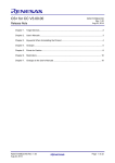
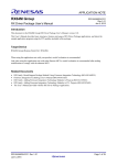
1.1. System Configuration
Below is an example of a typical system configuration.
Host Machine
Emulator
Target Board
Figure 1-1 System Configuration
1.2. Operating Environment
Below are the system requirements for this product.
1.2.1.System Requirements
Hardware Environment:
Processor:
At least 1GHz (support hyper-threading/multi-core CPU)
Main Memory: At least 1GB (2GB or larger is recommended, especially for Windows 64-bit OS)
Display:
Resolution at least 1,024 x 768; at least 65,536 colors
Interface:
USB 2.0 (High-speed/Full-speed). High-speed is recommended.
Software Environment:
Windows 7 (32/64-bit OS), Windows 8 (32/64-bit OS) and Windows 8.1 (32/64-bit OS)
R20UT2771EJ0300
16 June 2015
Page 1 of 50
e2 studio 4.0
1.2.2.
1.2.2.1.
Getting Started Guide
Supported Toolchain
Supported Compiler
Renesas C/C++ compiler package for RX family v2.03
Renesas C compiler package for RL family v1.01
KPIT GNUARM-NONE Windows Tool Chain (ELF)
KPIT GNURX Windows Tool Chain (ELF)
KPIT GNURL78 Windows Tool Chain (ELF)
R20UT2771EJ0300
16 June 2015
Page 2 of 50
e2 studio 4.0
1.2.2.2.
Getting Started Guide
Supported Emulator Device
E1 (RX, RL78, RH850), E20 (RX) and Segger J-Link (RX, RZ)
1.2.2.3.
Supported Simulator Environment
Renesas Simulator (RX), GDB Simulator (RL78)
R20UT2771EJ0300
16 June 2015
Page 3 of 50
e2 studio 4.0
Getting Started Guide
CHAPTER 2. INSTALLATION
The latest e2 studio IDE installer package can be downloaded from Renesas website for free. User has to login to
the Renesas account (in MyRenesas page) for the software download.
This chapter describes the installation, un-installation and online update for the e2 studio IDE.
2.1 Installation of e2 studio IDE
(1) Double-click on e2 studio installer to invoke the e2studio installation wizard page.
Click the [Next] button to continue.
(2) Install Folder
The default installation location is set to: “C:\Renesas\e2_studio”. Input install folder
directly to textbox or click [Browse…] button to modify it.
Select Windows users that e2 studio is installed for.
Click the [Next] button to continue.
(3) Device Families
Select Devices Families to install. Click the [Next] button to continue.
(4) Extra Components
Select Extra Components (i.e. language pack, SVN & Git support, Micrium, RTOS
support) to install. Click the [Next] button to continue.
(5) Components
Select Components and click the [Next] button to continue.
(6) Additional Software
Select additional software (i.e. compilers, utilities) and click the [Next] button to
continue.
(7) License Agreement
Read and accept the software license agreement to proceed with the [Next] button.
Please note that user has to accept the license agreement, otherwise installation cannot
be continued.
(8) Shortcuts
Select shortcut name for start menu and click [Next] button to continue.
(9) Summary
Click the [Install] button to install the Renesas e2 studio IDE.
(10)Installing…
The installation is performed. Based on selected items of Addition Software, new
dialogs are opened to proceed with installation for these software.
(11)Results
Click [Finish] button to complete the installation.
R20UT2771EJ0300
16 June 2015
Page 4 of 50
e2 studio 4.0
Getting Started Guide
2.2. Un-installation of e2 studio IDE
User can uninstall e2 studio program following the typical steps to uninstall a program in Window OS.
(1) Click on [Start] → [Control Panel] → [ Programs and Features]
(2) From the currently installed programs list, choose “e2 studio” and click the [Uninstall] button.
(3) Click the [Uninstall] button to confirm the deletion in the “Uninstall” dialog.
At the end of the un-installation, e2 studio IDE will be deleted from the installed location and Windows
short-cuts menu are removed.
R20UT2771EJ0300
16 June 2015
Page 5 of 50
e2 studio 4.0
Getting Started Guide
2.3. Minor Version Update for e2 studio IDE
e2 studio supports online and offline updates to the minor version update (i.e. number increase in the minor digit,
for example, version up from v4.0.0.21 to v4.0.0.23). This allows the available software components to be
updated through internet or without internet connection.
2.3.1. Online Minor Version Update
This section illustrates an example on the steps to launch the online minor version update
Figure 2-1 [Check for Updates] Menu
(1) From the [Help] menu, click the [Check for Updates] to display the [Available update] panel.
R20UT2771EJ0300
16 June 2015
Page 6 of 50
e2 studio 4.0
Getting Started Guide
Figure 2-2 e2 studio – Available Updates panel (1/3)
(2) By default, all the software components are selected in the [Available Updates] panel. This
allows user to update them all to the latest version. (An example is shown in Figure 2-2)
(3) Click the [Next] button to proceed.
Figure 2-3 e2 studio – Available Updates panel (2/3)
(4) Select the [Next] button to continue the update.
R20UT2771EJ0300
16 June 2015
Page 7 of 50
e2 studio 4.0
Getting Started Guide
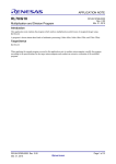
Figure 2-4 e2 studio – Available Updates panel (3/3)
(5) Read and check the software license agreement. Click the [Finish] button to complete update.
Figure 2-5 e2 studio – About e2 studio panel
(6) Click the [Help] → [About e2 studio] to confirm the updated version.
R20UT2771EJ0300
16 June 2015
Page 8 of 50
e2 studio 4.0
Getting Started Guide
2.3.2. Offline Minor Version Update
This section illustrates how to update e² studio without the Internet connections
(1) Download the “Differential Update program” file of e² studio from the following Renesas URL:
http://www.renesas.com/e2studio_download
Note: This procedure cannot be applied to the revisions with no published update files.
(2) Select [Preferences] from the [Window] menu of the e² studio.
Figure 2-6 e2 studio – Available Software Sites
(3) Click the [Available Software Sites] in the [Install/Update] tree list on the "Preferences" dialog.
If any "Available Software Sites" have been checked in this dialog, uncheck all of them.
Figure 2-7 e2 studio – Add Site
(4) Click the [Add…] button and open the "Add Site" dialog. Click on the [Archive] button on the
"Add Site" dialog, and select the update file downloaded in step (1).
R20UT2771EJ0300
16 June 2015
Page 9 of 50
e2 studio 4.0
Getting Started Guide
Figure 2-8 e2 studio – Local Site Is Selected In Available Software Sites
(5) Click the [OK] button to return to the "Preferences" dialog and confirm that the checkbox of the
local site added in step (4) is selected in the "Available Software Sites" list. Click on the [OK]
button.
(6) Select [Check for Updates] in the [Help] menu of e² studio to start update procedure. Further
operations are the same as online updates.
2.4. Major Version Upgrade for e2 studio IDE
Since [Check for Updates] operation is not applicable for major version upgrades (i.e. the number increase in the
major digit, for example, version up from v.3.1.3.06 to v.4.0.0.15), you need e² studio installer for major
upgrades. Please note that you should not do overwrite onto existing installation. Prior to the IDE upgrade,
user must uninstall the old version IDE. However, to keep both old and new IDE versions, user can create new
folder as installation destination for the new version IDE.
2.5. Installation of Compiler Package
V4.0 or newer e² studio installer have the capability to install compiler packages. However, without Internet
connections or by using V3.1 or older installers, compiler packages are not installed together. Compiler
packages (and the instructions for them) are available at the following web sites.
Renesas Compiler Package download sites:
For RX Family: http://www.renesas.com/rx_c_download
For RL78 Family:
http://www.renesas.com/rl78_c
KPIT GNU Toolchain download site:.
http://www.kpitgnutools.com/latestToolchain.php?os=WIN
R20UT2771EJ0300
16 June 2015
Page 10 of 50
e2 studio 4.0
Getting Started Guide
CHAPTER 3. PROJECT GENERATION
This chapter describes the creation of new project and import of existing High-performance Embedded
Workshop IDE (described as “HEW” below) project to e2 studio IDE.
Note: 1. To install and use the e2 studio on your PC, you must install the compiler package provided
separately.
2. Multi-byte characters cannot be used for e2 studio installation folder name, project name and its
folder, and source file name.
3.1. New Project Generation
To create a new project with Renesas RXC toolchain, invoke e2 studio IDE from the Windows ([Start] menu)
and specify a workspace directory.
(1) Click [File] → [New] → [C Project] to create a new C Project. New project creation Wizard as
shown below will start.
Figure 3-1 New Project Creation Wizard (1/4)
(2) Enter the project name and select toolchains: “Renesas RXC Toolchain”. Click [Next] to
continue. If “Renesas RXC Toolchain” is not available, please follow the steps in Section 2.5 to
install ‘RX Compiler Package’.
R20UT2771EJ0300
16 June 2015
Page 11 of 50
e2 studio 4.0
Getting Started Guide
Figure 3-2 New Project Creation Wizard (2/4)
(3) Select Toolchain Version: “v2.03.00”, Debugger Hardware: “E1” and target device: “RX64M
(176 pin device, part number: R5F564MLCxFC). Click [Next] to proceed
R20UT2771EJ0300
16 June 2015
Page 12 of 50
e2 studio 4.0
Getting Started Guide
Figure 3-3 New Project Creation Wizard (3/4)
(4) Check the “Use Peripheral code Generator” option if available (for e.g. if the target device is
"RX111”, “RX64M”), otherwise ignore this setting. Click [Finish] to complete.
Note: Peripheral Code Generator may not be available for some devices
Figure 3-4 New Project Creation Wizard (4/4)
(5) A project summary is displayed. Click [Ok] to generate the project.
R20UT2771EJ0300
16 June 2015
Page 13 of 50
e2 studio 4.0
Getting Started Guide
Figure 3-5 New C Project Created
(6) A brand new C project named “Tutorial” is created.
This project consists of an application file “Tutorial.c” and standard start-up files (e.g. “dbsct.c”,
“interrupt_handlers.c”, “sbrk.c” etc). All these project and source files listed in the [Project Explorer] panel
reflects the folder structure of the project, just as seen on the standard file explorer.
Notes for backing up projecs:
Project properties are stored in files and folders which beginning with '.' (dot). Therefore, whole project folder
should be archived to take backups. For projects referring to other project's files, to restore properties shared
among projects, please backup whole workspace folder.
R20UT2771EJ0300
16 June 2015
Page 14 of 50
e2 studio 4.0
Getting Started Guide
3.2. Import Existing Projects Into Workspace
This section explains how to import existing projects from a directory or an archive into workspaces.
Figure 3-6 Import Existing Projects Wizard
(1) In e2 studio IDE, click [File] → [Import] to open the HEW Project import wizard. Select “Existing
Projects into Workspace” and click [Next] button to open “Import Projects” window.
R20UT2771EJ0300
16 June 2015
Page 15 of 50
e2 studio 4.0
Getting Started Guide
Figure 3-7 Import Projects Window In e2 studio IDE
(2) Browse for a directory or an archive that stores the projects. All existing project are shown.
Select projects to be imported and click [Finish] button to complete importing the projects.
R20UT2771EJ0300
16 June 2015
Page 16 of 50
e2 studio 4.0
Getting Started Guide
Figure 3-8 Projects Import In e2 studio IDE
(3) The project has been successfully imported to the e2 studio IDE.
R20UT2771EJ0300
16 June 2015
Page 17 of 50
e2 studio 4.0
Getting Started Guide
Instead of import project with the existing project name, e2 studio allows the project to be renamed.
With this option, only one project can to be imported at a time.
Figure 3-9 Import And Rename Project Wizard
(1) In e2 studio IDE, click [File] → [Import] to open the HEW Project import wizard. Select
“Rename & Import Existing C/C++ Project into Workspace” and click [Next] button to open
“Rename & Import Project” window.
R20UT2771EJ0300
16 June 2015
Page 18 of 50
e2 studio 4.0
Getting Started Guide
Figure 3-10 Rename & Import Project Window In e2 studio IDE
(2) Browse for a directory or an archive that stores the projects. All existing project are shown.
Select a project, input its new name and click [Finish] button to import this project.
R20UT2771EJ0300
16 June 2015
Page 19 of 50
e2 studio 4.0
Getting Started Guide
Figure 3-11 Project Rename And Import In e2 studio IDE
(3) The project has been successfully renamed and imported to the e2 studio IDE.
R20UT2771EJ0300
16 June 2015
Page 20 of 50
e2 studio 4.0
Getting Started Guide
3.3. HEW Project Import
This section explains HEW import feature to migrate existing project workspace to the e2 studio IDE.
This enables code re-usability for application codes and workspace created in HEW IDE previously.
Figure 3-12 HEW Project Import Wizard
(3) In e2 studio IDE, click [File] → [Import] to open the HEW Project import wizard. Select “HEW
Project” and click [Next] button to open ‘Import HEW Project(s)’ window.
(4) Browse for the HEW Project file (.hwp) and click [Finish] button to import this project.
R20UT2771EJ0300
16 June 2015
Page 21 of 50
e2 studio 4.0
Getting Started Guide
Figure 3-13 Project Migration from HEW to e2 studio IDE
(3) The HEW project has been successfully imported to the e2 studio IDE.
After conversion, all the original project and source files are kept with the newly generated project
workspace in e2 studio IDE. In addition, “.cproject”, “.*linker”, “.info” and “.project” are created and added.
Both the HEW and e2 studio project workspaces share the same files in the physical file location.
If HEW project import fails, please check the following two (2) pre-requisite conditions:
(i) HEW project workspace must be of the version, v4.07 and above
(ii) Files e.g. “.cproject”, “.*linker”, “.info” and “.project” must be deleted manually for HEW project
re-import.
R20UT2771EJ0300
16 June 2015
Page 22 of 50
e2 studio 4.0
Getting Started Guide
3.4. CS+ Project Import
For code re-usability purpose, this section explains the CS+ import feature to migrate existing project workspace
to the e2 studio IDE.
Figure 3-14 CS+ Project Import Wizard (1/2)
In e2 studio IDE, click [File] → [Import]. Select “Renesas Common Project File” and click [Next] button to
proceed. “Import Projects” window will open.
(1) Browse for the CS+ Project file (.rcpe) and click [Finish] button to import this project.
Figure 3-15 Project Migration from CS+ to e2 studio IDE
(2) The CS+ project has been successfully imported to the e2 studio IDE.
R20UT2771EJ0300
16 June 2015
Page 23 of 50
e2 studio 4.0
Getting Started Guide
After conversion, all the original project and source files are kept with the newly generated project
workspace in e2 studio IDE. In addition, “.cproject”, “.*linker”, “.info” and “.project” are created and
added. Both the CS+ and e2 studio project workspaces share the same files in the physical file
location.
R20UT2771EJ0300
16 June 2015
Page 24 of 50
e2 studio 4.0
Getting Started Guide
CHAPTER 4. BUILD
This chapter describes the build configurations and key build features for e2 studio IDE.
4.1. Build Option Settings
The default build option is generated when a project is created and it can usually be used to build the project.
However, if changing build option is necessary (e.g. Toolchain version, Optimization options, etc.), please
follow the following steps before building the project.
Figure 4-1 Properties for Tutorial Project and Properties for Tutorial.c Source File
Build option can be accessed in the properties window of a project or a source file.
(1)
Set the focus at the project “Tutorial” or set the focus at the source file Tutorial.c
(2) Click the icon
(or right-click to select [Properties], or use shortcut keys [Alt]+[Enter] or
[Alt]+[T]) to open properties dialog.
R20UT2771EJ0300
16 June 2015
Page 25 of 50
e2 studio 4.0
Getting Started Guide
(3) Click “C/C++ Build” option to view or edit the configuration settings.
Properties window is supported at workspace, project and source level. Properties window for project
supports more configuration which applies across all the files within the same project workspace.
Figure 4-2 Change Toolchain Version
(1) Click [C/C++ Build] → [Change Toolchain Version] to view or change toolchain version.
Refer to figure 4-2, the current version is v2.03.00 and click the “Available Versions” option to
change toolchain version (if additional toolchain is installed).
Figure 4-3 Build Settings for Compiler: Environment
(2) Click [C/C++ Build] → [Environment] to set build option and add or edit the environment
variables.
Build option allows user to retain all the toolchain configuration settings, including path name specified
by using the environment variables. The current build configuration is “HardwareDebug [Active]”, as
shown in Figure 4-3.
The detail of build option is described in compiler user manual which is stored at “{Compiler installation
directory}\doc”. For example, it can be found in “C:\Program Files\Renesas\RX\2_3_0\doc\ ".
R20UT2771EJ0300
16 June 2015
Page 26 of 50
e2 studio 4.0
Getting Started Guide
4.2. Build A Sample Project
Figure 4-4 Build a Sample “Tutorial” Project
(1) Under e2 studio IDE environment, create a new project named “Tutorial” (or open any existing
project).
(2) In [Project Explorer], click at the project to set focus.
(3) Click [Project] → [Build Project] or
icon to build this project.
The [Console] pane shows ‘Build complete.’ message to indicate a successful build. At the end of this
build, files output to the ${CONFIGDIR} directory consists of “makefile”, “Tutorial.abs”, “Tutorial.map”,
“Tutorial.mot”, “Tutorial.x” etc.
“Tutorial.abs” is a Renesas standard load module in ELF/DWARF format (*.abs) used for the
debugging. Because GDB supports a load module format with different ELF/DWARF specification (*.x),
hence “Tutorial.abs” has to be converted to “Tutorial.x” for the debugging in e2 studio IDE.
R20UT2771EJ0300
16 June 2015
Page 27 of 50
e2 studio 4.0
Getting Started Guide
CHAPTER 5. DEBUG
This chapter describes the usage of debug configuration and key debugging features for e2 studio IDE. The
following illustration refers to “Tutorial” project built (in Chapter 4.2) and based on hardware configuration: E1
emulator and RSK RX64M board.
Figure 5-1 Switch to [Debug] Perspective
(1) Open “Tutorial” project workspace in e2 studio IDE and click [Debug] perspective.
Perspective defines the layout views (related to development tools) in the Workbench window. Each perspective
consists of a combination of views, menus and toolbars that enable user to perform specific task.
For instance, [C/C++] perspective has views that help user to develop C/C++ programs and [Debug] perspective
has views that enable user to debug the program. If user attempts to connect up the debugger in the [C/C++]
perspective, IDE will then prompt users to switch to the [Debug] perspective.
One or more perspectives can exist in a single Workbench window. User can customize them or add new
perspective.
Note: For more information on debug, please refer to “e2 studio Debug Help” as described in chapter 6.
5.1. Change existing debug configuration
The debug configuration has to be configured when debugging for the first time and it just needs to be done
once. An existing debug configuration can be changed as follows.
Figure 5-2 Open Debug Configurations Window
(1) Click “Tutorial” Project in [Project Explorer] pane to set focus.
Click [Run] → [Debug Configurations…] or
icon (downward arrow) → [Debug
Configurations…] to open the “Debug Configurations” window.
R20UT2771EJ0300
16 June 2015
Page 28 of 50
e2 studio 4.0
Getting Started Guide
Figure 5-3 Select Load Module
(2) In “Debug Configurations” windows, expand the “Renesas GDB Hardware Debugging” debug
configuration and click on existed debug configuration (e.g. “Tutorial HardwareDebug”).
(3) Go to the [Main] tab and browse to add the load module “Tutorial.x” located in the project build
folder.
Figure 5-4 Select Target Device
(4) Switch to the [Debugger] tab, set “E1” as the debug hardware and “R5F564ML” as the target
device.
•
Debug Hardware: “E1”
•
Target Device: “R5F564ML”
R20UT2771EJ0300
16 June 2015
Page 29 of 50
e2 studio 4.0
Getting Started Guide
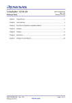
Figure 5-5 Change Connection Setting
(5) Under the [Debugger] tab, go to the [Connection Settings] sub tab to configure the following
based on the settings in E1 emulator and RSK RX64M board:
•
Clock
- Main Clock Source = “EXTAL”
- Extal Frequency(MHz) = “24.0000”
•
Connection with Target Board
- Connection Type = “JTag”
- JTag Clock Frequency [MHz] = “16.5”
•
Power
- Power Target From The Emulator (MAX 200mA) = “No”
•
Communication Mode
- Mode = “Debug Mode”
When “Power Target From The Emulator (MAX 200mA)” is set to “Yes”, the emulator will power up
(with current up to 200mA) the target board without an external power source
Note: This debug configuration in Figure 5-5 is shown as an example. The wrong settings may cause
malfunction or damage to the hardware. So, do be cautious to verify the board and emulator
settings
before connection.
R20UT2771EJ0300
16 June 2015
Page 30 of 50
e2 studio 4.0
Getting Started Guide
In addition, e2 studio also provides the function of duplicating existing project debug configuration for a new
project. This is applicable for the projects using the same device and debugger settings.
Figure 5-6 Change Debug Tool Settings
(6) Switch to [Debug Tool Settings] sub tab, based on the RSK RX64M board to ensure
•
Memory
Endian = “Little Endian”
(7) Click [Apply] button to confirm the settings.
(8) Click [Debug] to execute the debug launch configuration to connect to the E1 and RSK RX64M
board.
R20UT2771EJ0300
16 June 2015
Page 31 of 50
e2 studio 4.0
Getting Started Guide
Figure 5-7 User Target Connection in the [Debug] View
For a successful connection, [Debug] view to show target debugging information in a tree hierarchy. The
program entry point is set at “PowerON_Reset() in “r_cg_resetprg.c”.
5.2. Create New Debug Configurations
The simplest way to create a new debug configuration is by duplicating an existing one. It can be done by the
following steps.
Figure 5-8 Open Debug Configurations Window
(1) Click “Tutorial” Project in [Project Explorer] pane to set focus.
Click [Run] → [Debug Configurations…] or
icon (downward arrow) → [Debug
Configurations…] to open the “Debug Configurations” window.
R20UT2771EJ0300
16 June 2015
Page 32 of 50
e2 studio 4.0
Getting Started Guide
Figure 5-9 Duplicate A Selected Debug Launch Configuration
(2) In “Debug Configurations” window, select a debug configuration (e.g. “Tutorial
HardwareDebug”) and then click
icon (Duplicates the currently selected launch
configuration). A new debug launch configuration (e.g. “Tutorial HardwareDebug (1)”) is
created.
(3) The debug configuration can be configured as described in chapter 5.1.
R20UT2771EJ0300
16 June 2015
Page 33 of 50
e2 studio 4.0
Getting Started Guide
5.3. Basic Debugging Features
This section explains the typical Debug views supported in e2 studio IDE.
• Standard GDB Debug (supported by Eclipse IDE framework): Breakpoints, Expressions,
Registers, Memory, Disassembly and Variables
•
Renesas Extension to Standard GDB Debug: Eventpoints, IO Registers and Trace.
To open “Debug Toolbar”, click the pull down menu button and check on [Show Debug Toolbar]. The
following are some useful toolbars exist in the [Debug] view:
Download
Reset
Restart
Resume (F8)
Disconnect
Suspend
Step Into (F5)
Terminate
(Cltrl+F2)
Step Over (F6)
Check here to show debug
operation icons
Figure 5-11 Useful Toolbars in Debug Views
The program is run by clicking
button or pressing [F8].
The program can be paused by breakpoint or by clicking
perform the following operations:
button. When program is paused, user can
•
button or [F5] can be used for stepping into the next method call at the currently executing line of
code.
•
button or [F6] can be used for stepping over the next method call (executing but without entering
it) at the currently executing line of code.
•
button can be clicked again to resume running.
To stop the debugging process,
button is clicked to end the selected debug session and/or process or
button is clicked to disconnect the debugger from the selected process.
The other operations are as following:
•
button can be clicked to start new debug session.
•
button can be clicked to reset the program to entry point at the PowerOn Reset.
•
button is used for re-downloading the binary file to target system.
R20UT2771EJ0300
16 June 2015
Page 34 of 50
e2 studio 4.0
Getting Started Guide
5.3.1. Breakpoints View
Breakpoints view stores the breakpoints that set on an executable line of a program. If the breakpoint is enabled
during debug, the execution suspends before that line of code executes.
Figure 5-12 [Breakpoint] View
To set a breakpoint,
(1) In “main.c” at line 134, double-click on the marker bar located in the left margin of the [C/C++
Editor] pane to set a software breakpoint. A dot is displayed in the marker bar.
(2) Click [Show View] → [Breakpoint] or icon
(or use shortcut key [ALT]+[Shift]+[Q], [B]) to
open [Breakpoints] view to view the corresponding software breakpoint set. Software
breakpoints can be enabled and disabled in [Breakpoints] view. A disabled breakpoint is
displayed as a white .
To disable breakpoints, user can choose to disable breakpoints selectively or to skip all breakpoints.
(1) To disable a breakpoint selectively, double-click on the
located in the left margin of [C/C++
Editor] pane or uncheck the related line in Breakpoints view. A white dot will appear to indicate
breakpoint has been disabled.
(2) To skip all breakpoints, click on the
icon in the Breakpoints view. A blue dot with a
backslash will appear in the editor pane as well as in the Breakpoints view.
5.3.2. Expressions View
Expressions view monitors the value of global variable, static variable or local variable during debugging. For
all RX debuggers, these variables (including the local variables in scope) can be set for real-time refresh.
Figure 5-13 [Expression] View
R20UT2771EJ0300
16 June 2015
Page 35 of 50
e2 studio 4.0
Getting Started Guide
To watch a global variable,
(1) Click[Show View] → [Expressions] or icon
to open the [Expressions] view
(2) In “main.c” at line 114, drag and drop a global variable (e.g. “gPeriodic_Delay”) over to the
[Expressions] view. (Alternatively, right-click at the global variable to select “Add Watch
Expression…”menu item to add it to the [Expressions] view).
(3) In the [Expressions] view, right-click to select “Real-time Refresh” menu item. This refresh the
expression value in real-time when program is running. The character “R” indicates that this
global variable will be updated in real-time.
(4) To disable the “Real-time Refresh”, simply right-click to select “Disable Real-time Refresh”
menu item.
5.3.3. Registers View
Register view lists the information about the general registers of the target device. Changed values are
highlighted when the program stops.
Figure 5-14 [Registers] View
To view the general register “r0”,
(1) Click [Show View] → [Registers] or icon
to open the [Registers] view.
(2) Click “r0” to view the values in different radix format.
Values that have been changed are highlighted (e.g. in yellow) in the [Registers] view when the program stops.
R20UT2771EJ0300
16 June 2015
Page 36 of 50
e2 studio 4.0
Getting Started Guide
5.3.4. Memory View
Memory view allows users to view and edit the memory presented in “memory monitors”. Each monitor
represents a section of memory specified by its location called “base address”. The memory data in each
memory monitor can be presented in different “memory renderings”, which are the predefined data formats (e.g.
Hex integer, signed integer, unsigned integer, ASCII, image etc).
The global variable “data1” is
presented in memory renderings
of “Hex Integer” format.
Memory Monitor for “Data1”
is specified by the address
“&Data1”
Figure 5-15 [Memory] View (1/2)
To view memory of a variable (e.g. “Data1”),
(1) Click [Show View] → [Memory] or icon
(2) Click the icon
“Data1”.
R20UT2771EJ0300
16 June 2015
to open the [Memory] view.
to open [Monitor Memory] dialog box. Enter the address of the variable
Page 37 of 50
e2 studio 4.0
Getting Started Guide
Figure 5-16 [Memory] View (2/2)
To add new renderings format (e.g. Raw Hex) for the variable “Data1”,
(1) Click the tab
to select “Raw Hex” to add the rendering
This creates a new tab named “&Data1 < Raw Hex>” next to the tab “&Data1<Hex Integer>”.
R20UT2771EJ0300
16 June 2015
Page 38 of 50
e2 studio 4.0
Getting Started Guide
5.3.5. Disassembly View
Disassembly view shows the loaded program as assembler instructions mixed with the source code for the
comparison. Current executing line is highlighted by an arrow marker in the view. In the [Disassembly] view,
user can set breakpoints at the assembler instruction, enable or disable these breakpoints, step through the
disassembly instructions and even jump to a specific instruction in the program.
Opcodes
Function Offsets
This allows the assembly
source to be linked with the
C source (active debug
context).
Figure 5-17 [Disassembly] View
To view both C and assembly codes in a mixed mode,
(1) Click[Show View] → [Disassembly] or icon
to open the [Disassembly] view
(2) Click icon
to enable the synchronization between assembly source and the C source
(active debug context).
(3) In [Disassembly] view, right-click at the address column to select “Show Opcodes” and “Show
Function Offsets”.
(4) You can enable source addresses within the editor using the context menu.
R20UT2771EJ0300
16 June 2015
Page 39 of 50
e2 studio 4.0
Getting Started Guide
Figure 5-18 Source Addresses Menu
Figure 5-19 Source Addresses displayed in Editor
R20UT2771EJ0300
16 June 2015
Page 40 of 50
e2 studio 4.0
Getting Started Guide
5.3.6. Variables View
Variables view displays all the valid local variables in the current program scope.
Figure 5-20 [Variables] View
To observe a local variable (e.g. “compare_match” for function “StartDebounceTimer()”),
(1) Click [Show View] → [Variables] or icon
to open the [Variables] view.
(2) Step into the function “StartDebounceTimer ()” to view the value of local variable
“compare_match”.
R20UT2771EJ0300
16 June 2015
Page 41 of 50
e2 studio 4.0
Getting Started Guide
5.3.7. Eventpoints View
An event refers to a combination of conditions set for executing break or trace features during program
execution. [Eventpoints] view enables user to set up or view defined events of different category e.g. trace start,
trace stop, trace record, event break, before PC, performance (timer) start and performance (timer) stop.
The number of events that can be set and the setting conditions differ with each MCU. These are two (2) types
of events:
•
Execution address: The emulator detects execution of the instruction at the specified address
by the CPU. It can be a “before PC” break (e.g. with event condition is satisfied immediately
before execution of the instruction at the specified address) or other events (e.g. with event
condition is satisfied immediately after execution of the instruction at the specified address).
•
Data access: The emulator detects access under a specified condition to specified address or
specified address range. This allows to setup complex address and data matching criteria.
Event combination (e.g. OR, AND (cumulative) and Sequential) can be applied to two (2) or more events.
Figure 5-21 [Eventpoints] View (1/2)
To set an event break for a global variable when address/data is matched (e.g. when gFlashCount = “0xB0”),
(1) Click [Show View] → [Eventpoints] or icon
to open the [Eventpoints] view.
(2) Double-click at “Event Break” option to open [Edit Event Break] dialog box
(3) Click [Add…] button to continue.
R20UT2771EJ0300
16 June 2015
Page 42 of 50
e2 studio 4.0
Getting Started Guide
Figure 5-22 [Eventpoints] View (2/2)
(4) Select “Data Access” as the eventpoint type.
(5) Go to the [Address Settings] tab, click the icon
to browse for the symbol “_$gFlashCount”.
(The address of this global variable is “&_$gFlashCount”)
(6) Next, switch to the [Data Access Settings] tab, enable the [Compare Settings] checkbox and
set the compare value equals to “0xB0”. Click [Ok] to proceed.
(7) Ensure that the event break for “gFlashCount = 0xB0” is set and enabled in the [Eventpoints]
view. Reset to execute the program from the start.
R20UT2771EJ0300
16 June 2015
Page 43 of 50
e2 studio 4.0
Getting Started Guide
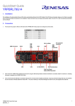
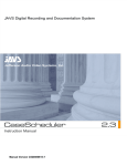
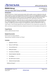
Figure 5-23 Execution of Event Break
Figure 5-23 shows that when gFlashCount reaches the value of 176 (or 0xB0), the program stops at code line no.
76.
R20UT2771EJ0300
16 June 2015
Page 44 of 50
e2 studio 4.0
Getting Started Guide
5.3.8. IO Registers View
IO Registers is also known as the Special Function Registers (SFR). The [IO Register] view displays all the
registers set defined in a target-specific IO file. User can further customize own [IO registers] view by adding
IO registers selectively to the [Selected Registers] pane.
Figure 5-24 [IO Registers] View
To view selected IO registers (e.g. PDR and PCR in PORT0),
(1) Click [Windows] → [Show View] → [Others…]. In “Show View” dialog, click [IO Registers]
under [Debug] or icon
to open the [IO Registers] view
(2) Under the [All Registers] tab, locate [PORT0] in the [IO Registers] view. Expand the PORT0 IO
register list.
(3) Drag and drop the “PDR” and “PCR” to the [Selected Registers] pane. A green dot
the IO register indicates the status of being the selected register(s).
besides
(4) Switch to the [Selected Registers] tab to view “PDR” and “PCR” of the “PORT0” IO register
The expanded IO register list may take a longer time to load in the [All Registers] pane. Hence, it is advisable to
customize and view multiple selected IO registers from the [Selected Registers] pane.
R20UT2771EJ0300
16 June 2015
Page 45 of 50
e2 studio 4.0
Getting Started Guide
5.3.9. Trace View
Tracing means the acquisition of bus information per cycle from the trace memory during user program
execution. The acquired trace information is displayed in the [Trace] view. It helps user to track the program
execution flow to search for and examine the points where problems arise.
The trace buffer is limited (with size of 1 to 32 Mbytes), oldest trace data is overwritten with the new data after
the buffer has become full.
Figure 5-25 [Trace] View (1/2)
To set a point-to-point trace between the two (2) functions (e.g. tracing from function “main()” to “sort()”),
(1) Click [Windows] → [Show View] → [Others…]. In “Show View” dialog, click [Trace] under
[Debug] or icon
to open the [Trace] view.
(2) Turn on the Trace view by selecting the
(3) Click icon
icon.
(Acquisition) to set
•
Trace Mode: "Fill until stop”
•
Trace Type: “Branch”
(1) Click [OK] to proceed.
R20UT2771EJ0300
16 June 2015
Page 46 of 50
e2 studio 4.0
Getting Started Guide
Figure 5-26 [Trace] View (2/2)
(2) Click
(Edit Trace Event Points) to open [Trace Eventpoints] dialog box
(3) Under the [Start] tab, add the 1st event point at “main()” function (by the execution address
“&main”, or 0xFFFC8228).
(4) Then, switch to [Stop] tab, add the 2nd event point at “Display_LCD()” function (by the
execution address “&Display_LCD”, or 0xFFFC816F).
(5) Next, execute the program after reset.
R20UT2771EJ0300
16 June 2015
Page 47 of 50
e2 studio 4.0
Getting Started Guide
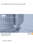
Disassembly
Filter
Save
Source
Reverse
Order
Trace
On/Off
Bus
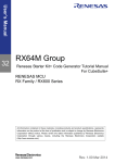
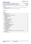
Figure 5-27 Point-to-Point Trace between Two Functions
Figure 24 shows the trace result from function “main()” to “Display_LCD ()”. The trace result can be filtered by
the key trace parameters (e.g. branch type, address range) and saved to a .xml format (with the inclusion of bus,
assembly and source information).
R20UT2771EJ0300
16 June 2015
Page 48 of 50
e2 studio 4.0
Getting Started Guide
CHAPTER 6. HELP
The help system allows user to browse, search, bookmark and print help documentation from a separate Help
window or Help view within the workbench. User can also access online forum dedicated to e2 studio from here.
Click on [Help] tap to pull down Help menu.
1
2
3
4
Figure 6-1 Help Menu
Quick Help Tips
1 Click [Welcome] for Overview of e2 studio, link to access IDE tutorial and sample, and to view Release
Notes.
2
Click [Help Contents] to open a separate Help window with search function.
3
Click [Dynamic Help] to open Help view within the workbench.
4 Click [RenesasRulz Community Forum] to go online forum that is dedicated to topics and discussion related
to e2 studio IDE. Internet connection is required.
R20UT2771EJ0300
16 June 2015
Page 49 of 50
e2 studio 4.0
Getting Started Guide
Under the [Help Contents] window, there are many useful topics. One of them is the “e2 studio Debug Help”
topic, which provides useful information such as debug configuration, supported number of breakpoints, usage
of emulator etc. It can be launched by clicking on [Help] menu → [Help Contents] → “e2 studio Debug Help”.
R20UT2771EJ0300
16 June 2015
Page 50 of 50
Revision Record
Date
Rev.
Description
Page
Summary
1.00
Sep 30, 2013
-
First Edition issued
2.00
Apr 15, 2014
-
Supporting e2 studio IDE v3.0.0.22
2.10
Dec 08, 2014
-
Supporting e2 studio IDE v3.1.2.09
3.00
June 16, 2015
-
Supporting e2 studio IDE v4.0
e2 studio User’s Manual: Getting Started Guide
Publication Date:
Rev.3.00
June 16, 2015
Published by:
Renesas Electronics Corporation
SALES OFFICES
http://www.renesas.com
Refer to "http://www.renesas.com/" for the latest and detailed information.
Renesas Electronics America Inc.
2801 Scott Boulevard Santa Clara, CA 95050-2549, U.S.A.
Tel: +1-408-588-6000, Fax: +1-408-588-6130
Renesas Electronics Canada Limited
9251 Yonge Street, Suite 8309 Richmond Hill, Ontario Canada L4C 9T3
Tel: +1-905-237-2004
Renesas Electronics Europe Limited
Dukes Meadow, Millboard Road, Bourne End, Buckinghamshire, SL8 5FH, U.K
Tel: +44-1628-585-100, Fax: +44-1628-585-900
Renesas Electronics Europe GmbH
Arcadiastrasse 10, 40472 Düsseldorf, Germany
Tel: +49-211-6503-0, Fax: +49-211-6503-1327
Renesas Electronics (China) Co., Ltd.
Room 1709, Quantum Plaza, No.27 ZhiChunLu Haidian District, Beijing 100191, P.R.China
Tel: +86-10-8235-1155, Fax: +86-10-8235-7679
Renesas Electronics (Shanghai) Co., Ltd.
Unit 301, Tower A, Central Towers, 555 Langao Road, Putuo District, Shanghai, P.R. China 200333
Tel: +86-21-2226-0888, Fax: +86-21-2226-0999
Renesas Electronics Hong Kong Limited
Unit 1601-1611, 16/F., Tower 2, Grand Century Place, 193 Prince Edward Road West, Mongkok, Kowloon, Hong Kong
Tel: +852-2265-6688, Fax: +852 2886-9022
Renesas Electronics Taiwan Co., Ltd.
13F, No. 363, Fu Shing North Road, Taipei 10543, Taiwan
Tel: +886-2-8175-9600, Fax: +886 2-8175-9670
Renesas Electronics Singapore Pte. Ltd.
80 Bendemeer Road, Unit #06-02 Hyflux Innovation Centre, Singapore 339949
Tel: +65-6213-0200, Fax: +65-6213-0300
Renesas Electronics Malaysia Sdn.Bhd.
Unit 1207, Block B, Menara Amcorp, Amcorp Trade Centre, No. 18, Jln Persiaran Barat, 46050 Petaling Jaya, Selangor Darul Ehsan, Malaysia
Tel: +60-3-7955-9390, Fax: +60-3-7955-9510
Renesas Electronics India Pvt. Ltd.
No.777C, 100 Feet Road, HALII Stage, Indiranagar, Bangalore, India Tel: +91-80-67208700, Fax: +91-80-67208777
Renesas Electronics Korea Co., Ltd.
12F., 234 Teheran-ro, Gangnam-Gu, Seoul, 135-080, Korea
Tel: +82-2-558-3737, Fax: +82-2-558-5141
© 2015 Renesas Electronics Corporation. All rights reserved
Colophon 4.0
e2 studio
R20UT2771EJ0300