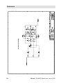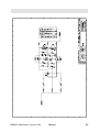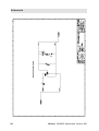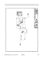
1
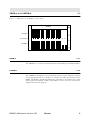
BRUKER
BSMS/2
BSMS/2 Mainframe
Technical Manual
Version 001
Bruker
The information in this manual may be altered without notice.
BRUKER accepts no responsibility for actions taken as a result of use of this manual. BRUKER accepts no liability for any mistakes contained in the manual, leading to coincidental damage, whether during installation or operation of the
instrument. Unauthorised reproduction of manual contents, without written permission from the publishers, or translation into another language, either in full or in
part, is forbidden.
This manual was written by
Robert Schmid
© December 1999: Bruker AG
CH-8117 Faellanden
P/N: Z31476
DWG-Nr: 1179 001
Chapter
Contents
1
1.1
1.2
1.3
2
2.1
2.2
2.3
2.4
3
3.1
3.2
3.3
3.4
3.5
3.6
4
4.1
4.2
4.3
4.4
4.5
5
5.1
5.2
5.3
5.4
5.5
6
6.1
6.2
6.3
7
7.1
7.2
8
8.1
General Description .............................................................. 5
Introduction .................................................................................. 5
Caution ......................................................................................... 5
Troubleshooting ............................................................................ 5
BSMS/2 Chassis and Buses ................................................... 7
Introduction .................................................................................. 7
Installation .................................................................................... 8
VMEBus and USERBus ................................................................ 9
Technical Data ............................................................................ 10
Power Supply Modules ....................................................... 11
Introduction ................................................................................
Installation ..................................................................................
Troubleshooting ..........................................................................
Replacement of a Power Supply Board ........................................
Fuses ..........................................................................................
Technical Data ............................................................................
11
14
16
17
19
21
Central Processing Board CPU .......................................... 23
Introduction ................................................................................
Installation ..................................................................................
CPU Controller Section ..............................................................
CPU Peripheral Section ..............................................................
Technical Data ............................................................................
23
25
25
25
27
BSMS Keyboard KBC ........................................................ 29
Introduction ................................................................................
Installation ..................................................................................
Keyboard Controller Board .........................................................
Keyboard Display Board .............................................................
Technical Data ............................................................................
29
33
33
33
34
Buses and Wiring ................................................................ 35
Line Modul (DC-Fan) ................................................................. 35
Chassis wiring ............................................................................ 36
User Bus wiring .......................................................................... 37
BVT ..................................................................................... 43
BVT and BVT-Supply ................................................................ 43
Assembling Instructions .............................................................. 43
Schemata ............................................................................. 47
Power supply PSB1 place plan .................................................... 47
BSMS/2 Mainframe Version 001
Bruker
3
8.2
8.3
4
Power Supply PSB2 place plan ................................................... 48
Variant Scheme PSB1 / PSB2 ...................................................... 49
Bruker BSMS/2 Mainframe Version 001
Chapter
General Description
1
Introduction
1.1
This manual describes the basic system of the BSMS/2 (Bruker Smart Magnet control System). The mainframe is a modular system providing slots for functional
boards to be plugged in.
The BSMS consists of the following hardware:
1.
One chassis with VME- and User-Bus and line module.
2.
Two power supply modules.
3.
One CPU.
4.
One BSMS keyboard (optional).
5.
Optional BSMS/2 function boards (e.g., SCB, SLCB,…).
The chassis and buses, power supply modules, CPU, and keyboard are discussed in
this manual. The optional BSMS/2 function boards are discussed in additional manuals (e.g., Shim Manual, Sample and Level Manual,…).
Caution
1.2
When turning on the mains switch, the load can cause an excessive start-up current,
which saturates the transformer. The primary current will then exceed the fuse value. To prevent this from happening, a negative temperature coefficient resistor
(NTC) is introduced in the primary path. The NTC limits the primary current in the
start-up phase, but once the unit is in the normal “on” condition, the NTC is warmed
up and does not limit the current.
N.B.: Turning the mains switch off and on repeatedly will blow the mains fuse.
Troubleshooting
1.3
All voltages can be checked via the corresponding LED’s on the front of the boards,
visible from the front of the BSMS/2 chassis (see Corresponding operation indictor
LED’s on page 20). Note, however, that the LED’s only indicate whether power is
present or not. For troubleshooting the power supply modules please see Troubleshooting on page 16.
An error on the CPU or BSMS keyboard is indicated by an error message on the
BSMS keyboard and by the error LED on the CPU. The error message has the format: E: “Error number” CPU_ or KBC_ “Error Text” press ‘STD BY’. For example,
E:1 KBC_ RS timeout. press ‘STD BY’.
BSMS/2 Mainframe Version 001
Bruker
5
General Description
The following steps may be helpful in troubleshooting such an error:
6
1.
Refer to the installation guide and verify that the installation was done correctly.
2.
Check the power supplies to verify that all the power LED’s (green) are lit. The
ready LED on the CPU should either be lit or blinking. The ready LED’s on the
BSMS/2 function boards should be lit. If this is not the case check the power
supply modules (see Troubleshooting on page 16).
3.
Start the BSMS/2 Service Tool ([bsms] in UNIX).
4.
In the service tool submenus [6] ‘board functions CPU…’ and [C] ‘board
functions Keyboard…’ there are functions for debugging the CPU and keyboard,
respectively.
Bruker BSMS/2 Mainframe Version 001
Chapter
BSMS/2 Chassis and Buses 2
Introduction
2.1
The BSMS/2 (Bruker Smart Magnet control System / 2) chassis consists of two 19"racks called front - and back rack. These are shown in Figure 1. The front rack has
16 slots (shown in Figure 2) for boards the size of extended Eurocards. These
boards are plugged on to the backplane, which contains two bus systems: a standard
VMEBus and a deddicated USERBus (shown in Figure 3). The front rack can house
14 boards with VME-Bus interfaces and 2 boards with USER-Bus connections only.
The back rack houses the power supplies and the pneumatic module.
Above the front rack there is the line module which contains:
1.
The mains switch with line filter and fuses.
2.
Five fans to actively cool the BSMS/2.
Figure 1: Front and Back Racks in the BSMS/2
Line Module
Front Rack
BSMS/2 Mainframe Version 001
Back Rack
Bruker
7
BSMS/2 Chassis and Buses
Figure 2: Slots in the BSMS/2 (Front View)
1
2
3
4
CPU 2H-TX SLCB
5
6
GAB
7
8
SCB13L
9
10
11
12
SCB13M
SCB13R
SCB7M
SCB13R
Installation
13
LCB
14 15
16
L-TX ... L-RX ...
2.2
There are no special requirements for installation.
8
Bruker BSMS/2 Mainframe Version 001
VMEBus and USERBus
2.3
Figure 3: Backplane of the BSMS/2 (Front View)
BSMS/2
VMEBus
Slot number
1 2 3 4 5
6 7
8 9
10 11
12 13 14 15 16
USERBus
VMEBus
2.3.1
The VMEBus is a 14 slot A16/A24 D16 board corresponding to the VME standard.
USERBus
2.3.2
The USERBus is designed to route all function specific signals and power supplies
to the appropriate boards or modules. It contains the frame ground point of the
BSMS. The DGND, AGND and GND24 are connected via an inductor (L1) to the
frame ground (for DGND, AGND, and GND24, see also Overview of the Power
Supplies (Part One) on page 12).
BSMS/2 Mainframe Version 001
Bruker
9
BSMS/2 Chassis and Buses
Technical Data
2.4
Table 1. Technical Data of the BSMS/2 Chassis
BSMS/2 Chassis
General
Height
310
mm
Width
485
mm
Depth
482
mm
Weight
32
kg
Front
Rack
Board height
233.35
mm
Board length
220
mm
Back
Rack
Board height
277.8
mm
Board length
160
mm
Dimensions for the chassis.
For chassis equipped with 1×CPU,
1×SLCB, 2×SCB, 1×LCB, 1×L-TX,
1×L-RX, PSB1, PSB2 and 1×PNK module.
Table 2. Technical Data of the Line Module
Line Module
Mains Fuse
5
A
time lag
Mains - Selector
210-230
220-245
195-215
10
Bruker BSMS/2 Mainframe Version 001
Chapter
Power Supply Modules
3
Introduction
3.1
The power requirements of the BSMS/2 are met by two modules PSB1 and PSB2 in
the back rack.The transformer is fixed on the left wall of the rack. Wiring has been
reduced to a minimum.
The mains power is switched by the mains switch, located in the line modul. With
the mains selector it is possible to set primary inputs of transformator on 195215 VAC, 210-230 VAC, or 220-245 VAC. (see Primary Voltage Selection Switch on
page 14).
PSB1 and PSB2 are supplied directly from the secondary side of the transformator
which generates 20 galvanically isulated voltages. PSB1 and PSB2 provide their DC
outputs via J18 and J19 directly to the backplane.
Grounding:
The power supply is constructed so that the different BSMS/2 function elements
(SCB, SLCB, LCB,…) have individual, electrically separate power sources. These
have to be connected at designated positions (see Overview of the Power Supplies
(Part One) on page 12), thus allowing the different grounds to be joined together.
Figure 4: Power Supply Modules in the BSMS/2 (Back View)
Mains Input
Fuses 2 x 5AT
Transformator
PSB2
PSB1
BSMS/2 Mainframe Version 001
Bruker
11
Power Supply Modules
VDD12
VSS12
VCC
DGND
Part One
VDD
AGND
VSS
VDD28
GND28
VCC
DGND
X10V
X5V
XGND
X10VGND
H0_P
H0_GND
H0_N
LOCK_P5V
LOCK_DGND
LOCK_N5V
LOCK_P15V
LOCK_AGND
LOCK_N15V
Figure 5: Overview of the Power Supplies (Part One)
LOCK_P5V
LOCK_DGND
LOCK_N5V
LOCK_P15V
LOCK_AGND
LOCK_N15V
VCC
DGND
VCC
DGND
X5V
XGND
LOCK_P5V
LOCK_DGND
LOCK_N5V
LOCK_P15V
LOCK_AGND
LOCK_N15V
VCC
DGND
H0_P
H0_GND
H0_N
X5V
XGND
Lock Receiver
L_RX...
Lock
Transmitter
L_TX...
LCB
Interface
GND28
AGND
DGND
22uH
PSB2
VDD28
H0_P
H0_N
LOCK_P5V
LOCK_N5V
X5V/X10V
LOCK_P15V
LOCK_N15V
VPWR_P1
VPWR_N1
Frame Ground
SCB13-R
VPWR_P1
VPWR_GND1
VPWR_N1
VDD
AGND
VSS
VCC
DGND
X5V
XGND
VME supply
12
Interface
USER-Bus supply
Bruker BSMS/2 Mainframe Version 001
Figure 6: Overview of the Power Supplies (Part Two)
VME supply
USER-Bus supply
Part Two
SCB7/13-M
VDD
AGND
VSS
VCC
DGND
X5V
XGND
Interface
Interface
PSB1
VCC
VDD12
VSS12
HE_P
PNEU_24V
VDD
VSS
VPWR_P2
VPWR_N2
GAB
X5V
XGND
VCC
DGND
VPWR_P2
VPWR_GND2
VPWR_N2
PSB_VTCB VDD12
VSS12
VDD
AGND
VSS
VCC
DGND
HE_P
HE_GND
PNEU_24V
PNEU_GND
X5V
XGND
VDD
AGND
Inhibit
for
AC/DC
Supply
BVT i.e.
SCB13-L
VPWR_P2
VPWR_GND2
VPWR_N2
HEAT_P
HEAT_GND
VCC
DGND
Interface
+15V
DC
DC
-15V
SLCB
Helium
Circuit
Helium
Sensor
Interface
HEAT_P
HEAT_GND
VCC
DGND
X5V
XGND
VCC
DGND
X5V
XGND
2H-TX
or
RCB
PNEU_24V
PNEU_GND
VDD28
GND28
VDD28
GND28
VDD
AGND
VSS
Pneumatic
Module
PNK..
VCC
DGND
VDD24
GND24
CPU
VCC
DGND
VDD
AGND
VSS
PNEU_24V
BSMS
PNEU_GND
BSMS/2 Mainframe Version 001
Bruker
VPWR_P2
VPWR_GND2
PNEU_24V
PNEU_GND
HE_P
HE_GND
VPWR_N2
VDD
AGND
VSS
VDD28
GND28
VCC
DGND
X10V
X5V
XGND
X10VGND
VDD12
VSS12
VCC
DGND
VDD12
VSS12
X10V
X5V
XGND
Keyboard
Interface
Router
Display
Interface
Computer
13
Power Supply Modules
Installation
3.2
To install the power supply modules please follow the guide below, making sure to do
each step in the order given.
Make sure that the mains cable is disconnected !
1.
Check that the primary voltage selection switch is in the optimal position (see
the sticker on the back side of the power supply module):
To avoid excessive power dissipation in the power modules, the
primary voltage can be adapted by the primary voltage selection
switch (shown in Figure 7). Use a coin or a screwdriver to access
the switch. Generally, the primary voltage selection switch should
be set to the matching range; however, if the mains power is weak,
the next lower range should be chosen despite the greater power
dissipation in the power supply modules.
For Example:
230 V stable mains power ⇒ 220-245VAC position.
230 V unstable mains power ⇒ 210-230VAC position.
Figure 7: Primary Voltage Selection Switch
MAINS SLECTOR
210-230VAC
195-215VAC
220-245VAC
Back Side of the BSMS/2
14
Bruker BSMS/2 Mainframe Version 001
Figure 8: PSB replacement
2.
Insert the power supply modules into the rack from the rear (PSB1 right, PSB2
left) and connect them with the AC-plugs.
3.
Re-mount the cover plate.
4.
Insert the BSMS/2 CPU into SLOT 1 (far left of front rack). Connect the BSMS
keyboard to the CPU.
5.
Plug in the mains cable and turn on the BSMS/2.
6.
All voltage LED’s on the power supply modules and on the CPU should now be
lit and the BSMS keyboard should run (the display should read ‘Stand By’).
7.
In case of a problem, switch off the power supply and check the fuses (see also
Troubleshooting on page 16).
BSMS/2 Mainframe Version 001
Bruker
15
Power Supply Modules
Troubleshooting
3.3
1.
First check if one of the PSB LED’s is not lit. If so, look at the two fans above
the power supply modules. If one of them doesn’t run, that could be the cause
for an overheat protection of voltage regulator. In this case the fuse doesn’thave
to be blown.(For fan replacement see Figure 8)
2.
Switch the BSMS/2 of and disconect the mains power cable.
3.
Verify that the primary voltage selection switch on the power supply module is
in the correct position (see Installation on page 14).
4.
Open the cover plate and replace the fuse corresponding to the LED that dosn’t
light. (For further informations see Fues 3.4)
5.
Now connect the mains power cable, turn on the mains switch and see if the
LED lights.
6.
If the same fault occurs again plug out all modules in the front and back rack on
which the defective supply is used (see Figure5 and 6). Replace the fuse (Step 1
to 4). Switch on the mains and if still a LED dosn’t light the defect is locatated
on this PSB. Otherwise plug in the first module and switch on the mains switch.
Check the LED’s and continue with the next module until a module causes the
DC interruption. The defectiv part is located and has to be replaced by the
BRUKER Troubleshooter.
7.
Change a fan.
Figure 9: Fan replacement 1
Disconnect all cables on front side
of the BSMS/2 and pull it out of the
cabinet.
remove Line Module screws
solder out the two wires
16
Bruker BSMS/2 Mainframe Version 001
Figure 10: Fan replacement 2
cut fan rubber fittings
get a fan repair set
fix the rubber fittings
air direction see
fan side
fan with rubber fittings
place the fan wire side to the solderpads
pull rubber fittings till they snap in cut the rubber fittings
Replacement of a Power Supply Board
BSMS/2 Mainframe Version 001
Bruker
solder the wires red => +
black or blue => -
fix the line module screws
3.4
17
Power Supply Modules
Figure 11: Replacement step by step
Loosen the four screws and remove the
cooling air channel.
Pull the BSMS/2 approximately 15cm (6 inch)
out of the cabinet.
Remove all eight screws of the BSMS/2 rack.
Make shure that the mains switch is turned off and
the mains cable is pluged out !
Then remove the back pannel.
Disconnect the two AC-connectors.
Exchange the defective power supply module.
18
Bruker BSMS/2 Mainframe Version 001
Fuses
3.5
Open the backpanel of the BSMS/2. The fuses are located on each PSB behind the
corresponding LED’s. To exchange a fuse, it is not necessary to plug out the PSB.
The DC-supply names are printed on the backpanel. For ratings of the fuses refer to
Figure 11.
Figure 12: Fuse replacement
PSB2
2258
VCC
6,3AT
1,25AT 2252
VDD12
3,15AT 2256
1,25AT 2252
VSS12
3,15AT 2256
HE_P
0,63AT 2249
2255
VDD28
2,5AT
H0_P
0,63AT 2249
H0_N
0,63AT 2249
LOCK_P5V
LOCK_N5V
X10V/X5V
PSB1
3,15AT 2256
PNEU_24V 1,25AT 2252
LOCK_P15V 1,25AT 2252
VDD
1,25AT 2252
LOCK_N15V 1,25AT 2252
VSS
1,25AT 2252
VPWR_P1
4,0AT
2257
VPWR_P2
8,0AT
2259
VPWR_N1
4,0AT
2257
VPWR_N2
8,0AT
2259
BSMS/2 Mainframe Version 001
Bruker
19
Power Supply Modules
Table 3. Corresponding operation indictor LED’s
Power Supply
Board
20
PSB Voltage (LED)
Operation Indicator (LED)
PSB1
HE_P
SLCB (HE_30V)
PSB1
VDD
CPU (+/-15V)
PSB1
VSS
CPU (+/-15V)
PSB2
X10V & X5V
CPU (X5V)
PSB1
PNEU_24V
SLCB (PNEU_24V)
PSB2
VDD28
CPU (VDD24)
PSB1
VDD12
CPU (+/-12V)
PSB2
VSS12
CPU (+/-12V)
PSB2
H0_P
LCB (+15V, +5V)
PSB2
H0_N
LCB (–15V)
PSB2
LOCK_P15V
L-RX (+/– 15V, L-PWR),
L-TX (L-PWR)
PSB2
LOCK_N15V
L-RX (+/– 15V, L-PWR)
PSB2
LOCK_P5V
L-TX (+/– 5V)
PSB2
LOCK_N5V
L-TX (+/– 5V, L-PWR)
PSB1
VCC
READY and ERROR LED’s on all
boards. If none are lit, VCC is defective.
PSB2
VPWR_N1
SCB R in SLOT 12 (VPWR_VSS)
PSB2
VPWR_P1
SCB R in SLOT 12 (VPWR_VDD)
PSB1
VPWR_P2
GAB, SCB L, M in SLOT 6, 8, 10
(VPWR_VDD)
PSB1
VPWR_N2
GAB, SCB L, M in SLOT 6, 8, 10
(VPWR_VSS)
Bruker BSMS/2 Mainframe Version 001
Technical Data
3.6
Regulated and non-regulated voltages are shown in Table 4 and Table 5, respectively. The following notes are applicable to both tables.
1.
Voltages were measured with a true RMS DVM. The voltage ripple was determined with an oscilloscope and so gives an approximate value.
2.
The rated load was simulated by a resistor.
Table 4. Regulated Voltages
Voltage
Name
Reference
point
Voltage at
rated load
Current at
rated load
Voltage
ripple
VCC
DGND
5 +/– 0.1 V
5.0 A
20 mV
VDD12
DGND
12 +/– 0.7 V
2.5 A
30 mV
VSS12
DGND
–12 +/– 0.7 V
2.5 A
30 mV
H0_P
H0_GND
29.5 +/– 1.8 V
0.5 A
20 mV
H0_N
H0_GND
–29.5 +/– 1.8 V
0.5 A
20 mV
LOCK_P15V
LOCK_AGND
15 +/– 0.6 V
1.0 A
20 mV
LOCK_N15V
LOCK_AGND
–15 +/– 0.6 V
1.0 A
20 mV
LOCK_P5V
LOCK_DGND
5 +/– 0.25 V
1.0 A
20 mV
LOCK_N5V
LOCK_DGND
–5 +/– 0.25 V
1.0 A
20 mV
VDD
AGND
15 +/– 0.6 V
1.0 A
20 mV
VSS
AGND
–15 +/– 0.6 V
1.0 A
20 mV
VDD28
VDD28
27.8 +/- 1.1V
2.0 A
20mV
X5V
XGND
5 +/– 0.3 V
1.0 A
20 mV
BSMS/2 Mainframe Version 001
Bruker
21
Power Supply Modules
Table 5. Non-Regulated Voltages
(Mains voltage: 230 VAC, Primary Voltage Selection Switch Position: 220-245 )
Voltage
Name
22
Reference point
Voltage at
rated load
Current at
rated load
Voltage ripple
(mV)
VPWR_P1
VPWR_GND1
20 - 24 V
3.5 A
800
VPWR_N1
VPWR_GND1
20 - 24 V
3.5 A
800
VPWR_P2
VPWR_GND2
20 - 25 V
6.0 A
1000
VPWR-N2
VPWR_GND2
20 - 25 V
6.0 A
1000
HE_P
HE_GND
35 - 42 V
0.4 A
1000
PNEU_24V
PNEU_GND
21 - 27 V
1.0 A
1500
X10V
X10VGND
8.5 - 11.5 V
1.5 A
800
Bruker BSMS/2 Mainframe Version 001
Chapter
Central Processing Board
CPU
4
Introduction
4.1
The CPU/3 is a BSMS/2 subsystem. It plays a central role in the overall operation of
the BSMS/2. First, it relates all messages from the computer or BSMS keyboard to
the corresponding board (i.e., it serves as the master of the VMEbus). Second, it manages all functions in which more than one board are involved (i. e., autoshim,…).
The CPU is always located in the left-most slot 1 of the BSMS front rack as shown
in Figure 13.
Figure 13: BSMS/2 CPU/3
CPU3
Computer
Keyboard
Router
BSMS/2 Mainframe Version 001
Bruker
23
Central Processing Board CPU
Figure 14: CPU Block Diagram
Controller Section
VMEbus
VMEbus
Interface
Core MC68000
Memory
Parallel Interface
Serial Interface
KEYB
COMP
Transformer
Thermo Switch
RS - 232
I2C
COMP
(galvanically
isolated)
RS - 485
Fan (On/Off)
KEYB
(galvanically
isolated)
USERBus
Relay (On/Off)
Router
Display
Lines
ROUTER
READY
ERROR
VDD24
+/-15V
Supply Voltages
+/-12V
X5V
SYSRESET
24
SYSRESET
Logic
RESET
Bruker BSMS/2 Mainframe Version 001
Installation
4.2
To install the CPU please follow the guide below, making sure to do each step in the order given. No hardware adjustments are necessary for the CPU! However, PLEASE
NOTE that if you exchange the CPU, stored parameters for all boards will be lost. Thus,
adjustments and configurations for all boards will need to be redone. So if you replace a
board do it by the helpful SERVICE features of the BSMS Tool 2.0 and later. Doing
this, the whole configuration will be saved on the computer and then reloaded to the
new CPU (see BSMS Service Tool: Service).
1.
Insert the CPU into SLOT 1 of the BSMS. Tighten the restraining screws.
2.
Connect the RS232 cable (standard 9 pin connector cable 1:1, 22885). Also
connect the BSMS keyboard and router display cable (22887, 22886), if appropriate.
3.
Switch on the BSMS. After one second, check that all green LED’s except the
COMP and KEYB on the front of the CPU are lit or blinking. No error LED’s
should be lit.
4.
Check the software version with the BSMS Service Tool and download the new
software if necessary.
CPU Controller Section
4.3
The Controller Section on the BSMS/2 CPU/3 consists of the single chip microcontroller MC68306. The MC68306 is an integrated processor containing an
MC68EC000 core and parallel and serial interfaces. The VMEbus interface on the
BSMS/2 CPU/3 is realised with a programmable device and some ABT drivers.
Apart from the memory needed to run the firmware on the CPU there is a part of
memory which enables the whole BSMS/2 configuration to be saved non-volatile.
The application software runs on a real time operating system and can be downloaded via the serial link to the computer (see BSMS/2 Service Tool Manual).
CPU Peripheral Section
4.4
The Peripheral Section handles all the BSMS/2 special interfaces on the CPU/3.
The following funtions are supported:
1.
One galvanically isolated RS232 interface for the serial link with the computer.
2.
One galvanically isolated RS485 interface for the serial link with the BSMS
keyboard.
3.
A display of the traffic from the RS232 and RS485.
4.
One I 2C interface for global use in the BSMS.
5.
A display of the supply voltages for the keyboard and VMEbus, and of the general purpose supply voltages.
6.
System reset logic and source for the global hardware reset (SYSRESET). A reset on the CPU automatically resets all the boards but not vice versa. Only the
BSMS keyboard cannot be reset. Instead, it displays an error message and after
a few seconds boots automatically.
BSMS/2 Mainframe Version 001
Bruker
25
Central Processing Board CPU
26
7.
Supervision of the transformer temperature. The thermoswitch of the BSMS
transformer is monitored by the CPU. Should the transformer overheat, an
alarm sounds and an error message appears on the BSMS keyboard.
8.
Different options such as fan control and programmable relay control.
Bruker BSMS/2 Mainframe Version 001
Technical Data
4.5
Table 6. Technical Data of the CPU Controller Section
CPU Controller Section
BSMS
CPU/3
Features
Processor
MC68306
Type
Clock
16
MHz
SRAM
1
MB
EPROM
256
kByte
boot PROM
EEPROM
-
kByte
non-volatile memory
FLASH
1
MB
non-volatile memory
Timer
1
Units
Real Time Clock
-
Units
VMEbus interface
A24/A16,
D8/D16
Type
Option I/O
-
TTL
General purpose I/O
under software control
Expansion Port
2
Units
General purpose port
for CPU expansion
BSMS/2 Mainframe Version 001
Bruker
27
Central Processing Board CPU
28
Bruker BSMS/2 Mainframe Version 001
Chapter
BSMS Keyboard KBC
5
Introduction
5.1
The BSMS keyboard is a special input/output device which allows the user quick
and easy access to the spectrometer parameters that are controlled by the BSMS/2.
This chapter describes only technical details of the keyboard. General instructions
for the use of the BSMS keyboard may be found in the BSMS User’s Manual.
Within the BSMS keyboard are the keyboard controller board and the keyboard display board. The keyboard controller board controls the keyboard display board, on
which are placed the keys, LED’s, and alphanumeric display. The router display is
generally controlled by the router display controller; however, all router display
functions can be operated from the keyboard controller board. This is particularly
useful for the display test.
BSMS/2 Mainframe Version 001
Bruker
29
BSMS Keyboard KBC
Figure 15: Layout of the BSMS Keyboard (Version BOSS)
Release
–
Control knob brake
(on underside)
+
Tighten
30
Bruker BSMS/2 Mainframe Version 001
Figure 16: Layout of the BSMS Keyboard (Version HR-20)
Release
–
Control knob brake
(on underside)
+
Tighten
BSMS/2 Mainframe Version 001
Bruker
31
BSMS Keyboard KBC
Figure 17: BSMS Keyboard Block Diagram
Controller Board
Display Board
FWD
DLED +/–
REFL
ADC
DLED
CLK
CLK +/–
STROBE
Router Display
(Shift Register and Driver)
STROBE +/–
Blanking
Enable
OBS,MIS,H,X,Y,Z…
T_POWER
DOWN
TPD +/–
CHAN.
SELECT
TOGGLE +/–
RS-485
RXD +/–
Alphanumeric Display
2 × 8 Characters
Version Controller
Board
+5V
VPWR
(X10V)
DC
DC
+12V
DC
DC
LED and Key Column Select
Processor System
Keyboard Connector
TXD +/–
LED Row
Select
Keys and
LED’s
Key Row
Select
Key Column Sense
Reset
Buzzer
Knob
32
Version Display
Board
Bruker BSMS/2 Mainframe Version 001
Installation
5.2
To install the keyboard please follow the guide below, making sure to do each step in the
order given. No hardware adjustments are necessary for the BSMS keyboard!
1.
Connect the BSMS keyboard to the CPU using a standard 25 pin cable (22887).
2.
Switch on the BSMS. Check that the messages ‘Booting’ and afterwards ‘Connecting…’ appear on the keyboard display. After approximately one second,
also verify that the green KEYB LED on the CPU is blinking. No error LED’s
on the CPU should be lit and no error message from the keyboard (KBC) should
appear on the display.
3.
Check the software version with the BSMS Service Tool and download the new
software if necessary.
Keyboard Controller Board
5.3
The keyboard controller board is located in the bottom of the BSMS keyboard. It is
a processor system built around a 80C535 micro-controller. The application software runs on a real time operating system and can be downloaded via the serial link
with the CPU (see BSMS Service Tool Manual). The control knob and the keyboard
display board are connected to the keyboard controller board.
Keyboard Display Board
5.4
All keys, LED’s with drivers, and the 2 × 8 alphanumeric display of the BSMS keyboard are placed on the keyboard display board. It is connected with the keyboard
controller board by a 64 wire flat cable.
BSMS/2 Mainframe Version 001
Bruker
33
BSMS Keyboard KBC
Technical Data
5.5
Table 7. Technical Data of the BSMS Keyboard
BSMS Keyboard
Power
Supply
Serial
Link
34
Input Voltage
9…11
V
Input Current
240
mA
In Standby Mode
1.2
A
Displaytest
Level
RS485 (differential)
Baudrate
9600
Data Bit
8
Parity
none
Stop Bit
1
Start Bit
1
Baud
Bruker BSMS/2 Mainframe Version 001
Chapter
Buses and Wiring
6
Line Modul (DC-Fan)
6.1
5x12VDC-Fan(42308)
Fan Supply Board (Z13791)
Mains Input with filter (14861)
Earth
BSMS/2 Mainframe Version 001
Mains Switch (45743)
Bruker
35
Buses and Wiring
Chassis wiring
36
6.2
Bruker BSMS/2 Mainframe Version 001
User Bus wiring
BSMS/2 Mainframe Version 001
6.3
Bruker
37
JU1 - 6 are placed !
placed !
Buses and Wiring
38
Bruker BSMS/2 Mainframe Version 001
BSMS/2 Mainframe Version 001
Bruker
39
Buses and Wiring
40
Bruker BSMS/2 Mainframe Version 001
BSMS/2 Mainframe Version 001
Bruker
41
Buses and Wiring
42
Bruker BSMS/2 Mainframe Version 001
Chapter
BVT
7
BVT and BVT-Supply
7.1
The BVT needs an additional supply Board, the BSMS/2 PS BD BVT3200 400VA
(Z002840).
The following pictures show how to install these two modules into a BSMS/2 rack.
Assembling Instructions
7.2
Loosen the four screws and remove the cooling air
channel
Remove all eight screws of the BSMS/2 rack.
BSMS/2 Mainframe Version 001
Bruker
43
BVT
Pull the BSMS/2 approximately 15cm (6 inch) out of the
cabinet.
Make sure that the mains switch is turned off and the
mains cable is plugged out !
Then remove the back pannel.
Plug in the BVT and fix the screws.
The BVT connected with the air tubes.
44
Bruker BSMS/2 Mainframe Version 001
Plug in the BVT - Supply
BSMS/2 ready to mount the back pannel
Connect the mains cables.
Note: For cables to or from the BVT see VTU User
Manual
The BSMS/2 rack is pushed back an fixed
to the cabinet.
BSMS/2 Mainframe Version 001
Bruker
45
BVT
Attach the cooling air channel and tighten the screws
46
Bruker BSMS/2 Mainframe Version 001
Chapter
Schemata
8
Power supply PSB1 place plan
8.1
BSMS/2 Mainframe Version 001
Bruker
47
Schemata
Power Supply PSB2 place plan
48
8.2
Bruker BSMS/2 Mainframe Version 001
Variant Scheme PSB1 / PSB2
BSMS/2 Mainframe Version 001
8.3
Bruker
49
Schemata
50
Bruker BSMS/2 Mainframe Version 001
BSMS/2 Mainframe Version 001
Bruker
51
Schemata
52
Bruker BSMS/2 Mainframe Version 001
BSMS/2 Mainframe Version 001
Bruker
53
Schemata
54
Bruker BSMS/2 Mainframe Version 001
BSMS/2 Mainframe Version 001
Bruker
55
Schemata
56
Bruker BSMS/2 Mainframe Version 001
BSMS/2 Mainframe Version 001
Bruker
57
Schemata
58
Bruker BSMS/2 Mainframe Version 001
BSMS/2 Mainframe Version 001
Bruker
59
Schemata
60
Bruker BSMS/2 Mainframe Version 001
Lastpage
BSMS/2 Mainframe Version 001
Bruker
61