1
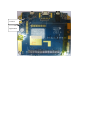
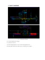
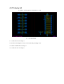
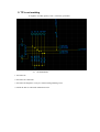
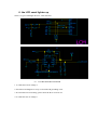
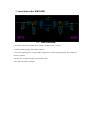
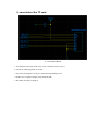
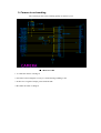
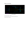
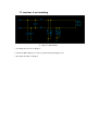
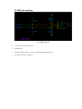
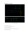
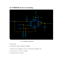
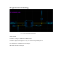
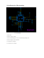
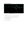
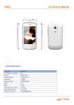
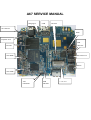
A67 SERVICE MANUAL
Charging IC
USB
BT+FM
TP connector
WIFI
Earphone Jack
26M
FLASH
CRYTAL
CPU-DBB
RF Transceiver
RF PA
CPU-ABB
32K
EMI
CRYSTAL
FILTER
T CARD SLOT
G sensor
Light sensor
1,Canot download/flash SW
It might be the poor quality soldering of IO Connector or CPU, so you should check the soldering
quality of PCBA first ,then check the diagram as below
。
1.use a fresh cable
2.check the I/O connector and its soldering quality
3.re-solder the IO connector
4. re-solder the 32K crystal or change it
5. re-solder the 26M crystal or change it
6. re-solder the flash or change it
7. re-solder the CPU or change it
8.Checking other function diagram
2 Canot power on
Check the positive and negative terminals of the PCBA to verify it is shorted or not; then power
on the handset with DC to verify its current is correct or not; then check the PWR is opened or
not; Re-flash the SW if the current is always 50mA; check the solder quality of 26M crystal or
RF Transceiver if the current is always 10mA.
1, Check the battery connector to verify it is shorted or not; then power on the handset with DC
to verify its current is correct or not;
、 、
2,Re-flash the SW ,check the DM DP U1TXD is shorted with ground or not ;
3,check the current is correct or not, check the LDO,VBAT is shorted with ground or not
4,check the visible component is shorted with ground or not
5,re-solder the 32K crystal or change it
6, re-solder the 26M crystal or change it
7, re-solder the CPU or change it
。
3. CANOT CHARGING
3-1:
CHARGING DIAGRAM
1. Use a fresh USB data cable or charger;
2. re-solder the IO connector
3. check the charging diagram to verify it is shorted with grounding or not
4.Check the solder quality of the VCHG of CPU, re-solder the CPU or change it
4.LCD display fail
It might be soldering quality of EMI filter or LCD
4-1
LCD DIAGRAM
1. re-solder the LCD or change it
2. check the LCD diagram to verify it is shorted with grounding or not
3.re-solder the EMI filter or change it
4. re-solder the CPU or change it
5. TP is not working
It might be assembly quality of TP , or the FPC got broken
5-1
TP DIAGRAM
1. check the TP
2. check the TP connection
3. check the TP diagram to verify it is shorted with grounding or not
4. Check the FPC is connected with PCBA or not
6. the LCD canot lighten up
There is 2 type of backlight driver IC; CPU and other.
6-1
LCD BACKLIGHT DIAGRAM
1. re-solder the LCD or change it
2. check the LCD diagram to verify it is shorted with grounding or not
3. If some LED was not working, please check the Rs is cut off or not
4. re-solder the CPU or change it
7. canot detect the SIM CARD
7-1
SIM DIAGRAM
1. check the connection of SIM card or change a fresh Sim card to verify it
2. Check soldering quality of the SIM connector
3. check the SIM diagram to verify whether component is shorted with grounding , the component
missed or opened;
4. If there was a signal of output, please flash the SW
5. Re-solder the CPU or change it
8. canot detect the TF card
8-1 T-card DIAGRAM
1. checking the connection of TF card, or use a fresh TF card to verify it.
2. Check the soldering quality of TF slot
3. check the TF diagram to verify it is shorted with grounding or not
4. If there was a signal of output, please flash the SW
5. Re-solder the CPU or change it
9. Camera is not working
The Camera got fail or the soldering quality of camera is poor
9-1 CAMERA DIAGRAM
1. re-solder the camera or change it
2. check the Camera diagram to verify it is shorted with grounding or not
3. If there was a signal of output, please flash the SW
4. Re-solder the CPU or change it
10. Mic is not working
10-1 MIC DIAGRAM
1. MIC re-solder the MIC or change it
2. check the MIC diagram to verify it is shorted with grounding or not
3. Re-solder the CPU or change it
11. receiver is not working
11-1 Receiver DIAGRAM
1. Assembly the receiver or change it
2. Check the REC diagram to verify it is shorted with grounding or not
3. Re-solder the CPU or change it
12. SPK not working
12-1 Speaker
电路图
1. re-assembly the SPK or change it
2. flash the SW
3. check the SPK diagram to verify it is shorted with grounding or not
4. Re-solder the CPU or change it
13. Handsfree not working
13-1
Handsfree DIAGRAM
1. use a fresh handsfree to verify it
2. check the soldering quality of handsfree connector
3. check the output signal of hansfree
4. check the hansfree diagram to verify it is shorted with grounding or not
5.re-solder the CPU or change it
14. G SENSOR sensor not working
14-1 G SENSOR DIAGRAM
1. flash the SW
2. Checking the voltage of VDD28 and VDDIO,
3. Check the G sensor diagram to verify it is shorted with grounding or not
4. re-solder the IC of G sensor or change it
5. Re-solder the CPU or change it
15. light sensor not working
15-1 LIGHT SENSOR DIAGRAM
1. flash the SW
2. Check the voltage of VDD28 and VDDIO,VBAT .
3. Check the light sensor diagram to verify it is shorted with grounding or not
4. re-solder the IC of LIGHT sensor or change it
5. Re-solder the CPU or change it
16. the Bluetooth or FM not working
16-1 BT DIAGRAM
1. flash the SW
2. Check the voltage of VBAT
3. Check the BT/FM diagram to verify it is shorted with grounding or not
4. Check the diagram of BT /FM antenna
5. re-solder the IC or change it
6. re-solder the CPU or change it
17. WIFI not working
17-1 WIFI DIAGRAM
1. flash the SW
2. Check the Voltage of VDDWIFI0_3V3
,VDDWIFI1_1V2,VDDSD1
3. Check the WIFI diagram to verify it is shorted with grounding or not
4. Check the diagram of WIFI antenna
5. re-solder the IC or change it
6. re-solder the CPU or change it
18. GSM communication not working
18-1 GSM communication diagram
1. flash the SW
2. Check the voltage of VDDRF0
,VBAT
3. Check the GSM communication diagram to verify it is shorted with grounding or not
4. Check the diagram of GSM antenna
5. re-solder the IC or change it