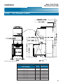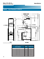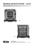
1
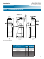
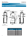
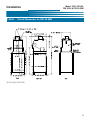
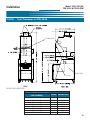
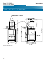
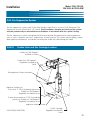
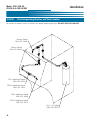
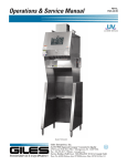
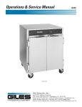
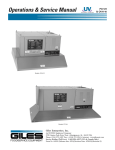
Operations & Service Manual
FSH-2, FSH-2A,
FSH-2A-99, FSH-2A-99W
Model: FSH-2
Giles Enterprises, Inc.
FOODSERVICE EQUIPMENT
An ISO9001 Registered Company
2750 Gunter Park Drive West • Montgomery, AL 36109 USA
Fax: (334) 272-3561 • Internet: www.gilesent.com
Service Hotline (Toll Free): 1-800-554-4537 (USA & Canada Only)
Form No. 60200 (Release date: 07/98)(Revision Date: 11/28/2005)(Rev C)
LIMITED WARRANTY
•
Subject to the terms and conditions of this Limited Warranty as herein stated, all Giles Enterprises,
Inc., Foodservice Equipment and parts purchased new from an authorized Giles Enterprises, Inc.,
representative are warranted as to defects in material or workmanship for a period of 12 months
from the date of installation, provided, however, that with regard to labor costs in connection with
this warranty, see below. All installations must be made by a qualified installing agency in accordance with all applicable codes and/or regulations in the jurisdiction in which installed. Limited warranty coverage is extended to the original owner only and is void if the unit is resold.
•
During the Limited Warranty period, Giles Enterprises, Inc. will replace or recondition, at its factory,
any part or parts of this unit which Giles Enterprises, Inc. inspectors judge defective, provided the
unit has been subjected to normal usage, properly installed, operated and serviced. This Limited
Warranty does not cover cosmetic damage, and damage due to acts of God, accident, misuse, alteration, negligence, abuse of the Giles Foodservice Equipment or the use of unorthodox repair methods. All parts replaced under this Limited Warranty carry only the unexpired term of this Limited
Warranty. Limited Warranty service may be furnished only by an authorized Giles Enterprises, Inc.,
representative.
•
If Limited Warranty service is requested, Giles Enterprises, Inc., will send factory-authorized service representatives to repair, recondition, replace or inspect units of its manufacture with such labor
being rendered without cost to owner for ninety (90) days from the date of installation. Otherwise,
service, including labor and transportation charges or other expenses, in connection with the
removal or installation of any part or parts supplied under this Limited Warranty, are specified on the
original sales contract between the purchaser and the authorized Giles Enterprises, Inc., representative.
•
Giles Enterprises, Inc. reserves the right to change or improve its equipment and parts in any way
without obligation to alter such equipment or parts previously manufactured.
•
Giles Enterprises, Inc. makes no further warranties, express or implied including implied warranties
of merchantability or fitness for a particular purpose, and has no other obligation or liability not
specifically stated herein.
•
Repair or replacement as provided under this Limited Warranty is the exclusive remedy. Giles
Enterprises, Inc., shall not be liable for any incidental or consequential damages for breach of any
express or implied warranty on this product, except to the extent prohibited by applicable law. Any
implied warranty of merchantability or fitness for a particular purpose on this product is limited in
duration to the duration of this Limited Warranty.
•
Used Giles Enterprises, Inc., Foodservice Equipment or parts or Giles Enterprises, Inc., Foodservice
Equipment or parts not purchased from an authorized Giles Enterprises, Inc., representative, carry
no warranties, express or implied.
Table Of Contents
Safety
Model: FSH-2, FSH-2A,
FSH-2A-99, & FSH-2A-99W
........................................................v
Safety Overview . . . . . . . . . . . . . . . . . . . . . . . . . . . . . . . . . . . . . . . . . . . . . . . . . . . . . . . . . . . . . . . . . . . . v
Specific Safety Precautions . . . . . . . . . . . . . . . . . . . . . . . . . . . . . . . . . . . . . . . . . . . . . . . . . . . . . . . . . . . vi
1.
Introduction . . . . . . . . . . . . . . . . . . . . . . . . . . . . . . . . . . . . . . . . . . . . . . 1
1-01.
1-02.
1-03.
1-03.
1-03.01.
1-03.02.
1-03.03.
1-03.04.
1-03.04.
1-03.06.
Construction . . . . . . . . . . . . . . . . . . . . . . . . . . . . . . . . . . . . . . . . . . . . . . . . . . . . . . . . . . . . . . 1
Standard Features. . . . . . . . . . . . . . . . . . . . . . . . . . . . . . . . . . . . . . . . . . . . . . . . . . . . . . . . . . 1
Optional Feature . . . . . . . . . . . . . . . . . . . . . . . . . . . . . . . . . . . . . . . . . . . . . . . . . . . . . . . . . . . 1
Specifications . . . . . . . . . . . . . . . . . . . . . . . . . . . . . . . . . . . . . . . . . . . . . . . . . . . . . . . . . . . . . 2
Overall Dimensions for FSH-2 . . . . . . . . . . . . . . . . . . . . . . . . . . . . . . . . . . . . . . . . . . . . . . . . 2
Overall Dimensions for FSH-2A . . . . . . . . . . . . . . . . . . . . . . . . . . . . . . . . . . . . . . . . . . . . . . . 3
Overall Dimensions for FSH-2A-99. . . . . . . . . . . . . . . . . . . . . . . . . . . . . . . . . . . . . . . . . . . . . 4
Overall Dimensions for FSH-2A-99W . . . . . . . . . . . . . . . . . . . . . . . . . . . . . . . . . . . . . . . . . . . 5
Regulatory Listings . . . . . . . . . . . . . . . . . . . . . . . . . . . . . . . . . . . . . . . . . . . . . . . . . . . . . . . . . 6
Unit Weights . . . . . . . . . . . . . . . . . . . . . . . . . . . . . . . . . . . . . . . . . . . . . . . . . . . . . . . . . . . . . . 6
2.
Installation . . . . . . . . . . . . . . . . . . . . . . . . . . . . . . . . . . . . . . . . . . . . . . . 7
2-01.
2-02.
2-03.
2-03.01.
2-03.02.
2-03.03.
2-03.04.
2-04.
2-04.01.
2-04.02.
2-04.03.
2-04.04.
2-04.05.
2-04.06.
2-05.
2-05.01.
2-05.02.
2-05.03.
2-06.
Location . . . . . . . . . . . . . . . . . . . . . . . . . . . . . . . . . . . . . . . . . . . . . . . . . . . . . . . . . . . . . . . . . 7
Unpacking . . . . . . . . . . . . . . . . . . . . . . . . . . . . . . . . . . . . . . . . . . . . . . . . . . . . . . . . . . . . . . . . 8
Electrical Requirements . . . . . . . . . . . . . . . . . . . . . . . . . . . . . . . . . . . . . . . . . . . . . . . . . . . . . 8
Electrical Connections (Overview) . . . . . . . . . . . . . . . . . . . . . . . . . . . . . . . . . . . . . . . . . . . . . 9
Hood Power Connection. . . . . . . . . . . . . . . . . . . . . . . . . . . . . . . . . . . . . . . . . . . . . . . . . . . . . 9
Hood and Appliance Interlock Connection . . . . . . . . . . . . . . . . . . . . . . . . . . . . . . . . . . . . . . 10
Fire Alarm Connection . . . . . . . . . . . . . . . . . . . . . . . . . . . . . . . . . . . . . . . . . . . . . . . . . . . . . 11
Fryer and Oven Limitations and clearances . . . . . . . . . . . . . . . . . . . . . . . . . . . . . . . . . . . . . 11
Fryer Limitations under FSH-2, FSH-2A, FSH-2A-99. . . . . . . . . . . . . . . . . . . . . . . . . . . . . . . 11
Oven Limitations under FSH-2A-99W . . . . . . . . . . . . . . . . . . . . . . . . . . . . . . . . . . . . . . . . . 12
Fryer Clearances for FSH-2. . . . . . . . . . . . . . . . . . . . . . . . . . . . . . . . . . . . . . . . . . . . . . . . . . 13
Fryer Clearances for FSH-2A . . . . . . . . . . . . . . . . . . . . . . . . . . . . . . . . . . . . . . . . . . . . . . . . 14
Fryer Clearances for FSH-2A-99 . . . . . . . . . . . . . . . . . . . . . . . . . . . . . . . . . . . . . . . . . . . . . . 15
Oven Clearances for FSH-2A-99W . . . . . . . . . . . . . . . . . . . . . . . . . . . . . . . . . . . . . . . . . . . . 16
Fire Suppression System . . . . . . . . . . . . . . . . . . . . . . . . . . . . . . . . . . . . . . . . . . . . . . . . . . . 17
Fusible Links and Gas Cartridge Location. . . . . . . . . . . . . . . . . . . . . . . . . . . . . . . . . . . . . . . 17
Fire Exinguishing Nozzles and Tank Location . . . . . . . . . . . . . . . . . . . . . . . . . . . . . . . . . . . . 18
Manual Pull Diagram. . . . . . . . . . . . . . . . . . . . . . . . . . . . . . . . . . . . . . . . . . . . . . . . . . . . . . . 19
Restraining Device . . . . . . . . . . . . . . . . . . . . . . . . . . . . . . . . . . . . . . . . . . . . . . . . . . . . . . . . 20
3.
Overview . . . . . . . . . . . . . . . . . . . . . . . . . . . . . . . . . . . . . . . . . . . . . . . 21
3-01.
3-02.
3-03.
Filter Area . . . . . . . . . . . . . . . . . . . . . . . . . . . . . . . . . . . . . . . . . . . . . . . . . . . . . . . . . . . . . . . 22
Control Panel . . . . . . . . . . . . . . . . . . . . . . . . . . . . . . . . . . . . . . . . . . . . . . . . . . . . . . . . . . . . 24
Accessories (Included) . . . . . . . . . . . . . . . . . . . . . . . . . . . . . . . . . . . . . . . . . . . . . . . . . . . . . 26
iii
Model: FSH-2, FSH-2A,
FSH-2A-99, & FSH-2A-99W
Table Of Contents
4.
Operation . . . . . . . . . . . . . . . . . . . . . . . . . . . . . . . . . . . . . . . . . . . . . . . 29
4-01.
4-02.
4-02.01.
4-02.02.
4-02.03.
4-02.04.
4-02.05.
4-02.06.
4-02.07.
4-02.08.
4-02.09.
4-02.10.
4-02.11.
4-02.12.
4-02.13.
4-03.
4-03.01.
4-03.02.
4-03.03.
4-03.04.
4-03.05.
4-03.06.
Hood Operation . . . . . . . . . . . . . . . . . . . . . . . . . . . . . . . . . . . . . . . . . . . . . . . . . . . . . . . . . . 29
Hood Filters and Filter Maintenance . . . . . . . . . . . . . . . . . . . . . . . . . . . . . . . . . . . . . . . . . . 29
Hood Filter Table . . . . . . . . . . . . . . . . . . . . . . . . . . . . . . . . . . . . . . . . . . . . . . . . . . . . . . . . . . 29
Baffle Filter Removal. . . . . . . . . . . . . . . . . . . . . . . . . . . . . . . . . . . . . . . . . . . . . . . . . . . . . . . 30
Baffle Filter Installation . . . . . . . . . . . . . . . . . . . . . . . . . . . . . . . . . . . . . . . . . . . . . . . . . . . . . 31
Baffle Filter Missing . . . . . . . . . . . . . . . . . . . . . . . . . . . . . . . . . . . . . . . . . . . . . . . . . . . . . . . 32
Baffle Filter Cleaning Procedure . . . . . . . . . . . . . . . . . . . . . . . . . . . . . . . . . . . . . . . . . . . . . . 32
EAC Filter Removal . . . . . . . . . . . . . . . . . . . . . . . . . . . . . . . . . . . . . . . . . . . . . . . . . . . . . . . . 32
EAC Filter Installation . . . . . . . . . . . . . . . . . . . . . . . . . . . . . . . . . . . . . . . . . . . . . . . . . . . . . . 33
EAC Filter Status. . . . . . . . . . . . . . . . . . . . . . . . . . . . . . . . . . . . . . . . . . . . . . . . . . . . . . . . . . 33
EAC Fitler Cleaning . . . . . . . . . . . . . . . . . . . . . . . . . . . . . . . . . . . . . . . . . . . . . . . . . . . . . . . . 34
Charcoal Filter Removal . . . . . . . . . . . . . . . . . . . . . . . . . . . . . . . . . . . . . . . . . . . . . . . . . . . . 35
Charcoal Filter Installaton . . . . . . . . . . . . . . . . . . . . . . . . . . . . . . . . . . . . . . . . . . . . . . . . . . . 35
Charcoal Filter Missing . . . . . . . . . . . . . . . . . . . . . . . . . . . . . . . . . . . . . . . . . . . . . . . . . . . . . 36
Charcoal Replacement Procedure . . . . . . . . . . . . . . . . . . . . . . . . . . . . . . . . . . . . . . . . . . . . 36
Maintenance . . . . . . . . . . . . . . . . . . . . . . . . . . . . . . . . . . . . . . . . . . . . . . . . . . . . . . . . . . . . . 37
Monthly Interlock Check . . . . . . . . . . . . . . . . . . . . . . . . . . . . . . . . . . . . . . . . . . . . . . . . . . . . 37
Quarterly Hood Cleaning . . . . . . . . . . . . . . . . . . . . . . . . . . . . . . . . . . . . . . . . . . . . . . . . . . . 37
Semi-Annual Fire Suppression System Servicing. . . . . . . . . . . . . . . . . . . . . . . . . . . . . . . . . 38
Annual Fire Suppression System Servicing . . . . . . . . . . . . . . . . . . . . . . . . . . . . . . . . . . . . . 38
Twelve Year Suppression System Servicing . . . . . . . . . . . . . . . . . . . . . . . . . . . . . . . . . . . . . 38
Maintenance and Service Log . . . . . . . . . . . . . . . . . . . . . . . . . . . . . . . . . . . . . . . . . . . . . . . 39
5.
Hood Cleaning . . . . . . . . . . . . . . . . . . . . . . . . . . . . . . . . . . . . . . . . . . . 41
5-01.
Cleaning . . . . . . . . . . . . . . . . . . . . . . . . . . . . . . . . . . . . . . . . . . . . . . . . . . . . . . . . . . . . . . . . 41
6.
Troubleshooting . . . . . . . . . . . . . . . . . . . . . . . . . . . . . . . . . . . . . . . . . 43
6-01.
Troubleshooting Procedures . . . . . . . . . . . . . . . . . . . . . . . . . . . . . . . . . . . . . . . . . . . . . . . . . 43
7.
Parts List . . . . . . . . . . . . . . . . . . . . . . . . . . . . . . . . . . . . . . . . . . . . . . . 45
7-01.
7-02.
7-03.
Parts Ordering and Service Information . . . . . . . . . . . . . . . . . . . . . . . . . . . . . . . . . . . . . . . . 45
Ventless Hood -Front . . . . . . . . . . . . . . . . . . . . . . . . . . . . . . . . . . . . . . . . . . . . . . . . . . . . . . 46
Ventless Hood -Rear . . . . . . . . . . . . . . . . . . . . . . . . . . . . . . . . . . . . . . . . . . . . . . . . . . . . . . . 48
8.
Wiring Diagrams . . . . . . . . . . . . . . . . . . . . . . . . . . . . . . . . . . . . . . . . . 51
8-01.
8-02.
8-03.
Wiring Diagram FSH-2, FSH-2A, FSH-2A-99, FSH-2A-99W 208-240/60/1 . . . . . . . . . . . . . . 52
Wiring Diagram FSH-2, FSH-2A, FSH-2A-99, FSH-2A-99W 208-240/60/1 w/ILS . . . . . . . . . 54
Wiring Diagram FSH-2, FSH-2A, FSH-2A-99, FSH-2A-99W 220/50/1 . . . . . . . . . . . . . . . . . 56
iv
Model: FSH-2, FSH-2A,
FSH-2A-99, & FSH-2A-99W
Safety
Safety
Safety Overview
The instructions contained in this manual have been prepared to aid you in learning the proper procedures
for installing and servicing your new unit.
Throughout this manual, safety precautions are identified through the use of the safety alert symbol and
three signal words: DANGER, WARNING, and CAUTION. All safety alert information precedes the
step(s) to which they apply. Suggested, recommended, or other noteworthy information is identified
through the use of NOTES. Additionally, certain words are used to indicate a specific meaning or to add
emphasis.
The following words are used as indicated throughout the manual:
Shall: understood to be mandatory.
Should: understood to be advisory.
May: understood to be permissive.
Will: indicates a future event/condition to occur.
! or !
Used in conjunction with signal words (DANGER, WARNING, or CAUTION) to alert you of potential personal injury hazards, immediately preceding precautionary measures that pertain to subsequent step(s).
Obey all safety messages that follow this symbol to avoid possible injury or death. Failure to adhere to
safety precautions identified by the safety alert symbol may also void the warranty.
!
DANGER
• Indicates an imminently hazardous situation which, if not avoided, will result in death or serious injury.
! WARNING
• Indicates a potentially hazardous situation which, if not avoided, could result in death or serious injury.
! CAUTION
• Indicates a potentially hazardous situation which, if not avoided, may result in minor or moderate injury.
Also used to alert against unsafe practices.
CAUTION
• When used without the safety alert symbol, CAUTION indicates a potentially hazardous situation which,
if not avoided, may result in equipment/property damage, and void the warranty.
NOTE:
• Identifies suggested, recommended, or other noteworthy information.
v
Model: FSH-2, FSH-2A,
FSH-2A-99, & FSH-2A-99W
Safety
Specific Safety Precautions
For your safety, please observe the following precautions when operating or servicing your Giles equipment. Read the following important safety information to avoid personal injury and/or damage to the
equipment.
!
DANGER
•
Turn off the unit and unplug the power cord before cleaning or performing maintenance.
•
DO NOT hose down the unit’s interior or exterior with water.
•
Failure to comply with these DANGER notices will result in death or serious injury, equipment/property damage,
and void the warranty.
! WARNING
•
Consult a qualified electrician to ensure that:
•• all electrical specifications and codes are met.
•• circuit breakers and wiring are of sufficient rating and gauge.
•
The unit must be properly grounded and all electrical specifications must be met during installation.
•
Improper installation, adjustment, alteration, service or maintenance could result in death or serious injury, equipment/property damage, and void the warranty.
•
DO NOT use or store gasoline or other flammable liquids or vapors in the vicinity of this or any other appliance!
•
Failure to comply with WARNING notices could result in death or serious injury and equipment/property damage
and void the warranty.
! CAUTION
•
The unit must remain in the upright (vertical) position.
•
Exercise care when removing the wooden crate from around the unit.
•
DO NOT operate the unit unless you fully understand the components and their intended function (see Section
3).
vi
Safety
Model: FSH-2, FSH-2A,
FSH-2A-99, & FSH-2A-99W
! CAUTION
•
The unit must be adequately and properly grounded. Improper grounding may result in electrical shock.
Always refer to your local electrical code to ensure proper grounding of this or any other electrical equipment. Always consult with an electrician or other qualified service person to ensure breakers and wiring are
of sufficient rating and gauge for the equipment being operated.
•
Ensure the unit is positioned in a secure, safe location.
•
Consult an electrician to ensure all electrical specifications have been met and the unit is properly grounded. The
wiring diagrams contained in this manual should aid your electrician in the installation of your unit.
CAUTION
•
The electronic components of the Control Panel are impact-sensitive. Exercise care around the Control Panel to
maintain proper operation.
•
DO NOT install the unit next to combustible walls and materials. Failure to maintain safe distances may result in
fire.
•
During cleaning of the unit
•• DO NOT steam clean.
•• DO NOT use products containing chlorine.
•• DO NOT use abrasive products, steel wool or scouring pads.
•
DO NOT modify, alter or add attachments to this equipment!
•
Failure to comply with these CAUTION notices may result in equipment/property damage and void the warranty.
NOTE:
•
If the crate is damaged upon receipt, immediately inspect the unit and notify the carrier of any damage to the
unit.
•
To aid the electrician, an electrical wiring diagram is contained in this manual. Refer to the wiring diagram during
installation or servicing.
•
Comply with all appropriate state and/or local heath regulations regarding the cleaning and sanitation of equipment.
vii
Model: FSH-2, FSH-2A,
FSH-2A-99, & FSH-2A-99W
Notes:
viii
Safety
Introduction
1.
Model: FSH-2, FSH-2A,
FSH-2A-99, & FSH-2A-99W
Introduction
Congratulations on the purchase of your new Giles Free Standing Ventless Hood, Model FSH-2, FSH-2A,
FSH-2A-99 or FSH-2A-99W manufactured by Giles Enterprises, Inc., Montgomery, Alabama (USA), hereafter referred to as "Giles". The Free Standing Ventless Hood is a product of extensive research and testing. Every unit is thoroughly inspected and tested prior to shipment. Proper care and maintenance will
ensure years of trouble-free service.
The Giles Ventless Hood System is used in conjunction with various listed cooking appliances to accomplish removal of grease vapors and objectionable odors which may be generated during cooking. The hood
system performs this function through the use of what is commonly referred to as an electronic air cleaner (EAC). Electronic air cleaners use an electrical charge to remove contaminant's from the air as they
pass through the EAC.
To help protect your investment in this equipment, we recommend taking a few moments to familiarize
yourself with the installation, cleaning and maintenance procedures contained in this manual. Read these
instructions before installation and use. Adherence to these recommended procedures minimizes the
potential for costly "down-time" and equipment repairs. Please retain this manual for future reference.
1-01. Construction
All of the unit’s exterior parts are constructed of stainless steel.
1-02. Standard Features
Three Stage Filtration -uses three different filters to remove particulate matter from the air.
Extinguishing System -built into the hood to extinguish an accidental fire from the Fryer installed
underneath the hood.
1-03. Optional Feature
Interlocking Start System (ILS) -Interlocking Start System (ILS) -This system will cause the Hood and
the Appliance below the Hood to shut down when the hood filters need
to be cleaned or are not properly installed. ILS is required by some
cities and/or states. Please check with your local code officials to see if
this system is required.
1
Model: FSH-2, FSH-2A,
FSH-2A-99, & FSH-2A-99W
1-03. Specifications
1-03.01.
Overall Dimensions for FSH-2
INCHES [MILLIMETERS]
DOCKING OPENING WIDTH “X”
MODEL (LETTER DESIGNATION
INCHES MILLIMETERS
FOR OPENING)
FSH-2 (A)
24
609.6
FSH-2 (B)
20-1/8
511.2
FSH-2 (C)
18-5/8
473.1
FSH-2 (D)
16-1/8
409.6
FSH-2 (E)
15-5/8
396.9
FSH-2 (F)
15-1/8
384.2
FSH-2 (G)
14-1/8
358.8
FSH-2 (H)
10-1/8
257.2
2
Introduction
Model: FSH-2, FSH-2A,
FSH-2A-99, & FSH-2A-99W
Introduction
1-03.02.
Overall Dimensions for FSH-2A
INCHES [MILLIMETERS]
DOCKING OPENING WIDTH “X”
MODEL (LETTER DESIGNATION
INCHES MILLIMETERS
FOR OPENING)
FSH-2A (A)
24
609.6
FSH-2A (B)
20-1/8
511.2
FSH-2A (C)
18-5/8
473.1
FSH-2A (D)
16-1/8
409.6
FSH-2A (E)
15-5/8
396.9
FSH-2A (F)
15-1/8
384.2
FSH-2A (G)
14-1/8
358.8
FSH-2A (H)
10-1/8
257.2
3
Model: FSH-2, FSH-2A,
FSH-2A-99, & FSH-2A-99W
1-03.03.
Overall Dimensions for FSH-2A-99
INCHES [MILLIMETERS]
DOCKING OPENING WIDTH “X”
MODEL (LETTER DESIGNATION
INCHES MILLIMETERS
FOR OPENING)
FSH-2 (A)
24
609.6
FSH-2 (B)
20-1/8
511.2
FSH-2 (C)
18-5/8
473.1
FSH-2 (D)
16-1/8
409.6
FSH-2 (E)
15-5/8
396.9
FSH-2 (F)
15-1/8
384.2
FSH-2 (G)
14-1/8
358.8
FSH-2 (H)
10-1/8
257.2
4
Introduction
Introduction
1-03.04.
Model: FSH-2, FSH-2A,
FSH-2A-99, & FSH-2A-99W
Overall Dimensions for FSH-2A-99W
INCHES [MILLIMETERS]
5
Model: FSH-2, FSH-2A,
FSH-2A-99, & FSH-2A-99W
1-03.04.
Introduction
Regulatory Listings
UL (US and Canada)
NSF
CE
1-03.06.
Unit Weights
Weights
Crated
Model
6
Uncrated
lb
kg
lb
kg
FSH-2
462
146
327
148
FSH-2A
609
277
454
206
FSH-2A-99
535
243
380
173
FSH-2A-99W
635
289
480
218
Installation
Model: FSH-2, FSH-2A,
FSH-2A-99, & FSH-2A-99W
2. Installation
This section provides a summary of the procedures necessary for proper installation of your unit. To help prevent personal injury or equipment damage, please ensure the following steps are taken.
2-01. Location
NOTE:
•The decibel level of the hood when operating is approximately 65 dB’s.
! CAUTION
•
DO NOT MODIFY, ALTER OR ADD ATTACHMENTS TO THIS EQUIPMENT
1.
Before unpacking the unit and assembling the unit, using the dimensions and clearances shown in
Section 2-04.03. and 2-04.06, determine the location of the unit.
2.
Keep the unit and the surrounding area free and clear from combustible materials.
3.
Please provide adequate room for servicing and proper operation of the unit. Also, provide
adequate ventilation in the operating area where necessary.
4.
Before operating, make sure the unit is in a secure position and will not move.
7
Model: FSH-2, FSH-2A,
FSH-2A-99, & FSH-2A-99W
Installation
2-02. Unpacking
Your unit may arrive enclosed by a wooden crate. The Hood is secured to a wooden platform by means of
high-tensile strength strapping.
NOTE:
• If the crate is damaged, immediately inspect the unit and notify the carrier of any damage to the
unit.
! CAUTION
•
•
•
Exercise care when lifting or moving the unit.
Exercise care when removing the wooden crate from around the unit.
Failure to comply with these CAUTION notices may result in minor or moderate injury, equipment/property damage, and void the warranty.
1.
Carefully cut and remove the plastic shipping wrap and the strapping mentioned above.
2.
Use pliers to loosen wire hooks which secure the wooden crate around the unit. Remove the
wooden crate.
3.
Carefully remove the unit from the shipping platform. Your new FSH-2, FSH-2A, FSH-2A-99, or FSH2A-99W is extremely heavy, see Section 1-03.04. for unit weights. Great care should be taken in lifting or moving the unit to prevent personal injury or equipment damage.
2-03. Electrical Requirements
! WARNING
•
Consult a qualified electrician to ensure all electrical specifications have been met and that the unit is properly
grounded.
•
The unit must be adequately and properly grounded. Improper grounding may result in electrical
shock. Always refer to your local electrical code to ensure proper grounding of this or any other
electrical equipment. Always consult with an electrician or other qualified service person to
ensure breakers and wiring are of sufficient rating and gauge for the equipment being operated.
•
Improper installation, adjustment, alteration, service or maintenance could result in death or serious injury, equipment/property damage, and void the warranty.
Hood Electrical Requirements
8
Unit
Voltage
Hz
Phase
Amps
Breaker
FSH-2
208-240
60
1
3
10
FSH-2A
208-240
60
1
3
10
FSH-2A-99
208-240
60
1
3
10
FSH-2A-99W
208-240
60
1
3
10
Model: FSH-2, FSH-2A,
FSH-2A-99, & FSH-2A-99W
Installation
2-03.01.
Electrical Connections (Overview)
Fire Alarm Tie-In Box
Interlock Tie-In Box
Service Entrance
Box
Connection to
Appliance
2-03.02.
Hood Power Connection
Connect Hood Power:
1.
Install appropriate Circuit Breakers in Hood Supply Power Box (Main Breaker Box). See Section 2-03.
for required Circuit Breakers.
2.
Remove Cover on Service Entrance Box and run appropriate size conduit and wire from the Service
Entrance Box to the Hood Supply Power box (Main Breaker Box). Allow enough conduit and wire so
the unit can be accessed for cleaning and servicing.
3.
Make all appropiate connections.
4.
Reinstall Service Entrance Box Cover.
9
Model: FSH-2, FSH-2A,
FSH-2A-99, & FSH-2A-99W
2-03.03.
Installation
Hood and Appliance Interlock Connection
This connection will cause the Appliance installed below the Hood to shut down if any of the following
occurs:
• Any Filter becomes excessively dirty, not allowing proper air flow through the Hood.
• Any Filter is missing or not installed correnctly
• The Fire Extinguisher System is activated.
Interlock Hood to Appliance:
1.
Remove Cover on Interlock Tie-In Box and run appropriate size conduit and wire from the Interlock
Tie-In Box to a Hood and Appliance Connection Box (Supplied by Customer). Allow enough conduit
and wire so the Hood can be accessed for cleaning and servicing.
2.
Make appropiate connections. See Diagram below.
3.
Reinstall Interlock Tie-In Box Cover.
NOTE:
• If not using the ILS option, the Hood will continue to run and the Appliance will turn off when:
•
Any Filter becomes excessively dirty, not allowing proper air flow through the Hood.
•
Any Filter is missing or not installed correctly.
•
The Fire Extinguisher System is activated.
•
10
If using the ILS option, the Hood and Appliance will turn off when:
•
Any Filter becomes excessively dirty, not allowing proper air flow through the Hood.
•
Any Filter is missing or not installed correctly.
•
The Fire Extinguisher System is activated.
Model: FSH-2, FSH-2A,
FSH-2A-99, & FSH-2A-99W
Installation
2-03.04.
Fire Alarm Connection
This connection will send a signal the Facility Fire Alarm System that the Hood Fire Extinguisher System
has been activated.
Fire Alarm Connection:
1.
Remove Cover on Fire Alarm Tie-In Box and run appropriate size conduit and wire from the Box to
the Facility Fire Alarm System. Allow enough conduit and wire so the Hood can be accessed for
cleaning and servicing.
2.
Make appropiate connections.
3.
Reinstall Fire Alarm Tie-In Box Cover.
2-04. Fryer and Oven Limitations and clearances
This section describes various limitations to the fryers and the oven that can be placed underneath the
hoods. Please note only Electic Fryers and Oven that do not exceed the following limitations and following
clearances are approved to be placed under these hoods. Gas Fryers, Gas Ovens, or any other type of
appliances are not approved.
2-04.01.
Fryer Limitations under FSH-2, FSH-2A, FSH-2A-99
! WARNING
•
These Hoods are design for Electric Fryers Only!!! DO NOT USE ANY GAS APPLIANCES UNDER THE FSH2, FSH-2A, FSH-2A-99!!!
Hood
Max. kW Input
Max. Shortening
Capacity (lbs)
Max Cooking Surface
(per Fryer)
FSH-2
20 (Fryers only)
110
380 Sq. In.
FSH-2A
20 (Fryers only)
110
380 Sq. In.
FSH-2A-99
20 (Fryers only)
110
380 Sq. In.
11
Model: FSH-2, FSH-2A,
FSH-2A-99, & FSH-2A-99W
2-04.02.
Installation
Oven Limitations under FSH-2A-99W
! WARNING
•
12
This Hood is design for Electric Ovens Only!!! DO NOT USE ANY GAS APPLIANCES UNDER THE
FSH-2A-99W!!!
Hood
Max. kW Input
Max. Oven Temperature
FSH-2A-99W
8 (Ovens only)
450F
Model: FSH-2, FSH-2A,
FSH-2A-99, & FSH-2A-99W
Installation
2-04.03.
Fryer Clearances for FSH-2
Fusible Link
Fryer Only
Fry Vat
INCHES [MILLIMETERS]
DOCKING OPENING WIDTH “X”
MODEL (LETTER DESIGNATION
INCHES MILLIMETERS
FOR OPENING)
FSH-2 (A)
24
609.6
FSH-2 (B)
20-1/8
511.2
FSH-2 (C)
18-5/8
473.1
FSH-2 (D)
16-1/8
409.6
FSH-2 (E)
15-5/8
396.9
FSH-2 (F)
15-1/8
384.2
FSH-2 (G)
14-1/8
358.8
FSH-2 (H)
10-1/8
257.2
13
Model: FSH-2, FSH-2A,
FSH-2A-99, & FSH-2A-99W
2-04.04.
Installation
Fryer Clearances for FSH-2A
Fusible Link
Fryer Only
Fry Vat
INCHES [MILLIMETERS]
DOCKING OPENING WIDTH “X”
MODEL (LETTER DESIGNATION
INCHES MILLIMETERS
FOR OPENING)
FSH-2A (A)
24
609.6
FSH-2A (B)
20-1/8
511.2
FSH-2A (C)
18-5/8
473.1
FSH-2A (D)
16-1/8
409.6
FSH-2A (E)
15-5/8
396.9
FSH-2A (F)
15-1/8
384.2
FSH-2A (G)
14-1/8
358.8
FSH-2A (H)
10-1/8
257.2
14
Model: FSH-2, FSH-2A,
FSH-2A-99, & FSH-2A-99W
Installation
2-04.05.
Fryer Clearances for FSH-2A-99
Fusible Link
Fryer Only
Fry Vat
INCHES [MILLIMETERS]
DOCKING OPENING WIDTH “X”
MODEL (LETTER DESIGNATION
INCHES MILLIMETERS
FOR OPENING)
FSH-2A-99 (A)
24
609.6
FSH-2A-99 (B)
20-1/8
511.2
FSH-2A-99 (C)
18-5/8
473.1
FSH-2A-99 (D)
16-1/8
409.6
FSH-2A-99 (E)
15-5/8
396.9
FSH-2A-99 (F)
15-1/8
384.2
FSH-2A-99 (G)
14-1/8
358.8
FSH-2A-99 (H)
10-1/8
257.2
15
Model: FSH-2, FSH-2A,
FSH-2A-99, & FSH-2A-99W
2-04.06.
Installation
Oven Clearances for FSH-2A-99W
Fusible Link
INCHES [MILLIMETERS]
16
Model: FSH-2, FSH-2A,
FSH-2A-99, & FSH-2A-99W
Installation
2-05. Fire Suppression System
The fire suppression system used in your Giles Ventless Hood Fryer is an Ansul R-102 Restaurant Fire
Suppression System (Standard UL 197 Listed). Final installation, charging and testing of the system
must be performed by an authorized Ansul distributor in accordance with the system’s listing.
The fire suppression system is designed and UL-listed to provide fire protection for cooking appliances
such as fryers. It protects your units, automatically, 24 hours per day. The system contains piping, nozzles
(both appliance and plenum), and conduit for routing the fusible link cable through the hood.
2-05.01.
Fusible Links and Gas Cartridge Location
Fusible Link 285 Degree F
Installed at Factory
Fusible Link 165 Degree F
Supplied & Installed by
Ansul
See Appliance Fusible Link below
Appliance Fusible Link:
If less than 3” [76.2] to cooking surface use
Fusible Link 165 Degree F
Supplied & Installed by Ansul
If more than or equal to 3” [76.2] to cooking
surface use Fusible Link 135 Degree F
Supplied & Installed by Ansul
Appliance Cooking Surface
INCHES [MILLIMETERS]
LT-20 R Cartridge
Supplied & Installed by
Ansul
17
Model: FSH-2, FSH-2A,
FSH-2A-99, & FSH-2A-99W
2-05.02.
Installation
Fire Exinguishing Nozzles and Tank Location
All nozzles have been factory installed in the proper operating position. DO NOT MOVE OR ADJUST.
Plenum Nozzle
Giles P/N 46426
Plenum Nozzle
Giles P/N 46426
FSH-2 Appliance Nozzle
Giles P/N 46426
FSH-2A Appliance Nozzle
Giles P/N 40131
FSH-2 Appliance Nozzle
Giles P/N 46426
FSH-2A Appliance Nozzle
Giles P/N 40131
Tank, 1-1/2 Gallon
Giles P/N 39272
18
Installation
2-05.03.
Model: FSH-2, FSH-2A,
FSH-2A-99, & FSH-2A-99W
Manual Pull Diagram
This Hood requires use of the Ansul R-102 Standard for a Manual Pull System. The Manual Pull System
must be mounting on a near-by wall and connect to the Hood. This Manual Pull System is used to active
the Fire Extinguisher System from a remote location. The Manual Pull System is supplied and installed by
Ansul.
The following illustration is a typical Manual Pull installation. Using this basic configuration the Hood may
be moved from the wall for Cleaning and Servicing without removing the Manual Pull from the wall.
1/2 Conduit from Hood
90 Degree Pulley
Ansul Manual Pull
Assembly mounted
on the wall
90 Degree Pulley
19
Model: FSH-2, FSH-2A,
FSH-2A-99, & FSH-2A-99W
Installation
2-06. Restraining Device
Any Fryer placed under this Hood must be secured so that the Fryer can not move from below the Hood.
The following is an example of a restraining device that may be used. The appropiate restaining device will
vary depending on the Fryer, the restaining device is not supplied with the hood.
Note: Be sure to maintain minumum and maximum clearances (see Section 2-04.02 or 2-04.03
after the Restraining Device is installed.
20
Overview
Model: FSH-2, FSH-2A,
FSH-2A-99, & FSH-2A-99W
3. Overview
The following section provides a brief overview of the components, functions, and accessories of the Free
Standing Hood, Model FSH-2, FSH-2A, FSH-2A-99 and FSH-2A-99W. Please review this section carefully
before proceeding any further.
Filter Area
Figure 3-01.
Control Panel
Figure 3-02.
Appliance Centering Bracket
Fryer or Oven Area (Fryer or
Oven not shown)
21
Model: FSH-2, FSH-2A,
FSH-2A-99, & FSH-2A-99W
Overview
3-01. Filter Area
7
*1
2
3
6
5
8
4
* -Not Shown
22
Model: FSH-2, FSH-2A,
FSH-2A-99, & FSH-2A-99W
Overview
3-01. Filter Area
Item
Description
*1
Hood Filter Cover
2
Charcoal Filter
3
EAC Filter
Function
Used to access the Electronic Air Cleaner (EAC) and
Charcoal Filters. This cover must be in place and
latched for the unit to operate.
This Filter helps to remove odors generated during cooking. This Filter should be replaced monthly. NEVER
attempt to clean a Charcoal Filter. Keep a spare filter
on hand (Giles 30248) for quick change-out when needed! DO NOT remove the Charcoal Filter while the
Hood or the Fryer is operating to prevent contact
with electrical parts and avoid electrical shock.
The EAC Filter is an electrical device which removes
grease vapor and smoke generated by the fryer during
cooking. Power must be turned OFF to the Hood and
Fryer before removing the EAC for cleaning.The EAC
should be cleaned daily. DO NOT remove the EAC
Filter while the Hood or the Fryer is operating to prevent contact with electrical parts and avoid electrical
shock.
The Baffle Filter is the first stage of the grease extraction
and air-cleaning system found on these units. It is easily
removed for daily cleaning. DO NOT remove the Baffle
Filter while the Hood or the Fryer is operating to prevent contact with electrical parts and avoid electrical
shock.
4
Baffle Filter
5
Grease Drip Cup
6
Grease Drip Cup Safety Pin
Used to hold the Grease Drip Cup in place and to prevent the cup from accidentally dropping
7
Exhaust Stack
Located on top of the unit. Allow the recommended
clearance of 18” or a minimum clearance of 12”
between the top of the Exhaust Stack and the ceiling.
8
Appliance Fusible Link
Used to detect a fire in the Fryer Vat. Be careful not to
hit or bump this link. Doing so may inadvertently
cause the Fire Extinguisher System to activate.
Used to hold excess grease from the hood. This cup
should be cleaned daily or as needed.
* -Not Shown
23
Model: FSH-2, FSH-2A,
FSH-2A-99, & FSH-2A-99W
Overview
3-02. Control Panel
1
2
3
4
5
6
*8
7
24
Model: FSH-2, FSH-2A,
FSH-2A-99, & FSH-2A-99W
Overview
3-02. Control Panel
Item
Description
Function
1
ON Indicator Light
(EAC Status)
Used to indicate the Electronic Air Cleaner (EAC) Filter is on or
powered.
2
WASH Indicator Light
(EAC Status)
Used to indicate the EAC has become excessively dirty. Do
not rely upon this light as a signal for routine cleaning of the
EAC. Failure to clean the EAC daily will significantly decrease
the life of the charcoal filter. Clean the EAC daily for best performance.
3
CHECK Indicator Light
(EAC Status)
Used to indcate the EAC Filter is no longer cleaning the air.
The EAC Filter must be cleaned or repaired.
4
Hood Powered
Indicator Light
Used to indicate the Hood is powered and running.
5
Fryer Powered
Indicator Light
Used to indicate power is available to the Fryer under the
hood.
6
Filter Missing
Indicator Light
Used to indicate the Baffle Filter or Charcoal Filter is missing
or not correctly in place.
7
Power Switch
Used to turn power on to the Hood and will allow the Fryer
under the Hood to be turned on.
*8
Push and Hold to Start
Button
(Used with ILS (Interlocking Start) units only). Used after the
Power Switch is in the “ON” position, push and hold down
“PUSH AND HOLD TO START” Button for 5 seconds allowing the unit to start. This allows the Hood and the Fryer
underneath to both shut down if the Hood Filters become
excessively dirty.
This option is required by some cities. Please contact your
local code officials to see if this is required in your city.
* - Not Shown
25
Model: FSH-2, FSH-2A,
FSH-2A-99, & FSH-2A-99W
3-03.
Accessories (Included)
Part
26
Overview
Description/Part Number
Function
Baffle Filter
P/N 42300
Used for removing smoke and
contaminants from the air
EAC Filter
P/N 20520
Used for removing smoke and
contaminants from the air
Charcoal Filter
P/N 30248
Used for removing odors from
the air
Model: FSH-2, FSH-2A,
FSH-2A-99, & FSH-2A-99W
Overview
3-03. Accessories (Included)
Part
Description/Part Number
Function
EAC Soak Tank
P/N 39327
Used for cleaning EAC filter.
27
Model: FSH-2, FSH-2A,
FSH-2A-99, & FSH-2A-99W
Notes:
28
Overview
Model: FSH-2, FSH-2A,
FSH-2A-99, & FSH-2A-99W
Operation
4. Operation
This section describes the operation of and the filter maintenance for the Hood.
4-01. Hood Operation
This section describes how to start the Ventless Hood. Make sure all the Filters are in place before operating the unit.
3
1. Press the Power Switch to the ON 1 position, (if ILS, then
press and hold the “Push and Hold to Start” 2 switch, for 5
seconds), the following will occur:
4
3 - illuminates indicating the EAC filter is cleaning the air.
5
4 - illuminates indicating the Hood is on and powered.
*2
5 - illuminates indicating power is available to the Fryer
underneath the Hood.
1
* -ILS only
2. The Fryer underneath the Hood may now be turned on and
used.
4-02. Hood Filters and Filter Maintenance
This section describes each Filter and it’s maintenance required.
4-02.01.
Hood Filter Table
Filter
When to clean or
replace
How to remove
How to clean
How to install
Baffle Filter
Clean daily
Section 4-02.06
Section 4-02.07
Section 4-02.08
EAC Filter
Clean daily
Section 4-02.08
Section 4-02.11
Section 4-02.09
Charcoal Filter
Replace every 30
days,
P/N 30248
Section 4-02.12.
Never clean, only
replace
Section 4-02.15
Section 4-02.13.
29
Model: FSH-2, FSH-2A,
FSH-2A-99, & FSH-2A-99W
4-02.02.
Operation
Baffle Filter Removal
BA
FFL
EF
ILT
ER
BAF
FLE
FIL
TER
1
2
BAF
FLE
FIL
TER
3
TER
LE FIL
BAFF
4
30
Model: FSH-2, FSH-2A,
FSH-2A-99, & FSH-2A-99W
Operation
4-02.03.
Baffle Filter Installation
2
3
BAF
FLE
FIL
TER
TER
LE FIL
BAFF
1
BAF
FLE
FIL
TER
4
BA
FFL
EF
ILT
ER
Switch arm
must be
actuated by
the Baffle
Filter as
shown
31
Model: FSH-2, FSH-2A,
FSH-2A-99, & FSH-2A-99W
4-02.04.
Operation
Baffle Filter Missing
If the Baffle Filter is missing or not in place correctly the Filter
Missing Light 1 will come on. See Section 7-02.03 Baffle Filter
Installation.
1
4-02.05.
Baffle Filter Cleaning Procedure
The Baffle Filter should be cleaned daily. Place the Baffle Filter in a sink and clean with a mild degreaser.
Dry thoroughly, then reinstall in the unit.
4-02.06.
EAC Filter Removal
Hood Filter Cover
EAC
EAC
32
Model: FSH-2, FSH-2A,
FSH-2A-99, & FSH-2A-99W
Operation
4-02.07.
EAC Filter Installation
Hood Filter Cover
Filter must align
with this pin
EAC
EAC
EAC Air Flow Arrow locatated
on the left or right of the EAC
Handle and must point up
4-02.08.
EAC Filter Status
The three indicator lights on the Control Panel display the status of the EAC Filter.
1 ON
The EAC Filter is in place and powered.
2 WASH
The EAC Filter is becoming excessively dirty and must be cleaned. If this
light is on for more then 2 minutes an
intermittent alarm will sound, and
power to the Fryer underneath the
Hood will be turned off.
1
2
3
3 CHECK The EAC Filter is not operating, either
the filter is not properly connected to
the power source or it is damaged. If
this light is on for more then 2 minutes an intermittent alarm will sound,
and power to the Fryer underneath
the Hood will be turned off.
33
Model: FSH-2, FSH-2A,
FSH-2A-99, & FSH-2A-99W
4-02.09.
Operation
EAC Fitler Cleaning
! CAUTION
• Do not bend the fins or break the ionizer wires on the EAC as this will prevent the EAC from
working properly and potentially void the warranty.
Fins
Ionizer Wires
(9) Required
1. Mix 1/2 Gallon of a mild non-caustic biodegradable degreaser, such
as Simple Green or Clean Magic, with 6.5 gallons of water in the
included Soak Tank 1 .
NOTE:
• The mixed solution in the Soak Tank should last up to 30 days
without being changed.
2
3
2. Holding the contact plate 2 on the EAC 3 slowly lower the filter into the Soak Tank.
3. After allowing the EAC to soak for 20 to 30 minutes, using the contact plate 2 , lift the EAC up and down approximately 1” to 2” to
help remove the grease residue.
1
4. Slowly remove the EAC from the tank and rinse clean in a sink
using hot water.
5. Allow the EAC to air dry, thoroughly.
CAUTION
• Do not dry the EAC either by running the hood to air dry or by running the appliance to heat dry.
This could potentially damage the EAC causing improper operation and voiding the warranty.
34
Model: FSH-2, FSH-2A,
FSH-2A-99, & FSH-2A-99W
Operation
4-02.10.
Charcoal Filter Removal
Hood Filter Cover
CH
AR
CO
AL
CH
AR
CO
AL
4-02.11.
Charcoal Filter Installaton
Hood Filter Cover
Switch must be actuated
by the filter
CH
AR
CO
AL
CH
AR
CO
AL
35
Model: FSH-2, FSH-2A,
FSH-2A-99, & FSH-2A-99W
4-02.12.
Operation
Charcoal Filter Missing
If the Charcoal Filter is missing or not correctly in place the Filter
Missing Light 1 will come on. See Section 4-02.11 Charcoal Filter
Installation.
1
4-02.13.
Charcoal Replacement Procedure
CAUTION
• Never attempt to clean the Charcoal Filter. Replace the Filter. The reuse of a Charcoal Filter can
cause damage to the unit.
Replace the Charcoal Filter every 30 days. Use Replacement Part No. 30248.
36
Operation
Model: FSH-2, FSH-2A,
FSH-2A-99, & FSH-2A-99W
4-03. Maintenance
This Section describes periodic maintenance for the Ventless Hood System. Performance of these procedures will maintain the unit’s efficiency over time.
A Maintenance and Service Log is provided in this manual, see Section 4-03.06.
4-03.01.
Monthly Interlock Check
Your Giles Ventless Hood System incorporates an Interlock System to ensure the unit is operated in a safe
and effective manner. Testing of the Interlock System should be conducted MONTHLY in the following manner. Use the form located in Section 4-06.06 Maintenance and Service Log, place a check in the box that corresponds to the test being performed. If a problem is found, call your service representative.
1.
Baffle Filter Check-With the Power Switch in the “OFF” position remove the grease baffle. Place
the Power Switch in the “ON” position. Check appliance power underneath the Hood, the appliance
should not turn on. Turn the Power Switch to the “OFF” position and reinstall the grease baffle into
the hood.
2.
EAC Filter Check-With the Power Switch in the “OFF” position remove the EAC. Place the Power
Switch in the “ON” position, wait two minutes. Check appliance power underneath the Hood, the
appliance should not turn on. Reinstall the EAC.
3.
Charcoal Filter Check-With the Power Switch in the “OFF” position remove the Charcoal Filter.
Place the Power Switch in the ”ON” position. Check appliance power underneath the Hood, the
appliance should not turn on. Return the Power Switch to the “OFF” position. Reinstall the charcoal
filter.
4.
Filter Clogged Check-Place the Power Switch in the “ON” position. Place a piece of cardboard
over half the Grease Baffle Filter. Check appliance power underneath the Hood, the appliance
should not turn on.. A buzzer will sound in approximately two minutes if the cardboard is not
removed. Return Power Switch to the “OFF” position. Remove the cardboard.
4-03.02.
Quarterly Hood Cleaning
CAUTION
•
During cleaning of the unit
•• DO NOT steam clean.
•• DO NOT use products containing chlorine.
•• DO NOT use abrasive products, steel wool or scouring pads.
Remove power from the unit. Remove the Hood Filter Cover and all Filters from the hood. Using a mild
degreaser clean the entire Hood Plenum and Blower Sections. The hood must be cleaned every 3
months.
37
Model: FSH-2, FSH-2A,
FSH-2A-99, & FSH-2A-99W
4-03.03.
Operation
Semi-Annual Fire Suppression System Servicing
Service of the Fire Suppression System is to be conducted by qualified fire equipment personnel. As a minimum,
field inspection of the Fire Suppression System is to be accomplished semi-annually by qualified fire equipment
service personnel. Such maintenance shall consist of the following (Consult the Giles Enterprises Design
Installation, Recharge and Maintenance Manual for complete servicing guidelines).
Place fire extinguishing system locking bar on fire system when servicing hood.
1. Remove charging cartridge, inspect gasket for cuts and elasticity, coat gasket with extreme temperature grease and reinstall. See Section 2-06.01. Fusible Link and Gas Cartridge Locations
2. Remove tank, verify chemical is at proper level, clean and coat O-ring with extreme temperature
grease and reinstall. See Section 2-06.02. Fire Extinguisher Nozzle and Tank Locations
3. Check all nozzles to insure they are free of cooking grease buildup.
4. Test the remote manual pull station for activation and wear.
5. Install test link and cut to simulate automatic actuation.
6. Clean and inspect fusible links.See Section 2-06.01. for Fusible Link and Gas Cartridge Locations
7.
Inspect wire rope for wear at pulleys and detectors and replace if necessary.
8. Record maintenance date and maintain in a permanent file.
4-03.04.
Annual Fire Suppression System Servicing
Same as Semi-Annual but all fusible links must be replaced with new fusible links. See Section 2-06.01.
Fusible Link and Gas Cartridge Locations.
4-03.05.
Twelve Year Suppression System Servicing
Same as Annual except for the following.
1. Replace R-102 fire suppression chemical.
2. Hydrostatically test the tank and cartridge.
3. Flow test the regulator.
38
Model: FSH-2, FSH-2A,
FSH-2A-99, & FSH-2A-99W
Operation
4-03.06.
Check
Maintenance and Service Log
Initial/Date Check
1
2
3
4
ABC 1/2/03
1
2
1
2
3
4
1
2
1
2
3
4
5
1
2
1
2
3
4
1
2
1
2
3
4
1
2
1
2
3
4
5 6*
1
2
1
2
3
4
1
2
1
2
3
4
1
2
1
2
3
4
5
1
2
1
2
3
4
1
2
1
2
3
4
1
2
1
2
3
4
5 6* 7*
1
2
1
2
3
4
1
2
1
2
3
4
1
2
1
2
3
4
5
1
2
1
2
3
4
1
2
1
2
3
4
1
2
1
2
3
4
5 6*
1
2
1
2
3
4
1
2
1
2
3
4
1
2
1
2
3
4
5
1
2
1
2
3
4
1
2
1
2
3
4
1
2
1
2
3
4
5 6* 7*
1
2
1
2
3
4
1
2
1
2
3
4
1
2
1
2
3
4
5
1
2
1
2
3
4
1
2
1
2
3
4
1
2
1
2
3
4
5 6*
1
2
1
2
3
4
1
2
1
2
3
4
5
1
2
1
2
3
4
5
1
2
1
2
3
4
5
1
2
1
2
3
4
5
1
2
1
2
3
4
5 6* 7*
1
2
1 Baffle Filter Check
2 EAC Filter Check
4 Filter Clogged
5 Quarterly Cleaning
7 Fire Suppression System replace Fusible Links
Initial/Date
3
3
3
3
3
3
3
3
3
3
3
3
3
3
3
3
3
3
3
3
3
3
3
3
3
3
3
3
3
3
3
3
3
3
3
3
4
4
4
4
4
4
4
4
4
4
4
4
4
4
4
4
4
4
4
4
4
4
4
4
4
4
4
4
4
4
4
4
4
4
4
4
5
5
6*
5
5
6*
7*
5
5
6*
5
5
6*
7*
5
5
6*
5
5
6*
7*
3 Charcoal Filter Check
6 Fire Suppression System
* Inspection performed by a qualified fire equipment company.
39
Model: FSH-2, FSH-2A,
FSH-2A-99, & FSH-2A-99W
Notes:
40
Operation
Hood Cleaning
Model: FSH-2, FSH-2A,
FSH-2A-99, & FSH-2A-99W
5. Hood Cleaning
This section describes the cleaning of the hood. The hood must be cleaned every 3 months.
5-01. Cleaning
Interior -Disconnect power to the unit. Remove the Filter Cover and all Filters from the hood. Using a
soft cloth, sponge or towel and a mild non-caustic biodegradable degreaser, clean the entire Hood
Plenum area and Filter Channels.
Exterior -remove power from the unit. Using a stainless steel cleaner, clean all external stainless steel
parts.
Filters -To clean and replace Filters, see Section 4.02.01 Hood Filter Table.
41
Model: FSH-2, FSH-2A,
FSH-2A-99, & FSH-2A-99W
Notes:
42
Hood Cleaning
Model: FSH-2, FSH-2A,
FSH-2A-99, & FSH-2A-99W
Troubleshooting
6. Troubleshooting
This section describes troubleshooting procedures for the FSH-2, FSH-2A, FSH-2A-99, FSH-2A-99W.
Refer to the wiring diagrams in Section 8 for more detailed analysis.
!
•
DANGER
Electrical troubleshooting procedures should be performed ONLY by qualified service personnel.
Death or serious injury will result from contact with energized electrical components.
• Failure to comply with these DANGER notices will result in death or serious injury, equipment/property
damage, and void the warranty.
6-01. Troubleshooting Procedures
Problem
Hood will not turn on
Probable Cause
a. (ILS only) “Push and Hold”
button not held for 5 seconds
b. Power switch bad
Filter Missing Light on
Check or Wash Light on
Repair Procedure
a. Hold down “Push and Hold”
button until unit remains
running
b. Replace power switch.
c. Improper supply voltage
c. Connect to proper voltage
source.
d. Hood cover not closed
d. Close hood cover.
e. Not connected to power
source
e. Connect to proper power
source.
f.
f.
Circuit breaker tripped
Reset Circuit breaker.
a. Baffle filter is not installed
a. Install Baffle filter.
b. Charcoal filter is not installed
b. Install charcoal filter.
a. EAC shorted
a. Replace or repair EAC.
b. EAC dirty
b. Clean EAC.
c. High voltage power supply
faulty.
c. Replace high voltage power
supply
d. High voltage wires shorted.
d. Correct shorted condition.
e. Bad contact plate
e. Replace contact plate.
43
Model: FSH-2, FSH-2A,
FSH-2A-99, & FSH-2A-99W
Troubleshooting
6-01. Troubleshooting Procedures (Cont’d.)
Problem
Probable Cause
Repair Procedure
Fryer or Oven will not turn on
a. Baffle Filter missing
a. Install Baffle Filter
• Hood Power Light on
• Filter Missing Light on
b. Baffle Filter not installed
properly
b. Reinstall Baffle Filter
c. Charcoal Filter missing
c. Install Charcoal Filter
a. Charcoal Filter clogged
a. Replace Charcoal Filter
Fryer or Oven will not turn on
• Hood Power Light on
• Buzzer emitting a continuous tone b. Baffle Filter clogged
• Fryer Powered light off
b. Clean Baffle Filter
c. Vacuum switch out of
adjustment
c. Adjust Vacuum switch only.
d. Kinked vacuum line
d. Remove vacuum line kinks
e. Fan running slow
e. Check voltage
Fryer or Oven will not turn on
a. EAC shorted
a. Repair EAC
• Hood Power Light on
• Buzzer emitting a pulsating tone
• Fryer Powered Light off
b. EAC dirty
b. Clean EAC
c. EAC power supply faulty
c. Replace EAC power supply
d. EAC wires shorted
d. Check voltage
e. Bad contact plate
e. Replace contact plate
f.
f.
EAC module faulty
g. EAC ionizer wire broken or
missing
44
Replace EAC module
g. Replace ionizer wire
Parts List
7.
Model: FSH-2, FSH-2A,
FSH-2A-99, & FSH-2A-99W
Parts List
This section lists various parts that are available for replacement on the FSH2, FSH-2A, FSH-2A-99, and
FSH-2A-99W.
7-01. Parts Ordering and Service Information
If you require assistance or need repairs, please contact your area developer for a service agency in your
area. For further assistance, please contact the Giles Enterprises, Inc. factory at the following phone
numbers:
IN THE UNITED STATES, CANADA or MEXICO
Please call 1-800-288-1555 during normal business hours, 8:00AM-5:00PM Central Time Zone. For emergency equipment repair service, after normal business hours, call 1-800-288-1555, extension 314.
IN ALL OTHER COUNTRIES
Please call 1-334-272-3528 during normal business hours, 8:00AM-5:00PM Central Time Zone; For emergency equipment repair service, after normal business hours call, 1-334-272-3528 extension 314.
INTERNET
Please visit our website on the world wide web at: www.gilesent.com.
The goal of the Giles team of professionals is to provide you with the highest quality of service and assistance. You can help us accomplish this by obtaining the following information and having it readily available when calling. The information is recorded on the Serial Plate attached to the rear of the unit.
Serial Plate information
The area below may be helpful in recording information for use as a quick reference.
Model:
______________________________________
Serial Number: ______________________________________
Phase:
___________________________________________
Voltage: ___________________________________________
45
Model: FSH-2, FSH-2A,
FSH-2A-99, & FSH-2A-99W
Parts List
7-02. Ventless Hood -Front
3
2
*4
*1
*5
6
9
7
11
14
15
**10
8
13
* -Not shown
46
12
Model: FSH-2, FSH-2A,
FSH-2A-99, & FSH-2A-99W
Parts List
7-02. Parts List for Front Ventless Hood -Front
Item No.
Part No.
Qty.
Description
*1
39041
1
HOOD FILTER ACCESS PANEL, ASSY
2
20520
1
FILTER, EAC, 20 IN
3
30248
1
FILTER, CHARCOAL, ASSY, 20 X 12.375 X 2
*4
23200
1
SWITCH, SNAP ACTION, ROLLER TYP
*5
21125
1
BOARD, CONTACT, EAC, VH UNITS
6
30206
1
DRIP CUP, WELD ASSY
7
34750
1
PIN, DRIP CUP SAFETY
8
42300
1
FILTER, BAFFLE, 20X20, S/S, LARGE VH
9
24209
1
LED, AIR FILTER, EAC
**10
23173
1
SWITCH, MOMENTARY
11
22277
1
INDICATOR LIGHT, GREEN
12
21190
1
SWITCH, ROCKER, ON-OFF, 250V, 20A, DPST
13
64460
1
LABEL, CONTROL PANEL, FSH-2
14
38213
1
INDICATOR LIGHT, ORANGE
15
38214
1
INDICATOR LIGHT, RED
* -Not shown
** -Not shown and ILS only
47
Model: FSH-2, FSH-2A,
FSH-2A-99, & FSH-2A-99W
Parts List
7-03. Ventless Hood -Rear
5
4
6
8
*3 *2
12
11
10
1
15
9
14
13
* -Not shown
** -Not shown, ILS only
48
7
Model: FSH-2, FSH-2A,
FSH-2A-99, & FSH-2A-99W
Parts List
7-03. Parts List for Ventless Hood -Rear
Item No.
Part No.
Qty.
Description
1
39272
1
TANK, 1.5 GAL. & LABEL ASSY.
*2
23778
1
SWITCH, SIDE ROTARY, 240V, 30A, W/O ARM
*3
23779
1
ROD, ADJUSTMENT
4
33589
1
BLOWER, ASSY, VH-FRYERS
5
46125
1
DAMPER, FIRE, 10 X 10, 285 DEG LINK
6
24237
1
SWITCH, PLUNGER, 250V, 15A
7
23001
1
SWITCH, VACUUM, HOSE BARB
8
20002
1
SWITCH, ANSUL, SHUTDOWN/ALARM, 15A, 120V
9
40132
1
BRACKET & RELEASE, ANSUL
10
23776
1
MODULE, AIR FILTER, ALARM AND SHUTDOWN
11
24208
1
POWER SUPPLY, W/DRIVER BRD, 208-240V,EAC
12
23751
1
TERMINAL BLOCK, MA106
13
23782
1
SONALERT, 250V, CONTINUOUS BEEP
14
22950
1
SONALERT, 250V, INTERMITTENT
15
21191
1
RELAY, 30A, 208V, 2PL
15
21174
1
RELAY, 30A, 240V, 2PL
* -Not shown
** -Not shown, ILS only
49
Model: FSH-2, FSH-2A,
FSH-2A-99, & FSH-2A-99W
Notes:
50
Parts List
Wiring Diagram
Model: FSH-2, FSH-2A,
FSH-2A-99, & FSH-2A-99W
8. Wiring Diagrams
The following section contains various Wiring Diagrams for the FSH-2, FSH-2A, FSH-2A-99, and
FSH-2A-99W. Please check the Serial Plate, as shown below, for the units Model Name, Voltage, Hertz,
and Phase.
Serial Plate
51
Model: FSH-2, FSH-2A,
FSH-2A-99, & FSH-2A-99W
8-01.
Wiring Diagram
Wiring Diagram FSH-2, FSH-2A, FSH-2A-99, & FSH-2A-99W 208-240/60/1
WIRING DIAGRAM P/N:
32353-F
52
Model: FSH-2, FSH-2A,
FSH-2A-99, & FSH-2A-99W
Wiring Diagram
8-01.
Parts List for Wiring Diagram FSH-2, FSH-2A, FSH-2A-99, & FSH-2A-99W 208-240/60/1
Item
Part No.
1
2
3
4
5
6
7
8
9
10
11
12
13
14
15
16
17
18
19
20
21
22
23
24
21125
24208
23001
38215
23751
33589
24300
21190
24237
21174
32114
23776
23200
23782
22950
21182
24209
20002
--------20298
25275
38214
38213
Qty.
1
1
1
1
1
1
2
1
1
1
1
1
1
1
1
1
1
1
1
1
1
2
1
1
Description
BOARD, CONTACT, EAC, VH UNITS
POWER SUPPLY, W/DRIVER BRD, 208-240V,EAC
SWITCH, VACUUM, HOSE BARB
INDICATOR LIGHT, GREEN
TERMINAL BLOCK, MA106,6 POLE
BLOWER, ASSY, CF-400VH, CF-500VH
BOX, 1/2" UTILITY
SWITCH, ROCKER, ON-OFF, 250V, 20A, DPST
SWITCH, PLUNGER, 250V, 15A
RELAY, 30A, 240V, 2 POLE
BAFFLE FILTER SWITCH, ASSY, CF-400/500VH
MODULE, AIR FILTER, ALARM AND SHUTDOWN
SWITCH, SNAP ACTION, ROLLER TYPE
SONALERT, 250V, CONTINUOUS BEEP
SONALERT, 250V, INTERMITTENT
SWITCH, PRESSURE, FIREBUTLER, 40PSI
LED, AIR FILTER, EAC
SWITCH, ANSUL, SHUTDOWN/ALARM, 15A, 120V
CONTACTOR
LOAD CENTER
BRAID, COPPER SHIELDING
WIRENUT, IDEAL BLUE
INDICATOR LIGHT, ORANGE
INDICATOR LIGHT, RED
53
Model: FSH-2, FSH-2A,
FSH-2A-99, & FSH-2A-99W
8-02.
Wiring Diagram
Wiring Diagram FSH-2, FSH-2A, FSH-2A-99, & FSH-2A-99W 208-240/60/1 w/ILS
WIRING DIAGRAM P/N:
33802-D
54
Model: FSH-2, FSH-2A,
FSH-2A-99, & FSH-2A-99W
Wiring Diagram
8-02. Parts List for Wiring Diagram FSH-2, FSH-2A, FSH-2A-99, & FSH-2A-99W 208-240/60/1 w/ILS
Item
01
02
03
04
05
06
07
08
09
10
11
12
13
14
15
16
17
18
19
20
21
22
23
24
25
Part No.
21125
24208
23001
38215
23751
33589
24300
21190
24237
21174
32114
23776
23200
23782
22950
21182
24209
20002
--------23173
20298
25275
38214
38213
Qty.
1
1
1
1
1
1
2
1
1
1
1
1
1
1
1
1
1
1
1
1
1
1
1
1
1
Description
BOARD, CONTACT, EAC, VH UNITS
POWER SUPPLY, W/DRIVER BRD, 208-240V,EAC
SWITCH, VACUUM, HOSE BARB
INDICATOR LIGHT, GREEN
TERMINAL BLOCK, MA106,6 POLE
BLOWER, ASSY, CF-400VH, CF-500VH
BOX, 1/2" UTILITY
SWITCH, ROCKER, ON-OFF, 250V, 20A, DPST
SWITCH, PLUNGER, 250V, 15A
RELAY, 30A, 240V, 2 POLE
BAFFLE FILTER SWITCH, ASSY, CF-400/500VH
MODULE, AIR FILTER, ALARM AND SHUTDOWN
SWITCH, SNAP ACTION, ROLLER TYPE
SONALERT, 250V, CONTINUOUS BEEP
SONALERT, 250V, INTERMITTENT
SWITCH, PRESSURE, FIREBUTLER, 40PSI
LED, AIR FILTER, EAC
SWITCH, ANSUL, SHUTDOWN/ALARM, 15A, 120V
CONTACTOR
LOAD CENTER
SWITCH,PUSHBUTTON,N.O.,MOM,PLUNGER
BRAID, COPPER SHIELDING
WIRENUT, IDEAL BLUE
INDICATOR LIGHT, ORANGE
INDICATOR LIGHT, RED
55
Model: FSH-2, FSH-2A,
FSH-2A-99, & FSH-2A-99W
8-03.
Wiring Diagram
Wiring Diagram FSH-2, FSH-2A, FSH-2A-99, & FSH-2A-99W 220/50/1
WIRING DIAGRAM P/N:
36306-D
56
Model: FSH-2, FSH-2A,
FSH-2A-99, & FSH-2A-99W
Wiring Diagram
8-03. Parts List for Wiring Diagram FSH-2, FSH-2A, FSH-2A-99, & FSH-2A-99W220/50/1
Item
1
2
3
4
5
6
7
8
9
10
11
12
13
14
15
16
17
18
19
20
21
22
23
24
Part No.
21125
24208
23001
22277
23751
33589
24300
21190
24237
21174
32114
23776
23200
23782
22950
21182
24209
20002
--------20298
25275
20298
25275
Qty.
1
1
1
1
1
1
2
1
1
1
1
1
1
1
1
1
1
1
1
1
1
1
1
1
Description
BOARD, CONTACT, EAC, VH UNITS
POWER SUPPLY, W/DRIVER BRD, 208-240V,EAC
SWITCH, VACUUM, HOSE BARB
INDICATOR LIGHT, GREEN
TERMINAL BLOCK, MA106,6 POLE
BLOWER, ASSY, CF-400VH, CF-500VH
BOX, 1/2" UTILITY
SWITCH, ROCKER, ON-OFF, 250V, 20A, DPST
SWITCH, PLUNGER, 250V, 15A
RELAY, 30A, 240V, 2 POLE
BAFFLE FILTER SWITCH, ASSY, CF-400/500VH
MODULE, AIR FILTER, ALARM AND SHUTDOWN
SWITCH, SNAP ACTION, ROLLER TYPE
SONALERT, 250V, CONTINUOUS BEEP
SONALERT, 250V, INTERMITTENT
SWITCH, PRESSURE, FIREBUTLER, 40PSI
LED, AIR FILTER, EAC
SWITCH, ANSUL, SHUTDOWN/ALARM, 15A, 120V
CONTACTOR
LOAD CENTER
BRAID, COPPER SHIELDING
WIRENUT, IDEAL BLUE
INDICATOR LIGHT, ORANGE
INDICATOR LIGHT, RED
57
Model: FSH-2, FSH-2A,
FSH-2A-99, & FSH-2A-99W
Notes:
58
Wiring Diagram
FOODSERVICE EQUIPMENT
Giles Enterprises, Inc.
P.O. Box 210247 • 2750 Gunter Park Drive West • Montgomery, Al 36121-0247 USA
(334) 272-1457 • Service Hotline 1-800-554-4537 (USA & Canada Only) • FAX (334) 272-3561 • www.gilesent.com
Form No. 60200 (Release date: 07/98)(Revision date: 11/28/2005)(Rev C)(ECO1006)(CSY)