Download Digital Oscilloscopes DL9040/DL9040L
Transcript
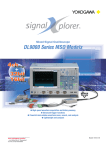
Digital Oscilloscopes
DL9040 / DL9040L
!
W
NE
Introducing New Models of the DL9000 Series
High-speed Digital Sampling Oscilloscopes for Midrange Bandwidths
l500 MHz bandwidth with up to 5 G samples/sec
lHigh acquisition rates
• Continuous mode (when the accumulation function is used):
Up to 25,000 frames/sec for each channel
• N Single mode: Up to 2.5 million frames/sec for each channel
lHistory memory
• The large-capacity memory can be partitioned to automatically
accumulate and display up to 2,000 waveform frames.
Large-capacity Memory and High acquisition rates!
• The DL9040/9040L constantly updates and stores up to 2,000 of
the most-recent waveform frames.
• In continuous acquisition mode, the DL9040/9040L updates the
display at the exceptionally high rate of 25,000 frames/sec.
lThin and compact
• A thin (only 18 cm), compact, and lightweight (only 6.5 kg)
design makes the DL9040/9040L easy to carry around.
DL9000 Series Model Selection Table
Model Name
Frequency bandwidth
Maximum sampling rate
Memory size
http://www.yokogawa.co.jp/tm/
... and subscribe to “Newswave,”
our free e-mail newsletter
W!
DL9040/DL9040L NE
500MHz
5GS/s
DL9040: 2.5MW
DL9040L: 6.25MW
DL9140 / DL9140L
1.0GHz
5GS/s
DL9140: 2.5MW
DL9140L: 6.25MW
DL9240 / DL9240L
1.5GHz
10GS/s
DL9240: 2.5MW
DL9240L: 6.25MW
Bulletin 7013-50E
Specifications
Models
Model name (No.)
DL9040 (701307)
DL9040L (701308)
Trigger Section
Max. sampling rate
5 GS/s
5 GS/s
Freq. bandwidth
500 MHz
500 MHz
Max. record length
2.5 MW
6.25 MW
Basic Specifications
Input channels
Input coupling
Input impedance
4 (CH1 to CH4)
AC, DC, GND, DC50Ω
1 MΩ ±1.0% approx. 20 pF (when using PB500 probe, 10 MΩ
±2.0%, approx. 14 pF)
50 Ω ±1.5%
Voltage axis sensitivity For 1 MΩ input: 2 mV/div to 5 V/div (steps of 1-2-5)
ranges
For 50 Ω input: 2 mV/div to 500 mV/div (steps of 1-2-5)
Maximum input voltage For 1 MΩ input: 150 Vrms CAT I (Less than 1 kHz)
For 50 Ω input: 5 Vrms or less and 10 Vpeak or less
DC offset max. setting range For 1 MΩ input
(When probe attenuation set to 1:1)
2 mV/div to 50 mV/div:
±1 V
100 mV/div to 500 mV/div: ±10 V
1 V/div to 5 V/div:
±100 V
For 50 Ω input
2 mV/div to 50 mV/div:
±1 V
100 mV/div to 500 mV/div: ±5 V
Vertical (voltage) axis sensitivity
DC accuracy1
For 1 MΩ input: ±(1.5% of 8 div + offset voltage accuracy)
For 50 Ω input: ±(1.5% of 8 div + offset voltage accuracy)
1
Offset voltage axis accuracy
2 mV/div to 50 mV/div:
±(1% of setting + 0.2 mV)
100 mV/div to 500 mV/div: ±(1% of setting + 2 mV)
1 V/div to 5 V/div:
±(1% of setting + 20 mV)
Frequency characteristics1, 2 For 50 Ω input, For 1 MΩ input (from the probe tip when using
the dedicated passive probe (PB500))
(Attenuation point of -3 dB when inputting a sinewave of amplitude ±2 div or equivalent)
5 V/div to 10 mV/div:
DC to 500 MHz
5 mV/div to 2 mV/div: DC to 400 MHz
3
Residual noise level
0.4 mV rms or 0.05 div rms, whichever is larger (typical value)
A/D conversion resolution 8-bit (25 LSB/div)
Bandwidth limit
For each channel, select FULL, 200 MHz, 20 MHz, 8 MHz,
4 MHz, 2 MHz, 1 MHz, 500 kHz, 250 kHz, 125 kHz, 62.5 kHz,
32 kHz, 16 kHz, 8 kHz.
Max. sampling rate
Real time sampling mode
Interleave mode ON:
5 GS/s
Interleave mode OFF:
2.5 GS/s
Repetitive sampling mode:
2.5 TS/s
Model and Suffix Codes
Model
Suffix Codes
701307
Description
Digital Oscilloscope DL9040
4 ch, 500 MHz, max. 5 GS/s (2.5 GS/s/ch),
2.5 Mword/ch
701308
Digital Oscilloscope DL9040L
4 ch, 500 MHz, max. 5 GS/s (2.5 GS/s/ch),
6.25 Mword/ch
701310
Digital Oscilloscope DL9140
4 ch, 1 GHz, max. 5 GS/s (2.5 GS/s/ch),
2.5 Mword/ch
701311
Digital Oscilloscope DL9140L
4 ch, 1 GHz, max. 5 GS/s (2.5 GS/s/ch),
6.25 Mword/ch
701312
Digital Oscilloscope DL9240
4 ch, 1.5 GHz, max. 10 GS/s (5 GS/s/ch),
2.5 Mword/ch
701313
Power cable
Help menu language
-D
-F
-Q
-R
-H
-HE
-HC
/B5
/P2 1
Options
/C10 2
/C8 2
/F5 3
Digital Oscilloscope DL9240L
4 ch, 1.5 GHz, max. 10 GS/s (5 GS/s/ch),
6.25 Mword/ch
UL/CSA standard
VDE standard
BS standard
AS standard
GB standard
English Help
Chinese Help
Built-in printer
Probe power connections on rear panel
(2 outputs for current probes, differential probes)
Ethernet interface
Built-in HDD + Ethernet interface
I2C + SPI bus analyzer
1: Please order /P2 option if you use either current probes or differential probes from Yokogawa. For 2.5 GHz
active probe and 5 GHz low capacitence probe, this option is not necessary.
2: Choose either one
3: I2C and SPI triggers are standard. This will be available later Please contact Yokogawa for detail.
Trigger modes
Trigger source
Window comparator
Trigger types
Event Interval
Enhanced
Auto, Auto Level, Normal, Single, and N Single
CH1 to CH4, LINE, EXT
Channels CH1 to CH4, or individual channels
Edge/State:
Edge, Edge (Qualified), Edge OR, State
Width:
Pulse, Pulse (Qualified), Pulse State
Event Cycle, Event Delay, Event Sequence
TV (NTSC, PAL, HDTV, USER)/I2C, SPI (3 wire, 4 wire), Serial pattern
Display
Display
8.4-inch color TFT liquid crystal display
Functions
Waveform Acquisition/Display Functions
Acquisition modes
Select from three acquisition modes: Normal, Envelope, and
Average.
Other acquisition modes High resolution mode, Repetitive sampling mode, Interleave
mode, Interpolate mode
Interpolate function
Interpolates actual sampled data by up to 1000 times (or up to
2000 times in High-Res. mode) and increases the time
resolution (up to 2.5 TS/s)
X-Y
displays XY1, XY2 and T-Y simultaneously
Accumulation
Accumulates waveforms on the display. Choose Count/Time
and Inten/Color.
Snapshot
Retains the current displayed waveform on the screen.
Analysis Functions
Search and Zoom function
Zooms the displayed waveform along the time (Horizontal
Zoom) and voltage (Vertical Zoom) axes. Independent zooming
factors can be applied to two zoom areas.
Search types: Edge, Edge Qualified, State, Pulse, Pulse
Qualified, Pulse State, Serial Pattern, I2C
(optional), SPI (optional)
History memory
DL9040L: 2000 wareforms (2.5 kW)
DL9040: 1000 wareforms (2.5 kW)
Cursor measurements Vertical, Horizontal, VT, Marker, Serial
Automatic measurement of Waveform Parameters function
MAX, MIN, HIGH, LOW, P-P, HIGH-LOW, +OVER, -OVER,
RMS, MEAN, Sdev, IntegTY
C.rms, C.mean, C.Sdev, C.IntegTY, (1/FREQ), FREQ, COUNT,
BURST
+WIDTH, -WIDTH, PERIOD, DUTY, RISE, FALL, DELAY
Telecom Test
Performs mask test and eye pattern measurement
Computation functions Computes up to eight traces (CH1-CH4/M1-M4)
Reference functions
Display and analysis (computation and cursors) on up to four
traces (M1-M4) of the saved waveform data.
Action-on-trigger
Modes:
OFF, All Condition, (GO/NOGO Zone/Param), GO/
NOGO Telecom Test)
Actions: Buzzer, Print, Save, Mail
Optional Functions
Built-in Printer (/B5 Option)
Internal Hard Disk Drive (/C8 Option)
Ethernet Communication (/C10 and /C8 Option)
I2C + SPI Bus Analysis Function (/F5 Option)
1. Measured value under standard operating conditions after 30-minute warm-up and performing
calibration.
Standard operating conditions: Ambient temperature:
23 ±5°C
Ambient humidity:
55 ±10%
Error in supply voltage and frequency: Within 1% of rating
2. Value in the case of a repetitive signal
The frequency bandwidth of a single-shot phenomenon is the smaller of the two values, DC to sampling
frequency/2.5 or the frequency bandwidth of the repetitive phenomenon.
3. When the input section is shorted, the acquisition mode is set to normal, interleave mode is OFF,
accumulation is OFF, and the probe attenuation is set to 1:1.
(For detaild specifications, read the ”Bulletin 7013-00E Digital Oscilloscope DL9000 Series”.
Standard Accessories
Q'ty
1
4
3
1
1
Name
Power cable
PB500 (500 MHz passive probe)
Printer roll paper (when option/B5 is specified)
User's manual (1 set)
Front cover (transparent)
Accessories (Optional)
Name
PB500 (10:1 passive probe)
PBA2500 (2.5 GHz active probe)
PBD2000 (2 GHz differential probe)
PBL5000 (5 GHz low capacitance probe)
Note
Model
701943
701913
701923
701974
Specifications
10 MΩ, 500 MHz BW
2.5 GHz BW
2.0 GHz BW
5 GHz BW
• Before operating the product, read the user's manual thoroughly for
proper and safe operation.
• If this product is for use with a system requiring safeguards that directly
involve personnel safety, please contact the Yokogawa sales offices.
Yokogawa's Approach to Preserving the Environment
• Yokogawa's electrical products are developed and produced in facilities that have received ISO14001 approval.
• In order to protect the global environment, Yokogawa's electrical products are designed in accordance with Yokogawa's Environmentally Friendly Product
Design Guideline and Product Design Assessment Criteria.
YOKOGAWA ELECTRIC CORPORATION
Communication & Measurement Business Headquarters /Phone: (81)-422-52-6768, Fax: (81)-422-52-6624
E-mail: [email protected]
YOKOGAWA CORPORATION OF AMERICA Phone: (1)-770-253-7000, Fax: (1)-770-251-6427
YOKOGAWA EUROPE B.V.
Phone: (31)-33-4641858, Fax: (31)-33-4641859
YOKOGAWA ENGINEERING ASIA PTE. LTD. Phone: (65)-62419933, Fax: (65)-62412606
Subject to change without notice.
[Ed : 01/b] Copyright ©2006
Printed in Japan, 601(KP)
MS-16E



![[11] Chap.9 Installation and Wiring](http://vs1.manualzilla.com/store/data/005904878_1-e83dc78a4328ff11b1e565de6734c05d-150x150.png)

