1
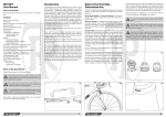
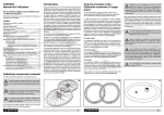
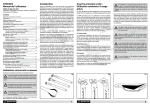
SYNCROS
User Manual
Handlebars, stem, headset
Important information about use, care, maintenance and installation
Contents
Notes on This User Manual...........................................................................1
Introduction.......................................................................................................1
Before Your First Ride – Intended Use.......................................................2
Before Every Ride..............................................................................................3
Special Characteristics of Carbon...............................................................3
Cleaning and Care............................................................................................4
Maintenance......................................................................................................4
General Notes on Installation......................................................................5
Carbon assembly paste.........................................................................5
Using a torque wrench..........................................................................6
Headset................................................................................................................7
Checking the headset............................................................................7
Adjusting the Aheadset®-headset.....................................................7
Headset maintenance............................................................................9
What to Bear in Mind with Carbon Steerer Forks.................................9
What to Bear in Mind with Integrated and
Semi-Integrated Headsets.........................................................................10
Installing the Bearing Cups of Conventional
Aheadset®-Headsets and Semi-Integrated
Aheadset®-Headsets into the Frame.......................................................10
Installing Aheadset®-Stems.......................................................................11
Special Characteristics of SYNCROS FRIC Stems................................11
Installing the LO-Ball Direct Mount Stem.............................................12
Installing the Handlebars...........................................................................13
Adjusting the Shifters and Brake Levers ..............................................13
Installing Bar Ends . ......................................................................................13
Adjusting Handlebar Height and Fore-to-Aft Position.................... 14
Aheadset®-Stems – Height Adjustment with Spacers .................... 14
Installing the Grips . .....................................................................................15
Warranty Terms .............................................................................................15
Additional manufacturer’s warranty ............................................16
A note on wear .....................................................................................16
Introduction
Congratulations, when buying a SYNCROS component, you made
a superb choice. SYNCROS develops, tests and manufactures our
products with dedication to uphold the highest standards of quality. Like all high-quality sports equipment, SYNCROS components
require careful installation in order to function properly and provide long-term dependability. We recommend that you ask a qualified mechanic at your authorized SYNCROS dealer for help with
installation and use SYNCROS components together whenever
possible in order to achieve optimum performance and durability.
Our precise tolerances are intended to ensure component compatibility, and are carefully monitored during production and quality
control so that installation will be easy and trouble-free.
This manual contains important notes about use, care, maintenance and installation.
Please read this manual carefully, beginning with the general
information, followed by the chapter referring to the component
you purchased, or you intend to use. Doing so will ensure smooth
installation and trouble-free use of the product.
Keep this user manual for your records and future reference. If
you sell or lend your component or bike to someone, share this
manual with the new user.
With SYNCROS components, as with all lightweight bicycle products, special care and attention need to be paid to proper installation and intended use. Materials used by SYNCROS are extremely
strong and durable, with very low weight. However, sometimes
they can break, rather than bend, in the event of an accident.
Internal damage to the component may not show up obviously or
with visible signs of damage. In the event of undue stress of any
kind, e.g. as a result of a crash, the components may fail and thus
lead to an accident with unforeseeable consequences need to be
inspected by a qualified mechanic to ensure the product is safe to
continue using. Therefore consult your SYNCROS dealer after any
such occurrence.
Before Your First Ride –
Intended Use
SYNCROS handlebars (a), stems (b) and headsets (c) are designed
for mountain bikes and their typical use.
Mountain bikes are designed to be used for off-road cycling
and for riding over natural terrain (e.g. terrain of a mountain bike
marathon and cross country racing). Due to their design and
equipment these bikes are, however, not intended to be used on
public roads. If you intend to use this type of bicycle on public
roads, it must be fitted with the devices and equipment prescribed for this purpose. Standard cross country, marathon and
all-mountain bikes are not suitable for freeriding, dual slalom,
downhill riding, jumps or the like. There are special mountain bike
types for these specific forms of cycling. SYNCROS components
are divided according to their intended use:
Never make any changes to seat post or saddle. Do not
file or drill holes in components, especially in carbon
components, as it will compromise their structural integrity
and void your warranty.
We recommend that you always use SYNCROS components together in order to achieve optimum performance and component
durability. If you intend to combine SYNCROS components with
components from other manufacturers, make sure they are compatible, i.e. that all dimensions are identical with the specifications
given in this manual.
SYNCROS handlebars, stems and headsets are designed
for an overall load of 110 kilos (242 lbs) including rider
and baggage, e.g. rucksack.
FL (Feather Light)
The SYNCROS components of the FL series are designed for an
easy off-road use and are usually built on cross country, marathon
and touring mountain bikes. The FL components are not suitable
for use in rough terrain, jumps or drops.
a crash, such as an accident or other major
! After
impact, have your handlebars, stem, headset and bar
ends by a SYNCROS dealer, if necessary for your own
safety.
AM (All Mountain)
The SYNCROS components of the AM series are designed for a
moderate off-road use. and are usually built on Enduro and all
mountain bikes. The AM components are not suitable for dual,
dirt, downhill or freeride use.
FR (Freeride)
The SYNCROS components of the FR series are designed for a
hard off-road use on secured terrain and thus for extreme stress,
competitive use included. They are usually built on dirt, fourcross,
urban and dual slalom bikes.
your handlebars, stem, headset and bar ends, if
! Ifmounted,
produce any creaking or cracking noises or
show any external sign of damage, such as notches, cracks,
dents, discolourations etc., do not use your bike any longer.
Ask your SYNCROS dealer to check these components
thoroughly and to replace them, if necessary.
i
If you have any questions, please contact your
SYNCROS dealer.
For more information see the specifications in our catalogue and/
or visit us at www.syncros.com.
Notes on This User Manual
Pay particular attention to the following symbols:
(a)
(b)
(c)
This symbol means that your life or health may be in
danger unless you comply with provided instructions or
carry out prescribed measures.
!
This symbol warns you about actions that could lead to
damage of property or the environment.
i
This symbol indicates there is special information on how
to handle the product and may refer you to a specific
passage in this manual requiring your special attention.
The possible consequences described above are not repeated
every time one of the symbols appears!
1
2
Before Every Ride
Special Characteristics of Carbon
Check the following points before setting off:
All SYNCROS products made of carbon fiber-reinforced resin, also
referred to as carbon or abbreviated CFR (c), require special care
and attention.
1. Verify that the headset is free of play and moves easily (a). Make a
visual inspection!
2. Check the tight fit of the stem on the fork steerer and of the
handlebars in the stem.
3. Are the quick-release levers or nuts of the front and rear wheel
properly closed (b)? For more information see the respective
chapters of your general bike user manual.
Improperly closed quick-releases or thru axles can cause
the wheels to come loose. This can lead to a serious
accident!
i
Read the user manual of your bicycle manufacturer
before you set off!
Carbon is an extremely strong material which combines high
compression resistance with low weight. Please note that carbon,
unlike metals, shows no visible deformation after overstress, even
though some of its fibers may be damaged. This makes it very
dangerous to continue using a carbon component after an impact
or undue stress, as it may fail without previous warning thereby
causing an accident with unforeseeable consequences.
If your SYNCROS carbon component sustained this kind of impact
or undue stress, we strongly recommend that you take your complete bike to your SYNCROS dealer for inspection. He will check
the damaged bike and, if necessary, replace the deficient component. In case there are any unanswered questions or doubts, the
dealer can contact SYNCROS or one of our SYNCROS distributors
directly.
For safety reasons components made of carbon must
never be repaired; they must be replaced at once. Make
absolutely sure that any damaged component is never re-used;
it should be destroyed to ensure that re-use is impossible.
(a)
Parts made from carbon should never be subjected to excessive
heat under any circumstances. Therefore, never have a carbon
component enamelled or powder-coated. The temperatures
required for doing so could destroy it. Do not leave carbon components near a source of heat or in a car or trunk during hot or
sunny weather.
Components made of carbon have, like all lightweight bicycle
parts, only a limited service life. Therefore, to be on the safe side
it is recommended that you replace handlebars, stems and headsets depending on use at regular intervals (e.g. every three years),
even if they were not involved in an accident or similar incident.
Make sure the clamping areas are absolutely free of grease and
other lubricants, especially when the clamping surfaces are made
of carbon! Grease will penetrate the surface of the carbon component and undermine the stability of joined parts by reducing
the coefficient of friction. Greased carbon components may never
again provide a safe clamping surface! When you install carbon
(b)
(c)
components, apply carbon assembly paste (e.g. from RITCHEY) to
interconnecting surfaces to increase friction. This will allow you to
tighten bolts to prescribed torque limits, execute proper installation and attain reliable, slip-free hold.
If any notches, tears, deformations, dents or dis
colorations etc. are visible on your carbon component,
or if it makes creaking or cracking noises, do not use the bike
until the component has been replaced. After undue
stress, a crash or other major impact, replace the component or
have it inspected by your SYNCROS dealer before using it
again.
!
Do not store carbon components in the blazing sun or
near a source of heat.
Cleaning and Care
Clean your handlebars, stem and headset with water and a soft
cloth at regular intervals. If necessary, use a non abrasive soap to
remove grime. You may add a little detergent liquid for cleaning
and removing tough stains, such as oil or grease, from hard surfaces. Do not use degreasing agents, which contain organic solvents (e.g. acetone, trichloroethylene, methylene, etc.). Chemicals
of this sort may damage the finish or substructure of the material.
Maintenance
Check the tightening torque of all bolts after the first 100 to
300 km (60 to 180 miles) or 5 to 15 hours of use. Tighten them, if
necessary, with a torque wrench to the prescribed torque setting.
Check at least every 1,500 kilometres (930 miles) or 75 hours of
use thereafter (e). Please note that adjusting bearings are jobs
best left to skilled mechanics. Ask your SYNCROS dealer to do
these routines.
Loose or overly tightened bolts may result in an
accident!
After about three years the handlebars, stem and headset have
aged to an extent that they need to be checked thoroughly and
have to be replaced, if necessary. Ask your SYNCROS dealer for
advice.
Although headsets have seals, they are not entirely tight. Therefore, have the headset dismounted and re-lubricated by an authorized SYNCROS dealer at least once a year, depending on the
intensity of use.
After your bike has dried, apply a wax based polish (d) to painted,
carbon and metal surfaces (exception: braking surfaces). Polish
the components after the wax has dried. With this treatment your
handlebars, stem and headset will keep their nice appearance for
years.
While cleaning your bike, look for cracks, scratches,
dents or changes to the colour. In case of any doubt,
contact your SYNCROS dealer. Have damaged or defective
components replaced immediately.
Make absolutely sure to keep the braking surfaces or
rotors free of cleaning agent, grease or oil. Otherwise
the braking performance might be drastically reduced or
even rendered ineffective.
(d)
(e)
carbon
3
4
General Notes on Installation
Carbon assembly paste
In general, handlebars, stem and headset installation are jobs for
skilled mechanics. We therefore recommend that you have these
jobs performed by an authorized SYNCROS dealer. Each of the
following instructions must be followed strictly. Non-observance
of these instructions can lead to component failure, resulting in a
crash or injuries.
Installing components with carbon assembly paste
!
Installing non-matching components can result in bolt
failure and consequently in a serious accident.
We recommend that you always use SYNCROS handlebars, stems
and headsets together, as they are designed to fit and function
as an integrated whole. If you decide to use a component from
another manufacturer, consult the user manual of this component
regarding size accuracy to ensure proper fit and usability with
SYNCROS components.
SYNCROS assumes no responsibility for problems resulting from
a SYNCROS component being used with a component from another manufacturer.
Before installation watch out for sharp edges and burrs on all
clamping surfaces of the handlebars, stem (a) and headset. Do
not use these components, if they have burrs or sharp edges. If
there are burrs or sharp edges on a SYNCROS or non-SYNCROS
component, have your SYNCROS dealer inspect it to see, whether
it is usable or whether the issue can be remedied and how.
Instructions for use
Carbon fiber components are particularly vulnerable to damage
caused by excessive clamping force. Carbon assembly paste (e.g.
from RITCHEY (b) creates extra friction between two surfaces,
allowing the tightening torque to be reduced by up to 30%.
This is especially useful in the clamping areas of seat post and seat
tube, i.e. an area where too much clamping force can damage
either component, causing component failure or voiding the
warranty. By reducing the clamping force, carbon assembly paste
relieves stress on sensitive carbon surfaces, preventing damage
to fibers or the cracking of the clamping areas. It also retains its
effectiveness in wet conditions and provides maximum protection against corrosion.
Carbon assembly paste can be used for all carbon, aluminium and
steel connections including:
• Stem/steerer tube clamping areas (c)
• Seat post/frame clamping areas
• Stem/handlebars clamping areas (d)
Carbon assembly paste (e.g. from RITCHEY) is always ideal for
clamping, as it does not harden.
Using a torque wrench
Before applying carbon assembly paste, remove dirt particles and
lubricant residues from the surfaces to be treated. Then, apply a
thin and even film of carbon assembly paste to the cleaned surfaces using a brush, lint-free rag or chamois/artificial chamois.
Install the component, as prescribed by the manufacturer. Use
a torque wrench and do not exceed the prescribed maximum
tightening torque. Remove any excess carbon assembly paste and
close the container after use.
Additional information
Many manufacturer warranties do not cover damage to components due to overtightening. Always observe the maximum
tightening torques prescribed by the manufacturers for each
component.
To achieve long lasting and problem-free clamping of components, SYNCROS considers the use of a torque wrench absolutely
necessary (e). If the prescribed tightening torque does not create
sufficient clamping force, apply carbon assembly paste (e.g. from
RITCHEY), to interconnecting surfaces to increase friction.
Exceeding the maximum tightening torque on clamp bolts of
SYNCROS components creates a too high clamping force, which
can lead to component failure. This not only bears a high risk of
accident, but also voids the warranty.
Loose or overly tight bolts can result in component
failure and in an accident. Strictly observe the tightening torque specifications. If you do not have a high-quality
torque wrench, contact your SYNCROS dealer.
Use a torque wrench to verify you are within the prescribed torque
limits. Using carbon assembly paste will allow you to safely install
your bicycle components – particularly in the case of carbon fiber
components – without exceeding the tightening torques prescribed by the manufacturers. In most cases, using carbon assembly
paste will enable you to use a tightening torque reduced by 30%
to install your components.
i
Carbon assembly paste (e.g. from RITCHEY) is neutral to
copper and aluminium alloys, steel and synthetic
materials, and will not damage product surfaces.
(d)
(c)
(e)
If you fit a headset to an existing fork, check the steerer tube and
the old headset carefully for scratches, abrasion marks and notches after removing them. Notches in the contact area indicate
defective processing or deficient design of the headset in these
areas.
Do not use components, if you are not absolutely
sure about their compatibility. In case of any doubt
ask your SYNCROS dealer for advice.
Do not use further damaged components! If there is
any doubt, we recommend that you replace the
component. Do not use your bike until this has been
done.
(a)
(b)
5
6
Headset
Checking the headset
The headset connects the fork to the frame, but allows it to move
freely. It must turn with virtually no resistance, if the bicycle is to
run straight, stabilising itself as it travels. Shocks caused by uneven
road surfaces expose the headset to considerable levels of stress.
As a result of this it can become loose and go out of correct adjustment. You should check the headset at regular intervals, readjust
it, if necessary, and have it greased at least once a year. Noises, in
particular cracking noises, are often due to a lack of lubrication.
Pull the front brake lever and place the fingers of your other hand
around the upper headset cup (b).
If you have a fork with steel/aluminium steerer tube, you can apply
mounting grease on the steerer tube in the area of the headset
and the spacers, however, not in the area of the stem clamping.
If you have a fork with carbon fiber steerer tube, you must not
apply mounting grease! The surface between steerer tube and
stem as well as between the pre-load mechanism (clamping cone)
and the inner side of the steerer tube must remain free of grease,
otherwise a reliable clamping of these components cannot be
granted. If you have a carbon fork, the grease must, therefore, be
applied carefully and systematically between the steel/aluminium
parts of the bearing, the clamping or between the contact areas
of the aluminium spacers.
Recurring bearing play may be due to insufficient friction between stem and fork and/or to a poor fit of the counter bearing in
form of a cone mechanism in the fork steerer. Apply a thin layer
of carbon assembly paste on the clamping surfaces to ensure a
proper and gentle clamping.
Furthermore, check whether the fork steerer ends 2 to 3 mm
below the top of the stem (a) or spacer, if one is installed on top,
otherwise adjusting the bearing play will be impossible.
Bring your weight to bear on the saddle and push the bicycle a
little back and forth. If there is movement at the gap, the headset
shows too much play. Repeat this test with the front wheel turned
crossways.
Letting the front wheel bounce to the ground from a height of
approx. 10 cm is another method that requires, however, a certain
amount of experience. Knocking noises indicate too much bearing play. However, rattling brake levers, cables or cycle computers may be misguiding!
To check whether the headset turns smoothly, take hold of the
top tube and lift the front part of the bicycle until the front wheel
is about 20 cm above the ground. With a little tap on the grips,
the handlebars should turn easily until the front wheel is at least
at right angle to the direction of motion. Perfom this test to the
right and to the left.
If the handlebars do not turn or only half way, slacken the cables
and try again. In case there is any cracking or rubbing noise, check
where it comes from. Often these noises are due to cables that
are dry or even rusty in their cable stops. In this case, please apply
thin lubricant.
If that still does not help, check whether the fork turns freely at
the bottom of the head tube and whether the bearing cover has
enough play. The gaps as well as the seals must be even. To check
the headset turn the fork from far left to far right.
Adjusting the Aheadset®-headset
Steering resistance or play in some handlebar positions
can be due to improper fit, i.e. when the bearing races
in the frame are not snug as a result of deficient processing or
when unsuitable bearings were mounted. In such an event,
please contact your SYNCROS dealer.
Headsets come in different diameters and angles. Often
i the exact headset description is printed directly on the
cartridge bearing. If not, a headset gauge that you can obtain
from your SYNCROS dealer will help you.
(a)
Check the headset as described in chapter “Checking the headset”. In case there is bearing play, tighten the adjusting bolt by
another quarter or half a turn. Do not over-tighten the headset;
otherwise there is the risk of headset failure.
!
Do not over-tighten the top Allen bolt, it is intended for
adjustment! Tighten the bolt carefully in quarter-turns
and check the play regularly.
Once the play is properly adjusted, bring the stem in alignment
with the front wheel. Check the alignment from the top. The handlebars should be at right angle to the direction of motion.
Check the tight clamping of the stem by holding the
front wheel between your knees and trying to turn the
handlebars relative to the front wheel. A loose stem can lead to
an accident!
If the stem cannot be tightened on the fork steerer
tube with a tightening torque of 5 Nm, in spite of
carbon assembly paste on the clamping surfaces, stem and fork
are incompatible. Replace the stem by a matching model or ask
your SYNCROS dealer for assistance.
Tighten both clamping bolts alternately by using a torque wrench
(d). If you use a standard torque wrench, start with a minimum
tightening torque of 4 Nm. In case the stem clamping is not tight
enough, increase the tightening torque to 5 Nm (e).
After adjusting the headset check the tight clamping of the stem
by holding the front wheel between your knees and trying to turn
the handlebars relative to the front wheel. In case the stem is not
tight, do not tighten the bolts any further. Use carbon assembly
paste instead to increase friction in the clamping areas.
i
Observe the specific instructions for the LO-Ball Direct
Mount Stem in chapter “Installing the LO-Ball Direct
Mount Stem”.
i
Please also observe the specific instructions regarding
installing for the FRIC Stem in chapter“Special Characteristics of SYNCROS FRIC Stems”.
Check the tight clamping once again. If the stem is still not tight,
fork and stem are probably incompatible. Replace the stem by a
matching model or ask your SYNCROS dealer for assistance.
With carbon steerer tubes, make sure the inside of the
tube is supported by an expander-cone mechanism (for
adjusting the headset). Strictly observe the instructions about
stem tightening in the user manual of the fork manufacturer.
(d)
Adjusting the headset is a job for a skilled mechanic.
i Have this work done by an authorized SYNCROS dealer.
If you intend to do the adjustment on your own, please note that
you need special tools, e.g a torque wrench with bits.
Release the clamping bolts on the stem side by two to three turns
without unscrewing them entirely.
The Allen bolt located in the top cap is intended to re-adjust
the bearing play (c). Turning the bolt clockwise removes play, as
the stem is pressed downward on the bearing; turning the bolt
anticlockwise increases the play.
(b)
(c)
(e)
2 mm
7
8
Headset maintenance
The maintenance of the headset, the removal of noises in spite of
correct adjustment or an insufficient steering behaviour require a
dismounting of the fork from the frame.
maintenance of the headset is a job for a skilled
! The
mechanic. Have this work done by an authorized
SYNCROS dealer. If you want to try it on your own, you should
have the know-how and experience of a mechanic as well
as special tools, if necessary.
Undo the front brake and remove the front wheel.
Unscrew the upper Allen bolt completely and remove the top cap.
Release the bolt(s) on the stem side.
Pull off the handlebars including stem, keep hold of the fork with
one hand and let the handlebars/stem hang down. Make sure
frame, levers, handelbars and stem remain undamaged.
Verify that the top clamping area of carbon steerer tubes
is free of grease!
Observe the correct order of assembly and place the lower bearing on the crown race. The bevel of the cartridge bearing’s outer
ring, normally, shows in direction of the head tube, whereas the
bevel of the cartridge bearing’s inner ring shows to the crown
race. Slide the fork from below into the head tube of the frame.
Slide the upper bearing that is greased on the outside, the upper
bearing cone, the bearing cover and the spacers completely on
the steerer tube until the fork is mounted almost free of play. Make
sure the clamping area of the stem is absolutely free of grease and
apply carbon assembly paste. Slide the stem on the steerer tube
and install the top cap. Adjust the headset as described in chapter
“Adjusting the Aheadset®-headset”.
Remove the spacers (a), the bearing cover and the upper bearing
cone. Clean the components with a rag and arrange them in the
order you removed them. Keep the order in mind.
What to Bear in Mind with Carbon
Steerer Forks
Carefully pull out the fork and wipe off any dirt from the components (b). Check on the dismounted fork, whether the crown
race was installed horizontally, whether it is in sound condition
(i.e. without notches), and whether the steering tube is free of
scratches, notches, colour changes etc. over its entire length and
circumference.
Carbon steerer tubes must remain free of grease, otherwise a reliable and sufficient clamping of the stem will not be achieved. You
would require high tightening torques damaging the steerer tube
or the stem and resulting in a failure. Degrease the stem and the
fork with benzine or spirit, if necessary. Apply carbon assembly
paste subsequently (d)!
Remove the bearings, wipe off the grease from the bearing cup
races.
Pre-load mechanisms acting as counter bearing for the adjusting
bolt inside the fork steerer are often delivered without being greased. In this case increased inner friction prevents the transformation of bolt force into clamping force. Apply grease specifically on
the inner, bevelled surfaces of the slotted sleeve and the inner
cone.
Check whether the bearings turn freely and without play and
make sure they are free of chips etc.
If you have an open bearing headset, you should check in addition, whether the bearings are well greased. Make sure there are
no chafe marks or notches.
Asymmetrical marks of that kind indicate a careless processing of
the frame.
Apply plenty of grease (not carbon assemply paste) on the bearing and bearing races during reassembly that will seal the bearings in addition (c). Wipe off excess grease after reassembly.
(a)
The outer surface of the sleeve must remain free of grease. Apply
carbon assembly paste in this area, as well, bevor tightening the
mechanism in the fork steerer.
What to Bear in Mind with
Integrated and Semi-Integrated
Headsets
With integrated headsets the upper and lower bearing cup races
are part of the head tube, with semi-integrated headsets they are
normally pressed in by the manufacturers. This allows smooth
transitions between headset, fork and stem.
The fork crown race is normally provided with a slit that allows an
easy installation on the fork steerer.
!
Apply grease on the entire headset including bearing
cup races to ensure smooth running and to prevent
corrosion!
Verify that the gaps between bearing cover and head tube as well
as between fork crown and lower bearing cup race are evenly
parallel. If they are not, the bearings possibly run rough and wear
down fast.
Installing the Bearing Cups
of Conventional Aheadset®Headsets and Semi-Integrated
Aheadset®-Headsets into the
Frame
Place the crown race horizontally onto the fork crown. Slide the
crown race onto the steerer either manually or with an appropriate special tool. With the desired minor undersize of the crown
race towards the fork crown you need to tap slightly on the crown
race to bring it into the correct position without leaving any gap
between crown race and fork crown. Keep the fork in hand during
hitting and do not put it down. Risk of breakage!
Before installation thoroughly check the cleaned fork
steerer, in particular the fork crown and the stem
clamping area, for damage, such as cracks.
Perform the installation only with headset tools. An appropriate press fit of the bearing cup races into the frame can only be
achieved with these tools. Precondition is, however, that the tolerances are observed and that the surfaces gliding on top of one
another are well greased. Verify not to slide on the bearing cup
races in oblique position and make sure they are flush. Tighten
the special tool evenly and observe as the bearing cup races slide
into the head tube.
Bearing cup races that you can slide in manually will cause cracking or rattling noises during cycling. Degrease the bearing cup
races and the inner face of the headset in a metal frame and apply
some two-component adhesive, according to the manufacturer’s
instructions. If you have a carbon fiber frame, use carbon assembly paste (e.g. from RITCHEY)!
Let the adhesive harden before re-installing the fork.
The installation of the Aheadset®-headset is a job for a
skilled mechanic. Have this work done by an authorized
SYNCROS dealer. If you want to perform this task yourself, you
should have the know-how and experience of a mechanic as
well as special tools, if necessary.
Never use a star nut as counter bearing inside the fork
steerer! Risk of breakage!
(b)
9
(c)
(d)
10
Installing Aheadset®-Stems
The SYNCROS FL and AM stems can be installed in either vertical
orientation. These flip-flop models allow handlebars installation
at two different heights by simply inverting the stem.
Verify that the stem and fork steerer tube always have matching or
compatible clamp diameters!
If you fit a new stem on a fork with carbon steerer tube, check the
clamping area for notches or abrasion marks. In case such damage
is actually visible, ask your SYNCROS dealer whether it is necessary
to have the fork replaced.
Make sure the clamping areas are absolutely free of grease, especially when the clamping surfaces are made of carbon.
Apply carbon assembly paste (e.g. from RITCHEY) to optimise the
clamping. Grease the threads and the connecting surfaces/heads
of the steerer clamp bolts. Keep lubricants away from clamping
surfaces.
Slide the stem onto the fork steerer tube. It must fit snugly onto
the fork. Do not fit stems which have play on the steerer tube.
Depending on the steerer tube length and the desired stem position, install spacers on the fork steerer above the upper cover of
the headset and / or above the stem. You can stack them up to a
maximum height of 30 mm.
These spacers are available in different heights. You have installed
the correct number of spacers, when the steerer tube ends 2 mm
below the top edge of the stem or spacer, if one is installed above
the stem.
Verify that the stem provides sufficient support for the steerer
tube and that the steerer tube ends 2 mm at the most below
the top edge of the stem. This ensures a reliably clamping when
tightening the clamping bolts of the steerer tube clamp to the the
prescribed tightening torque.
If your preferred stem height results in a deeper position of the
stem on the steerer tube, the steerer tube projects from the stem.
To check the correct position, insert spacers at an appropriate
height on top of the steerer tube. After the test ride the steerer
tube of a carbon fork must be shortened.
(a)
The space between the top of the steerer tube and the
upper edge of the stem should not exceed 3 mm.
Tighten the stem bolts only a little, if you intend to install
the handlebar right afterwards. Finish by adjusting the headset.
!
clamp bolts of SYNCROS stems are designed to
! The
oppose each other for proper load distribution during
clamping. Please check that the bolt heads are always
oriented in opposition to each other.
Screw in the greased bolts of the handlebar clamp brackets with
your fingers by a few turns. Tighten the two lower bolts until the
clamp slots of both brackets measure approx. one millimetre (b).
Subsequently, the stem must be installed on the fork steerer tube.
Slide the stem onto the fork steerer tube.
Mount the the handlebar fittings and the grips on the handlebars.
Tighten them only a little, as they will be fixed in the correct position at a later date.
Adjust the headset as described in chapter “Adjusting the Headset”. Bring the stem in alignment and tighten the two bolts of the
steerer tube clamp with your fingers.
Tighten the two bolts evenly, i.e. alternately and in small increments, by using a torque wrench to the minimum limit of the
recommended tightening torque of 5–6 Nm (c).
Special Characteristics of
SYNCROS FRIC Stems (a)
The instructions given for our standard product range, in general,
also apply to the SYNCROS FRIC stem. The following instructions
about the special characteristics should be regarded as supplementary!
Installing the Stem to the Handlebars and the
Steerer Tube
Before proceeding with installation, be sure the stem and the
handlebars have the proper and matching clamping diameter.
The FRIC stem is only permitted with handlebars with a 31.8
mm clamping diameter. We strongly recommend that you use
SYNCROS handlebars.
Position the handlebars in a way that they extent the same
distance from the stem on either side by offering you a comfortable grip position.
Tighten the two upper bolts of the handlebar clamp brackets
evenly, i.e. alternately and in small increments, by using a torque
wrenceh to the minimum limit of the recommended tightening
torque of 4–5 Nm (d).
(c)
Adjusting the Headset
With a SYNCROS folder stem adjusting the headset requires different procedures as with other SYNCOR stems. You need to release
the clamp bolts of the steerer tube as well as the clamp bolts of
the handlebars by two to three turns at the most.
After adjusting the headset tighten first the clamp bolts of the
steerer tube to the required tightening torque of 5 to 6 Nm.
Bring the handlebars then in the correct position and tighten the
two upper bolts of the handlebar clamp brackets according to the
recommended tightening torque of 4–5 Nm.
Finally, check the reliable fit of the handlebars in the
stem and of the stem on the steerer tube.
The SYNCROS LO-Ball Direct Mount stem (e) is only compatible
with the double crown suspension forks FOX 40 and Rock Shox
Boxxer (from model year 2009).
Release the two bolts of the steerer tube clamp and the bolts
of the handlebar clamp brackets by two to three turns without
unscrewing them entirely.
The LO-Ball Direct Mount stem is screwed with 4 bolts directly to
the upper fork crown. The handlebars are installed, as described
in chapter “Installing the Handlebars” by observing the prescribed tightening torque of 6 Nm.
To install the handlebars you need not dismount the two front
clamp brackets completely. Slide in the handlebars without fittings from the side into the stem. If you have riser bars, turn the
handlebars a little in both directions along the longitudinal axle
to slide the bends easier through the handlebar clamp brackets.
Do not use brute force, otherwise you will scratch the handlebars.
Risk of breakage! Ask your SYNCROS dealer for advice instead.
11
Observe the recommended maximum tightening
torques. Always use a torque wrench and observe
the torque settings indicated on the component in case of
doubt.
Installing the LO-BALL Direct
Mount Stem
The SYNCROS FRIC stem has a symmetrical design and can therefore be installed in either vertical orientation. We recommend,
however, that you install the stem in a way that the SYNCROS lettering is not upside down.
(b)
Bring the handlebars, the fittings and the grips in the correct
position and tighten them with a torque wrench according to the
instructions of the manufacturers. Finally, check the reliable fit of
the handlebars in the stem, of the fitting on the handlebars and of
the stem on the steerer tube.
(d)
i
Read the user manual of your fork manufacturer before
installing a LO-Ball Direct Mount stem.
(e)
12
Installing the Handlebars
Before you start installation verify that the stem you have chosen
has a clamping diameter matching the handlebars!
Stems with a 31.8 mm clamping are for example only compatible
with handlebars with a clamping diameter of 31.8 mm.
Position the stem clamp in the middle of your new SYNCROS
handlebars so that the handlebars extend the same distance from
the stem on each side. If the handlebars do not slide easily into the
stem clamp or if there is play between the two components, ask
your SYNCROS dealer whether both components are compatible.
Mountain bike handlebars are normally mounted with the sweep
supporting a natural ergonomic hand position, i.e. pointing
slightly rearward. The handlebar position is correct when your
wrists are relaxed and your elbows not flared out too much.
Tighten the greased bolts of the stem faceplate with your fingers
by a few turns. Gently tighten all four bolts with a quality torque
wrench (a) until they are snug and verify that the upper and lower
clamping slots are identical in width. Do not exceed the prescribed tightening torque.
Tighten the fixing bolts evenly in a cross pattern, i.e. alternately
and in small increments to the minimum limit of the recommended tightening torque.
The recommended maximum tightening torque for SYNCROS
4-bolt stems is 4 to 6 Nm (depending on model). Always use a
torque wrench and observe the torque settings indicated on the
component in case of doubt.
Check shifter and brake lever clamps for burrs and sharp edges.
Do not use shifters or brake levers with burrs or sharp edges to
prevent your handlebars from damage and dents. Components
that are affected by burrs and sharp edges should be checked by a
SYNCROS dealer. They will see, whether this is a problem that can
be solved or whether the component has to be replaced. Loosen
clamping bolts completely to ensure clamps are open all the way
before sliding the shifters and brake levers onto the handlebars.
Start tightening the clamping bolts slightly, so that the levers can
still rotate freely. Bring the levers to the desired position. Tighten
the bolts to the prescribed tightening torque to ensure a reliable
hold (b).
Never rotate the levers on handlebars after you have tightened
the clamping bolts. Otherwise you will scratch the surface and
mar the finish. In addition you run the risk of damaging the material.
(a)
!
Read through the manufacturer`s user manuals of all
components before you follow the above instructions.
Never shorten carbon fiber mountain bike handlebars ‚
by cutting off the ends, as handlebars are generally
reinforced where shifters and brake levers are installed.
Shortening handlebars by cutting off the ends can damage
the handlebars and result in an accident during use! Any
modification to a SYNCROS carbon component will void the
warranty.
Adjusting the Shifters and Brake
Levers
Turn the loosened grips on the handlebars so that they show
slightly downward. Sit on the saddle and place your hands on the
grips with your fingers on the brake levers. The back of your hands
should form a straight line with your forearms. Adjust the shifters
to the correct anatomical position.
In case both the shifters and the brake levers are still not tight,
verify that each bolt has been tightened to the recommended
torque (5 Nm for SYNCROS). If each bolt has been tightened to a
tightening torque of 5 Nm and the clamping force is still insufficient, release the bolts, remove shifters and brake levers and apply
carbon assembly paste to the clamping areas. Retighten each bolt
individually to a tightening torque of 5 Nm. If the shifters and
brake levers are still not tight on the handlebars, seek the assistance of your SYNCROS dealer.
Installing Bar Ends
Bar ends add more hand positions to your handlebar configuration. They are usually set to a position that provides more leverage
and more comfort when you pedal out of the saddle.
High-quality bar ends are suitable for all SYNCROS handlebars.
Verify that the clamping areas of the bar ends are free of burrs
and sharp edges. Do not use bar ends with burrs or sharp edges.
Burrs are sharp and can cut into other components. If there are
any burrs or sharp edges, contact your SYNCROS dealer.
Loosen the shifter and brake lever bolts and move the levers
toward the stem to ensure the bar ends have sufficient clamping
space. If the grips have end caps, cut them so you can move the
grips toward the stem, as well. Do not use any liquids or grease to
loosen the grips; if necessary, use compressed air to loosen them.
Loosen the bar end bolts on the bottom side of the bar ends by
two to three complete turns.
Slide the bar ends on the respective side of the handlebars (c).
Angle the bar ends according to personal preference and make
sure they are both at the same angle. Observe possible right/left
references on the bar ends.
Retighten the bolts carefully in small increments of 0.5 Nm. Do
not exceed the maximum torque of 5 Nm for the bolts of bar ends
used with SYNCROS handlebars. Never exceed the maximum
torque indicated on the components (d).
tight fit of the bar ends on the handlebars cannot
! Ifbea achieved
in spite of using carbon assembly paste
on the contact surfaces, bars ends and handlebars are not
compatible. Replace the bar ends or the handlebars by appropriate models.
!
The interfacing clamping areas of stems, handlebars,
bar ends, shifters and brake levers must be tightened
to specified torque settings.
Installing bar ends to unsuitable handlebars can lead
to sudden failure during use and therefore result in
an accident. Bar ends with asymmetric clamp styles and sharp
edges are mostly unsuitable for use with handlebars. To be
on the safe side, ask your SYNCROS dealer for advice.
Mounting bar ends to unsuitable handlebars, i.e.
handlebars with thin wall thicknesses that are not
designed to withstand the specific load, can lead to handlebar
failure during use and result in an accident!
(b)
13
(c)
Adjusting Handlebar Height and
Fore-to-Aft Position
Both the handlebar height and the stem length determine how
much your upper body will be inclined forward. Lowering the
handlebars gives the rider a streamlined position and brings
more weight to bear on the front wheel. An excessively low handlebar position may prove less comfortable, especially on longer
rides, and can strain wrists, arms, upper body and neck. Seek the
assistance of a qualified bike fit expert, especially if you experience pain or discomfort after set up and use. If necessary, your
SYNCROS dealer will help you find a seating position according
to your needs.
Aheadset®-Stems –
Height Adjustment with Spacers
On bikes using a threadless headset system, or Aheadset®-system
((a), p.15) the stem is an integral part of the headset. To find the
appropriate height the stem must be dismounted and re-mounted. If you change the position of the stem, you must also readjust
the headset (see chapter “Adjusting the Headset“). The vertical
position of the stem is determined by the arrangement of the
spacers. In the case of flip-flop models it is also possible to reverse
the stem in order to achieve a higher or lower handlebar position.
Loosen the headset cap bolt at the top of the fork’s steerer tube.
This cap serves to adjust the initial bearing pressure. Remove the
cap and loosen the stem’s steerer clamp bolts, then pull the stem
up and off the steerer tube. Now you can remove the spacers.
Reposition the spacers on the steerer tube above and below the
stem in order to position the handlebar at the desired height.
Observe the maximum stacking height of spacers of
30 mm below the stem.
Check the reliable fit of all components, as described above.
If you want to reduce the number of spacers, you have
i
to shorten the steerer tube. This shortening is irreversible. Cutting the steerer tube is a job for a skilled mechanic.
Have this work performed only after you have found the ideal
position. Instead of shortening the steerer tube you have also
the option to modify the arrangement of the spacers. Make a
test ride and place the equal number of spacers you have removed from below the stem above the stem and vice versa.
(d)
14
Installing the Grips
Warranty Terms
Additional manufacturer’s warranty
A note on wear
For a reliable fit without play SYNCROS grips must be mounted on
handlebars that are free of oil and grease.
Under European consumer law the purchaser has full statutory
warranty rights for two years from the delivery of the SYNCROS
product. Your dealer is liable for any lack of conformity with the
contract, namely that your purchased product is free of faults,
which are impairing its worth or its typical use. In case of a lack of
conformity you may require the dealer to repair the product or to
replace it, unless this is impossible or disproportionate. Otherwise
you may require an appropriate reduction of the price or have the
contract rescinded, the latter being excluded if the lack of conformity is minor.
SYNCROS products have been developed and manufactured with
great care and have been subject to quality assurance and control
tests to help ensure that your SYNCROS product performs as it is
meant to. Our products are examined and tested both internally
and by external neutral test laboratories on an ongoing basis.
Components on bicycles are subject to wear due to their function. The rate of wear will depend on care and maintenance, the
bike‘s usage and the environment it is exposed to such as rain,
mud, dust, and sand. Some components require regular care and
maintenance, but despite the best maintenance program, all
components will eventually reach the end of their serviceable life,
depending on conditions and intensity of use.
SYNCROS locking grips (with 2 or 4 bolts) can be mounted easily
by sliding onto the handlebars. Verify that the clamping mechanism is at the end of the handlebars. Slide the grip into the correct
position on the handlebars and tighten the bolts to ensure a tight
fit of the grip (b). Never exceed the maximum tightening torque
of 3 Nm.
Other SYNCROS grips (e.g. grip model Deep Relief ) adhere to the
handlebars due to friction between the handlebars and grip. The
easiest way to mount these grips is with compressed air. Inflate
the grips with air and slide them onto the handlebars. If you don’t
have compressed air, please contact your SYNCROS dealer to perform this job for you.
We discourage the use of hairspray and comparable solvents!
These can cause the grips to loosen during use.
With all types of grips designed with an open end, you should
push plugs into the ends of the handlebars. This will avoid or
at least reduce potential damage to the handlebars and, more
importantly, injuries in the case of a crash.
!
Make sure the handlebars are free of lubricants and do
not use chemical fluids to mount the grips!
This warranty is valid in states having adopted applicable European Union (EU) regulations into national legislation. The applicable national legislation governing the sale of consumer goods
is not affected by this guarantee. Please ask your dealer about the
applicable provisions in your country.
Warranty claims will only be accepted if the bicycle or component
has been used for its intended purpose. Any bicycle or component used for an unintended purpose will not be eligible for warranty protection.
This warranty does not cover damage resulting from wear (i.e. tire
tread wear, bearing wear, rim surface wear, or any other wear or
deterioration that is a result of regular use of the product), neglect (insufficient care and maintenance), accidents, stress caused
by overloading or over-torque, incorrect mounting or improper
treatment or damage or malfunction resulting from changes or
modifications made to the bicycle or component. For additional
information, note the instructions in your product manual, or consult your dealer.
For all warranty inquiries or claims, in order to benefit from your
rights, you must address the claim to the dealer from which you
purchased the SYNCROS product within a period of two months
from the date on which you detected its lack of conformity with
the terms of the warranty. You must include your original proof of
purchase when initiating your claim with the dealer from which
the SYNCROS product was purchased.
(a)
(b)
We warrant, in addition to above outlined statutory warranty, that
your SYNCROS product is free of faults or manufacturing defects
for two years from the purchase date. This warranty does not
cover grips, bar tape and tires, or any part of our products that
are subject to wear as a part of their function (bearings, rim braking surfaces, tire tread, chain ring wear, or the normal breakdown
of foam in saddles). You shall be entitled to have your product
repaired or replaced subject to the following conditions:
The manufacturers guarantee only applies to claims made by the
initial buyer upon presentation of the original sales receipt, which
must show the date of purchase, dealer address, price paid, and
product model name and/or number. Warranty claims will only be
accepted if the SYNCROS product and/or bicycle have been used
for its intended purpose.
• Grips and bar tapes – Compression, abrasion and contamination
• Headsets
– Wornout bearings
• Lubricants
Manufacturer‘s warranty does not cover damage resulting
from:
• Wear as a part of the product‘s normal function (as noted in the
section below entitled “A note on wear”)
• Neglect (insufficient care and maintenance)
• Accidents including falls, regardless of who or what was respon sible for the accident
• Overstress caused by overloading or over-torque
• Incorrect mounting or improper treatment or damage resulting
from changes or modifications made to the bicycle or compo nent (i.e. cutting the handlebar or seatpost, filing or drilling
of any kind, and other modifications that can have structural,
strength, or safety implications of any sort)
In case of any inquiries, contact your national distributor.
Find a list at www.syncros.com.
SYNCROS EUROPE
Please pay attention to the instructions in your SYNCROS product
manual and to the note on wear below. The warranty is null and
void in any case where the mounting/installation instructions are
ignored, or where inspection intervals are not adhered to, or in
cases where the bicycle or component is not maintained with sufficient care.
Via Cantonale 2
In the event of all warranty claims, SYNCROS reserves the right to
provide a bicycle or component of an equivalent or greater quality in an available colour or model. SYNCROS does not guarantee that we will be able to replace your warranted product with
an identical replacement. This warranty does not cover assembly or refitting costs, nor any costs relating to new accessories,
upgrades, replacements or modifications that may be required
in order to put a component or frame replaced through warranty
back into use.
E-Mail: [email protected]
This warranty does not cover labour and transport costs, nor does
it cover follow-up costs resulting from subsequent product compatibility problems, defects, or any other costs associated with the
warranty claim.
For all warranty claims please initiate the claim with your dealer,
who will instruct you on whether or not you have a valid warranty
claim, and the correct warranty procedure. If you are unable to
contact your dealer, you can contact SYNCROS directly as indicated below.
15
The following SYNCROS components are subject to wear due
to their function and are not covered for wear as described
under this warranty:
CH- 6916 Grancia-Lugano
Phone: +41 919605220
Fax: +41 91 960 5221
Technical details in the text and illustrations of this manual
are subject to change.
© No part of this publication may be reprinted, copied
or transmitted by hand or with mechanical or electronic
systems or used for an another business purpose without
prior written permission.
Concept and text:
Zedler – Institut für Fahrradtechnik und -Sicherheit GmbH
www.zedler.de
Edition 1, September 2010
16