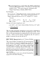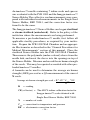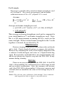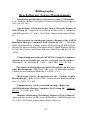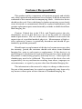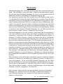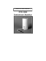
1
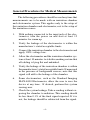
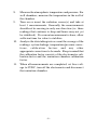
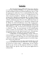
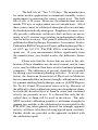
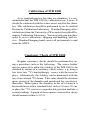
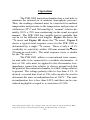
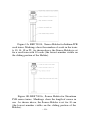
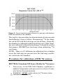
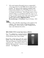
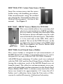
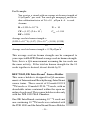
SeeDOS User Manual
IVB 1000
Ionization Chamber
Table of Contents
General Precautions ...................................................... 2
Features and Specifications .......................................... 3
General Procedures for Medical Measurements ........... 4
Overview ...................................................................... 6
Calibration of IVB 1000 ............................................... 8
Constancy Check of IVB 1000 ..................................... 8
Operation ...................................................................... 9
90
Procedures for Calibration of IVB Sr sources .......... 11
192
Procedures for Calibration of IVB Ir sources ......... 13
Procedures for Other Source Holders ......................... 16
Maintenance................................................................ 25
Service ........................................................................ 25
Brachytherapy Parts List ............................................ 26
Bibliography; Brachytherapy Measurements ............. 27
Customer Responsibility ............................................ 28
Warranty ..................................................................... 29
© 2002 Standard Imaging Inc.
7601 Murphy Drive
Distributed
Middleton,
WI 53562
by SeeDOS
Phone:Ltd
(608) 831-0025
Fax:
(608) 831-2202
Please contact [email protected]
General Precautions
Warnings and Cautions alert users to dangerous conditions that can occur if instructions in the manual are not
obeyed. Warnings are conditions that can cause injury to
the operator, while Cautions can cause damage to the equipment.
WARNING: Electrical shock hazard when connected to 300
V bias supply. Do not remove cover.
CAUTION: Proper use of this device depends on careful reading of all instructions and labels.
CAUTION: This device should never be submerged to clean
or scrubbed with an abrasive cleaner.
CAUTION: Do not drop, mishandle, or disassemble unit since
it may result in change of calibration factor. Refer
all servicing to qualified individuals.
CAUTION: Do not sharply bend triax cable. Damage to the
cable may result in high leakage currents.
CAUTION: Insure source freely moves within secured catheter. Proper location of source is necessary to
assure proper calibration.
– 2–
Features and Specifications
Active Volume
475 cm3
ADCL Calibrations
Various single seed, 90Sr/90Y beta
Isotope Source Holders......
Iridium IVB Source Holder, REF 70034
Strontium IVB Source Holder, REF 70036
X-Ray Contamination Test Tool, REF 70042
IVB Single Seed LDR Source Holder, REF 70043
IVB HDR Source Holder, REF 70044
IVB Cesium 5mm Source Holder, REF 70045
IVB Cesium 7mm Source Holder, REF 70046
Mick® Source Holder, REF 70047
Seed Strand Source Holder, REF 70048
IBt InterStrand® Source Holder, REF 70049
Imagyn isosleeve™ Source Holder, REF 70050
Connector
Cable
Bias Voltage Applied
Leakage
Stability
Response
Sensitivity
Aion
Case
Dimensions
Height
Diameter
Insert Diameter
Insert Height
Weight
Two lug triax (standard), TNC, or
Type M
1 meter (3 feet)
±300 volts, typical
Less than 50 fA
0.2% (Reproducibility )
± 0.3% over 100mm at center of
axis, typical
2.4 pA/U typ for 192Ir
38.5 nA/Gy/s typ for 90Sr
1.000
Rugged carrying case
25.9 cm (10.2 in.)
10.2 cm (4.0 in.)
3.5 cm (1.4 in.)
22.4 cm (8.8 in.)
3.6 kg (8.0 lbs)
–3–
General Procedures for Medical Measurements
The following procedures should be used any time that
measurements are to be made with an ionization chamber
and electrometer system. This applies only to the setup of
the ionization chamber and electrometer, not to the setup of
the ionization source.
1.
With nothing connected to the input jack of the electrometer, turn the power on and wait at least 15
minutes for warm up.
2.
Verify the leakage of the electrometer is within the
manufacturer’s stated acceptable limits.
3.
Connect the ionization chamber to the electrometer and
apply 100% voltage bias.
4.
Allow the electrometer and the ionization chamber system at least 10 minutes to stabilize,making certain that
all cabling is lying flat and unkinked.
5.
Verify the leakage of the ionization chamber is within
the manufacturer’s stated acceptable limits. If measured
in the presence of background sources, note that this
signal will add to the leakage of the chamber.
6.
Some electrometers, such as the Standard Imaging
MAX-4000 Electrometer, allow the user to zero the
device at any time. If desired, perform this system
zeroing now.
7.
Check the system leakage. Take a reading without exposing the chamber to radiation. This reading should
be less than 0.1% of the final signal expected. If it is
not, the leakage should be subtracted from the signal.
– 4–
8.
Measure the atmospheric temperature and pressure. For
well chambers, measure the temperature in the well of
the chamber.
9.
Turn on or insert the radiation source(s) and take at
least 3 measurements. Generally the measurements
should not be moving in only one direction (i.e. three
readings that continue to drop and hence may not yet
be stabilized). If a current measurement is done, allow
sufficient time for value to stabilize.
10.
Analyze the data taking into account the average of the
readings, system leakage, temperature/pressure corrections, calibration factors and any other
appropriate corrections to be made. Keep in mind that
the calibration factor consists of the electrometer calibration factor and the ionization chamber calibration
factor.
11.
When all measurements are completed, set bias voltage to 0VDC, turn off the electrometer and disconnect
the ionization chamber.
–5–
Overview
The Standard Imaging IVB 1000 Ionization chamber
is a well-type ionization chamber. It is specifically designed
for measurement of Intravascular brachytherapy sources, with
the appropriate calibration. It is recommended that the chamber be calibrated every two years as is standard practice for
other ionization chambers. Initially, the calibration factor is
given in the calibration report from the Accredited Dosimetry Calibration Laboratory (ADCL). The appendix provided
with the calibration report discusses the calibration factors in
greater detail. Calibration factors should be obtained from
an ADCL for each brachytherapy source that is being measured. The ionization current expected from the IVB 1000 is
approximately 2.4 pA/U for 192Ir brachytherapy sources and
38.6 nA/Gy/s for 90Sr. U is the unit for air kerma strength and
is µGym2h-1. Thus, the measurement of all brachytherapy
sources requires an electrometer with a calibrated scale for
measuring currents in the range from pA to nA. Alternatively,
a calibrated charge scale may be used with timed runs.
Calibration of all brachytherapy sources with ionization chambers is important. When a brachytherapy source
is used, it is imperative that there be an accurate and reliable
calibration of the source strength by means of a suitable chamber, such as the IVB 1000.
Using other inserts, low dose rate brachytherapy seeds
can also be calibrated with the IVB 1000. Use the appropriate insert for a given source. Additionally, do not confuse
details in one section of this manual with those of another.
Some details are specific only for the given application or
radionuclide.
– 6-
The half life of 192Ir is 73.83 days. The manufacturer
for intravascular applications recommends monthly source
replacements to maintain the correct output level. The half
life of 90Sr is 28 years. However, the manufacturer recommends 250 uses or replacement on a six month basis. All of
these sources must be calibrated when placed in use and may
be checked periodically during use. Suppliers of sources usually provide calibration certificates that can have an uncertainty of ±4% or more, necessitating an independent calibration for better accuracy. This point is addressed in the article
published in Brachytherapy Dosimetric Assessment: Source
Calibration,RSNA Categorical Course in Brachytherapy Physics 1997, pp. 143-153. The IVB 1000 is convenient for frequent use. If your measurement differs significantly from
the manufacturer, you should resolve the difference before
use.
Please note that the factors that are used in the calibration of these chambers are the most current, and in some
cases, may be different than those used in treatment planning
computers. This difference, if present, should be accounted
for during your treatment planning activities. To avoid confusion, the American Association of Physicists in Medicine
has recommended that air kerma strength calibrations be used
for gamma emitting brachytherapy sources (AAPM Reports
No. 56, 60, 40 and 32) instead of source activity. Because of
the difficulty of beta calibrations using an extrapolation chamber both the absorbed dose at 2mm in water and contained
activity are presently in use. It is desired that only the absorbed dose at 2mm will be used in the future. The only
NIST traceable calibration quantity is air kerma strength for
gamma rays and this is the calibration factor provided for the
IVB 1000. Any other quantity desired, for example, apparent
activity, will have to be derived using agreed upon constants.
Further details are provided in the appendix included with
the calibration report.
– 7–
Calibration of IVB 1000
As is standard practice for other ion chambers, it is recommended that the IVB 1000 be calibrated every 2 years. It
should be calibrated with the source insert used for the chamber. This calibration should be performed by an Accredited
Dosimetry Calibration Laboratory. Standard Imaging offers
calibrations from the University of Wisconsin Accredited Dosimetry Calibration Laboratory. You need only one purchase
order to cover calibrations, shipping and handling, and service. Standard Imaging hand carries all instruments to and
from the ADCL.
Constancy Check of IVB 1000
Regular constancy checks should be performed by using a procedure such as the following. The source holder
may be removed to allow the stability of the IVB 1000 to be
checked by means of a constancy check source, e.g. using a
low dose rate 137Cs brachytherapy source with the insert in
place. Alternatively, the stability can be monitored with the
use of an external 60Co beam. This value should be obtained
upon receipt of the chamber and monitored for consistency
thereafter. Either place the chamber in the 60Co beam at a
known distance with a standard field, such as 10 cm x 10 cm,
or place the 137Cs source in a reproducible position and take a
current reading. A graph of the response corrected for decay
should remain within +/-0.5%.
– 8–
Operation
The IVB 1000 ionization chamber has a vent hole to
maintain the internal air at ambient atmospheric pressure.
Thus, the readings obtained must be corrected for ambient
temperature and pressure to the temperature and pressure of
calibration (22o C and 760 mm Hg) at “normal” relative humidity (50% ± 25% non-condensing) in the usual accepted
manner. The IVB 1000 has variable inserts available that
can be set for different seed lengths. Figure 1A shows the
192
Ir insert and Figure 1B shows the 90Sr insert. Figure 2
shows a typical axial response curve for the IVB 1000 as
determined by a single 192Ir source. There is only a +0.3%
variability in sensitivity within 100 mm around the center
(50 mm on each side). The axial response curve is similar
for the 90Sr source.
The IVB 1000 utilizes a conventional triax connector and cable to be connected to a suitable electrometer. A
bias of 300 volts must be applied to the electrometer lowimpedance connection relative to chassis ground such that
the guard of the ionization chamber is at this voltage relative
to ground. The voltage polarity effect is less than 0.1%. If
desired, a second bias level of 150 volts can also be used to
determine the ionic recombination loss at 300 V. 1 The ionic
recombination loss is less than 0.05% and thus can be considered negligible or equal to a correction of 1.000.
1 The equation used is A
ion = 4/3 - (Q1/3Q2), where Q1 is the charge or current measured at 300 V
and Q2 is the charge or current measured at 150 V. See Med. Phys. 11: 714 (1984).
–9–
Figure 1A: REF 70034, Source Holder for Iridium IVB
seed trains. Markings show the number of seeds in the train:
6, 10, 14, 18 or 22. As shown above, the Source Holder is set
for a seed train with 10 seeds (the lowest number visible on
the sliding portion of the Holder).
Figure 1B: REF 70036, Source Holder for Strontium
IVB source trains. Markings show the length of source in
cm. As shown above, the Source Holder is set for 30 cm
(the lowest number visible on the sliding portion of the
Holder).
– 10–
Figure 2: Typical axial response shown as a percent with distance
from the bottom of the chamber.
The step by step procedure for measurement of intravascular
brachytherapy sources follows. If measuring 192Ir, the chamber can be left with the lead rings on it at all times. Generally
the chamber is calibrated with the lead rings on it. If the chamber was calibrated without the lead rings, it should be used in
that manner. DO NOT use lead rings when calibrating 90Sr
seed trains.
NOTE: There is a 1% difference in calibration factor whether
or not the lead rings are present since the lead rings contribute scatter into the chamber.
Procedures for calibration of IVB 90Sr sources
REF 70036, Strontium IVB Source Holder for 90Sr sources
1.
If necessary, let the IVB 1000 Chamber equilibrate to
ambient temperature and pressure for at least 30 minutes before the measurement.
90
WARNING: NEVER cut the catheter for Sr source trains
(manufactured by Novoste).
– 11–
2.
Connect the IVB 1000 Chamber to a suitable electrometer, such as the MAX 4000 from Standard Imaging,
and apply 300 V bias voltage. Allow the system to stabilize for at least 10 minutes. Be sure to use the bias
voltage with which the IVB 1000 was calibrated.
3.
Set the Source Holder to the length of source to be measured: 30, 40 or 60mm. This is indicated by the lowest
number visible on the Source Holder. See Figure 1B.
Insert the Source Holder into the IVB 1000.
4.
Carefully slide the Source Catheter into the top opening in the knurled knob on the Source Holder. Insert
the Catheter until it bottoms, about 7.5” deep.
5.
Secure the Source Catheter by tightening the Knurled
Knob until the Catheter no longer moves up and down
easily. Do not tighten too far so the source is unable to
pass completely into the Source Holder, or that the catheter is kinked or damaged.
6.
After performing all manufacture recommended safety
procedures for the IVB seed train, run the seed train to
the bottom of the Calibration Catheter (Verify again
that the setting on the Source Holder matches the
number of seeds in the train). Let the reading stabilize
for a minimum of 20 sec for current measurement or
for a reproducible set time for charge measurement.
7.
Read and record the measured current or charge at five
positions (e.g. rotate the Source Holder in the Well chamber to the compass positions of 0°, 90°, 180°, 270°,
and 360° for succesive measurments). Take the average of the readings.
8.
Use correction factors for temperature/pressure, electrometer correction factor (electrometer must be calibrated) and calibration factor for the IVB 1000 given
– 12–
by the Accredited Dosimetry Calibration Laboratory to calculate the absorbed dose rate at 2mm for the source. The
following equation can be used
Dw = R * F * E * C
where:
Dw = the absorbed dose rate at 2mm depth in water
R = the reading in A (if current scale) or in C/s (if charge
scale measured for a set time in s)
F = the temperature and pressure correction factor
E = the correction factor for the electrometer scale
C = the IVB 1000 calibration factor
Note: “Dw” can be divided by Aion if desired to correct for
recombination effects. Since the IVB 1000 has an Aion of
1.000, this is not necessary.
The value of Dw will give the total absorbed dose rate at 2mm
for the source length measured.
For example, if R = 6.220 n A, F = 1.009, E = 0.999 and C =
42 Gy/s/nA, then
Dw=(6.220nA) * (1.009) * (0.999) * (42Gy/s/nA) = 263Gy/s
Note: A calibration factor is also given for contained activity. The equation above is still used with C being replaced
by the calibration factor for contained activity. The result
obtained is then the “contained activity” instead of Dw.
Procedures for calibration of IVB 192Ir sources
REF 70034, Iridium IVB Source Holder for LDR
seeds
1.
192
Convert a Treatment Catheter to a Calibration
Catheter if required.
192
WARNING: This is only applicable for IVB Ir
sources and only if a Calibration Catheter has not
been provided or fabricated.
– 13–
Ir
Figure 3: Converting a Treatment Catheter to a
Calibration Catheter for 192Ir IVB sources
Using a sharp exact-o knife, cut off the blue tip of a
192
Ir treatment catheter as shown in Figure 3. Retain
this Calibration catheter and use with all future source
calibrations.
192
Warning: This procedure is only for IVB Ir sources.
2.
3.
4.
5.
Place the IVB 1000 Chamber with the lead rings around
it as calibrated. If necessary let the chamber stabilize
for at least 30 minutes before the measurement to allow it to equilibrate to ambient temperature and pressure.
Connect the IVB 1000 Chamber to a suitable electrometer, such as the MAX-4000 from Standard Imaging,
and apply 300 V bias voltage. Allow the system to
stabilize for at least 10 minutes.
Set the Source Holder to the number of seeds to be
measured: 6, 10, 14, 18 or 22. This is indicated by the
lowest number visible on the Source Holder. See Figure 1A. Insert the Source Holder into the IVB 1000.
Carefully slide the blue-tipped end of the Calibration
Catheter into the top opening in the knurled knob on
the Source Holder. Insert the Catheter until it bottoms
within the Source Holder (about 7.5”).
– 14–
6.
7.
Secure the Calibration Catheter by tightening the
Knurled Knob until the Catheter no longer moves up
and down easily. Do not tighten too far so the IVB seed
train is unable to pass completely into the Source Holder.
After performing all manufacturer recommended safety
procedures for the IVB seed train, run the seed train to
the bottom of the Calibration Catheter (Verify again that
the setting on the Source Holder matches the number of
seeds in the train). Let the reading stabilize for a minimum of 20 sec for current measurement or for a reproducible set time for charge measurement.
8.
Read and record the measured current or charge.
9.
Use correction factors for temperature/pressure, electrometer correction factor (electrometer must be calibrated) and calibration factor for the IVB 1000 given
by the Accredited Dosimetry Calibration Laboratory to
calculate the air kerma strength of the source. The following equation can be used
Sk = R * F * E * C
where:
Sk = the air kerma strength of the source
R = the reading in A (if current scale) or in C/s (if charge
scale measured for a set time in s)
F = the temperature and pressure correction factor
E = the correction factor for the electrometer scale
C = the IVB 1000 calibration factor for air kerma strength
Note: “Sk” can be divided by Aion if desired to correct for
recombination effects. Since the IVB 1000 has an Aion of
1.000, this is not necessary.
The value of Sk will give the total air kerma strength for the
number of seeds measured within +0.3%. For example, if R
= 6.220 n A, F = 1.009, E = 0.999 and C = 421 U/nA, then
– 15–
Sk = (6.220nA) * (1.009) * (0.999) * (421U/nA) = 2640 U
If the value of air kerma strength is for a number of seeds
and the individual value of each seed is desired, divide the
value by the number of seeds in the train. The value for
absorbed dose rate at 2mm is determined using AAPM task
group 60 report.
Procedures for Other Source Holders
REF 70042, X-Ray Contamination Test Tool
This tool is designed for use with 90Sr sources only. It consists of a 7mm radius of material that absorbs nearly all of the
beta particles. Thus, it allows only the x-rays created in the
encapsulation of the seeds to be detected.
1.
2.
3.
4.
5.
6.
After the calibration measurement of a 90Sr source
train with the Strontium source holder, REF 70036,
loosen the knurled knob and remove the calibration
catheter and source holder from the IVB 1000.
Place the X-Ray Contamination Test Tool into the
IVB 1000. Slide the catheter into the opening in the
knurled knob on the source holder and insert it until
it bottoms within the source holder.
Secure the catheter by tightening the knurled knob
until the catheter no longer moves up and down
easily. Do not tighten too far so the seed train is
unable to pass completely into the source holder.
Inject the source, following the source manufacturer’s instructions.
Read and record the measured current or charge.
Calculate the ratio of this reading with the calibration reading taken with the Strontium source holder,
REF 70036. A representative value is 2.76 x 10⁻³ +
0.5%.
– 16–
REF 70043, IVB Single Seed Source Holder
1.
2.
Insert an individual seed into the center tube of the
source holder. The source holder will place the seed
at the most active area of the chamber.
Take a measurement. A seed can be removed by
removing the source holder and inverting. The center
tube will allow the seed to easily slide out. ADCL
calibrations are available for LDR iridium, iodine and
palladium seeds. ADCL calibrations are not available
for gold.
REF 70044, IVB HDR Source Holder
1.
2.
3.
4.
5.
6.
Place the IVB 1000 Ionization chamber in the same
room as the HDR unit for at least 30 minutes before
the measurement to allow it to equilibrate to ambient
temperature and pressure.
Connect the IVB 1000 Ionization chamber to a
suitable electrometer, such as the MAX-4000 from
Standard Imaging, and apply 300 V bias voltage.
Allow the system to stabilize for at least 10 min.
Connect a catheter, such as the endobronchial,
French 6 blue catheter to HDR irradiator.
Align the black dot on the well insert with the punch
mark on the body of the chamber.
Insert catheter end to bottom of source holder. The
dead space at the catheter end must be known, so
192
that the center of the Ir source can be positioned at
the most sensitive spot of the chamber. See Figure
2, page 11 for a typical axial response curve for the
IVB. Use the point determined during calibration as
the sensitive spot for the IVB 1000.
Secure the catheter by tightening the knurled knob,
until the catheter no longer moves up and down
easily. Do not tighten too far so the HDR source is
unable to pass completely into the Source Holder.
– 17–
7.
After performing all manufacturer recommended
safety procedures for the HDR after-loading device,
192
run the Ir source to the radiation sensitive axial
point of the chamber for a minimum of 20 sec for
current measurement or for a reproducible set time
for charge measurement. If the charge mode is used
and the charge is accumulated while the source is in
transit, account for the transit time error of the source
by making the standard timer end effect measurements as described in High Dose Rate
Brachytherapy: A Textbook, Nag, ed. Futura, 1994.
Note:
This value will differ depending on the length of the
catheter. The timer feature of Standard Imaging
electrometers can be used to collect charge for set
times and eliminate this effect.
REF 70045, IVB Cesium 5mm Source Holder
137
For Cs calibrations, verify the plastic
spacer inside the source holder insert is
at the bottom of the source holder.
Insert the cesium source into the source
holder using safe handling procedures.
Take measurements using the method described in the “General Procedures for
Medical Measurements” Section of this
manual. See Figure 4.
– 18–
REF 70046, IVB Cesium 7mm Source Holder
Insert the cesium source into the source
holder using safe handling procedures.
Take measurements using the method
described in the “General Procedures for
Medical Measurements” Section of this
manual. See Figure 5.
Figure 5: REF 70046
REF 70047, MICK® Source Holder for IVB 1000
This source holder allows for a constancy QA
check of seeds loaded into a MICK cartridge.
Screw a loaded cartridge into the holder from
the bottom as shown and make sure the seeds
are not blocked by the metal posts. This holder
is to be used only in the IVB 1000, and is
marked “For use in the IVB1000 only” on the
top label. For measurement in the HDR 1000
Plus Well chamber, use Source Holder REF
Figure 6:
REF 70047 70023. See Figure 6.
REF 70048, Seed Strand Source Holder
This source holder is designed for QA measurements of
RAPID Strand 6711 Iodine seed strands prior to use, and is
designed for use only with the IVB 1000 Well Chamber.
A RAPID Strand containing 10 iodine seeds was evaluated
with the IVB 1000 and the Seed Strand Source Holder. Following the evaluation, seeds of the RAPID Strand were cut
from the strand. The collective seed measurements were compared with individual seed measurements in the Single Seed
Source Holder, REF 70043, to obtain a correction factor. This
factor was found to be approximately 1.07 times the 6711
Iodine seed calibration factor from the University of Wisconsin Accredited Dosimetry Calibration Laboratory.
– 19–
The results of the above testing apply specifically to the submitted strand type and well chamber. Application of these
results to any well chamber and its associated holder may
result in errors due to differences in manufacturing processes,
component composition, and the effects of different stranded
seed trains to those variations. It is recommended that this
investigation be repeated by users upon initial receipt of this
holder to verify this number.
The Seed Strand Source Holder, REF 70048, can be gas
sterilized or steam sterilized (autoclaved).
To measure a RAPID Strand source, raise the lift knob on
the top of the source holder as far as possible, and insert the
strand in its amber-colored spacing jig. There is a plastic
key on the bottom of the housing to guide the spacing jig so
the seeds are in the center of the well chamber. Lower the
lift knob, and measured activity of all ten seeds in the strand.
Inverting the RAPID Strand is not necessary. To measure
more Rapid Strand sources, simply raise the lift knob, and
remove the measured RAPID Strand from the holder.
A formula can be used to determine the average seed air kerma
strength (AKS) as a QA measurement of the sum of 10 seeds.
Average seed air kerma strength= R * CF * CT/P * EF
N
R = reading
CF(correction factor) = ~ 1.07 times the ADCL
iodine calibration factor for
Amersham 6711 seeds,
obtained with Single Seed
Source Holder, REF 70043
N
= number of seeds
CT/P = correction for temperature and pressure
EF = electrometer correction factor
– 20–
For Example:
You receive a strand with an average air kerma strength of
2 -1
0.3µGym h per seed. Ten seeds are measured, and an io11
2 -1 -1
dine calibration factor of 2.6 x 10 µGym h A is used.
Assume:
-11
R = 0.9914 x 10 A
N = 10
11
CF = (1.07) (2.6 x 10 )
C
= 1.014
T/P
EF = 0.998
Average seed air kerma strength =
-11
11
(0.9914 x 10 A) (1.07) (2.6 x 10 ) (1.014) (0.998)
10
2 -1
Average seed air kerma strength = 0.28 µGym h
This average seed air kerma strength can be compared to
your expected RAPID Strand average seed air kerma strength.
Note, this is a QA measurement assuming the ten seeds are
the same activity. If the total air kerma strength for the 10
seeds together is desired, do not divide by N.
®
REF 70049, IBt InterStrand Source Holder
This source holder is designed for QA measurements of International Brachytherapy InterStrand
source trains. These consist of 10 model 1031L
103
Pd seeds or 10 model 1251L 125I seeds, with an
absorbable suture contained within the open annulus of each seed. This source holder works only
with the IVB 1000 Well Chamber.
125
One IBt InterStrand containing 10 I seeds and
103
one containing 10 Pd seeds was evaluated with
the IVB 1000 and the InterStrand Source Holder.
– 21–
Following measurement, individual seeds of the InterStrand
were removed from the suture material. The collective seed
measurements were compared with individual seed measurements in the Single Seed Source Holder, REF 70043, to obtain a correction factor. This factor was found to be approxi125
mately 0.97 times the model 1251L I seed calibration factor from the University of Wisconsin ADCL and 0.92 times
103
the model 1031L Pd seed calibration factor.
The IBt InterStrand Source Holder, REF 70049, can be gas
sterilized or steam sterilized (autoclaved). Refer to the
policy of the institution performing the measurements.
To measure an InterStrand source train , prepare the IVB 1000
Well Chamber and an appropriate Electrometer as described
in the “General Procedures for Medical Measurements” section of this manual. Following sterility and radiation safety
procedures, remove the cover from the InterStrand Stainless
Steel Shielding Container. Invert the Source Holder, and
thread the exposed portion of the Container into the Source
Holder. Return the Source Holder to the upright position.
This should cause the InterStrand to slide out of the container
directly into the Source Holder, which should be visually
verified. Insert the Source Holder into the IVB Well Chamber and measure and record the air kerma strength of the seed
train. To remove the train, simply reverse the above steps.
This may be repeated as needed with other InterStrand sources.
A formula can be used to determine the average air kerma
strength (AKS) per seed as a QA measurement of the sum of
N seeds.
Average air kerma strength per seed = R * CT/P * EF * CF
N
R
= reading
N = number of seeds
CT/P = correction for temperature and pressure
EF = electrometer correction factor
– 22–
CF(correction factor) = 0.97 times
the ADCL calibration
125
factor for IBt model 1251L I seeds or 0.92 times the
103
model 1031L Pd seed cal factor, obtained with
Single Seed Source Holder, REF 70043
For Example:
125
You receive an I InterStrand with a stated air kerma strength
2 -1
per seed of 0.3 µGym h . Ten seeds are measured, and an
11
2 -1 -1
iodine calibration factor of 2.6 x 10 µGym h A is used.
Assume:
-11
R = 1.0971 x 10 A
EF = 0.998
N = 10
CT/P = 1.014
11
CF = (0.97) (2.6 x 10 )
Average air kerma strength per seed
-11
11
= [(1.0971 x 10 A)(1.014)(0.998)(.97)(2.6 x 10 )]/10
2 -1
= 0.28 µGym h
This average air kerma strength per seed can be compared to
your stated InterStrand air kerma strength per seed. Note
this is a QA measurement assuming the ten seeds are the same
activity. If the total air kerma strength for the 10 seeds together is desired, do not divide by N.
REF 70050, Imagyn isosleeve™ Source Holder
This source holder is designed for QA measurements
of the isosleeve™ prostate brachytherapy needle delivery system from Imagyn Medical Technologies.
Each isosleeve™ needle is provided sterilized and
custom-loaded according to the treatment plan. The
polyimide sleeve within the isosleeve™ needle contains the seeds and spacers and may be removed from
the needle hub so that the seeds can be assayed in the
source holder.
This source holder works only with the Standard Imaging IVB 1000 Well Chamber.
– 23–
An isosleeve™ needle containing 7 iodine seeds and spacers
was evaluated with the IVB 1000 and the Imagyn isosleeve™
Source Holder. The collective seed measurements were compared with individual seed measurements in the Single Seed
Source Holder, REF 70043, and the correction factor was
found to be the same.
The Imagyn isosleeve™ Source Holder can be gas sterilized
or steam sterilized (autoclaved). Refer to the policy of the
institution where the measurements are being performed.
To measure a pre-loaded isosleeve™ needle, first follow all
applicable sterility procedures, as required by your institution. Prepare the IVB 1000 Well Chamber and an appropriate Electrometer as described in the “General Procedures for
Medical Measurements” section of this manual. Place the
sterilized Source Holder into the IVB 1000 Well Chamber.
Then remove the polyimide (amber-colored) sleeve from the
needle hub, and insert the sleeve into the opening on top of
the Source Holder. Measure and record the air kerma strength
of the seeds. This may be repeated as needed with other preloaded isosleeve™ needles.
A formula can be used to determine the average air kerma
strength (AKS) per seed as a QA measurement of the sum of
N seeds.
Average air kerma strength per seed = R * CF * CT/P * EF
N
R
= reading
CF(cal factor) = The ADCL iodine calibration factor for
Imagyn isostar™ seeds obtained with
Single Seed Source Holder, REF 70043
N
= number of seeds
CT/P = correction for temperature and pressure
EF = electrometer correction factor
– 24 –
For Example:
You receive a needle with a stated air kerma strength per seed
2 -1
of 0.3µGym h . Five seeds are measured, and an iodine
11
2 -1 -1
calibration factor of 2.6 x 10 µGym h A is used.
Assume:
-11
R = 0.5321 x 10 A
C = 1.014
N = 5
CF = 2.6 x 10
EF = 0.998
11
T/P
Average air kerma strength per seed
-11
11
= [(0.5321 x 10 A)(2.6 x 10 ) (1.014) (0.998)]/5
2 -1
= 0.28 µGym h
This average air kerma strength per seed can be compared to
your stated isosleeve™ air kerma strength per seed. Note,
this is a QA measurement assuming the five seeds are the
same strength. If the total air kerma strength for the 5 seeds
together is desired, do not divide by N.
Maintenance
Exterior cleaning of the device can be done with a soft brush
and a cloth. Gently brush all surfaces to remove dirt and dust.
Remove any remaining dirt with a cloth slightly dampened with
a solution of mild detergent and water or a liquid disinfecting
agent. Be especially careful that this is an external cleaning only
and do not permit any liquid to seep into the IVB 1000 in any
manner during cleaning.
Service
There are no serviceable parts on the IVB 1000. If the IVB
1000 is disassembled, the calibration factor will become invalid
and necessitate recalibration. Also, the warranty will become
void if the IVB 1000 is disassembled. If the triax connector and
external cable are modified, the value of the leakage may be affected.
Notice: We welcome your evaluation of this manual. Your comments
and suggestions help us improve our publications.
–25–
Brachytherapy Measurement System
Parts and Accessories List
REF
80289
70034
70036
70042
70043
70044
70045
70046
70047
70048
70049
70050
Description
Instruction Manual
Iridium IVB Source Holder for LDR 192Ir
Strontium IVB Source Holder for 90Sr
X-Ray Contamination Test Tool
IVB Single Seed Source Holder
IVB HDR Source Holder
IVB Cesium 5mm Source Holder
IVB Cesium 7mm Source Holder
Mick® Source Holder
Seed Strand Source Holder
IBt InterStrand® Source Holder
Imagyn isosleeve™ Source Holder
70125
One Inch thick lead rings to surround IVB 1000 (set of six)
80010
ADCL Calibration for High Dose Rate 192Ir
80020
ADCL Calibration for Cesium
80025-A ADCL Calibration for low dose rate 192Ir, Alpha-Omega Services
80025-B ADCL Calibration 192Ir, Best
80035
ADCL Calibration for Palladium
80036
ADCL Calibration 90Sr, Novoste Medical
80040-A ADCL Calibration for Iodine, Amersham 6702
80040-B ADCL Calibration for Iodine, Amersham 6711
80040-C ADCL Calibration for Iodine, Mentor IoGold
80040-D ADCL Calibration for Iodine, Best Industries
80040-E ADCL Calibration for Iodine, Bebig/Uromed
80040-F ADCL Calibration for Iodine, Mills, Biopharmaceuticals
80040-G ADCL Calibration for Iodine, Syncor
80040-H ADCL Calibration for Iodine, Imagyn
80040-I ADCL Calibration for Iodine, Implant Sciences
80040-J ADCL Calibration for Iodine, International Brachytherapy
80040-K ADCL Calibration for Iodine, Source Tech
80040-L ADCL Calibration for Iodine, DRAXIMAGE, Inc.
Other Calibrations available
Optional Equipment
90015
MAX-4000 Electrometer
– 26–
Bibliography;
Brachytherapy Source Measurements
“Brachytherapy Dosimetric Assessment: Source Calibration,”
L. A. DeWerd, RSNA Categorical Course in Brachytherapy Physics
1997, pp.143-153.
“Specification of Brachytherapy Source Strength, Report of
Task Group 32,” American Association of Physicists in Medicine,
AAPM Report No. 21, (1987). New York: American Institute of Physics.
“Intravascular brachytherapy physics: Report of the AAPM
Radiation Therapy Committee Task Group No. 60,” — Ravinder
Nath, Howard Amols, Charles Coffey, Dennis Duggan, Shirish Jani,
Zuofeng Li, Michael Schell, Christopher Soares, James Whiting, Patricia
E. Cole, Ian Crocker, and Robert Schwartz; Med. Phys. 26 pp.119-152,
(1999).
“Clinical implementation of AAPM Task Group 32 recommendations on brachytherapy source strength specifications,”
Williamson, J.F. and Nath, R., (1991). Med. Phys. 18: 439-448.
The American Brachytherapy Society Perspective on Intravascular Brachytherapy, Subir Nag, MD et al (15 additional authors),
Cardiovascular Radiation Medicine 1:1(1999): 8-19.
“Radiation Safety Requirements for Cardiovascular
Brachytherapy,” Billy G. Bass, PhD, Cardiovascular Radiation Medicine 1:3 (1999): 297-306.
“Comprehensive QA for radiation oncology: Report of
AAPM Radiation Therapy Committee Task Group 40,” Medical
Physics. 21(4):581-618, 1994.
“Remote Afterloading Technology, Report of Task Group 41”
American Association of Physicists in Medicine, AAPM Report No.
41, (1993). New York: American Institute of Physics.
– 27–
Customer Responsibility
This product and its components will perform properly and reliably
only when operated and maintained in accordance with the instructions
contained in this manual and accompanying labels. A defective device
should not be used. Parts which may be broken or missing or are clearly
worn, distorted or contaminated should be replaced immediately with
genuine replacement parts manufactured by or made available from Standard Imaging Inc.
Caution: Federal law in the U.S.A. and Canada restricts the sale,
distribution, or use of this device to, by, or on the order of a licensed
medical practitioner. The use of this device should be restricted to the
supervision of a qualified medical physicist. Measurement of high activity radioactive sources is potentially hazardous and should be performed by qualified personnel.
Should repair or replacement of this device become necessary after
the warranty period, the customer should seek advice from Standard
Imaging Inc. prior to such repair or replacement. If this device is in
need of repair, it should not be used until all repairs have been made and
the product is functioning properly and ready for use. After repair, the
chamber may need to be calibrated. The owner of this device has sole
responsibility for any malfunction resulting from abuse, improper use
or maintenance, or repair by anyone other than Standard Imaging Inc.
The information in this manual is subject to change without notice.
No part of this manual may be copied or reproduced in any form or by
any means without prior written consent of Standard Imaging Inc.
– 28–
Warranty
Standard Imaging, Inc. sells this product under the warranty herein set
forth. The warranty is extended only to the buyer purchasing the product directly from Standard Imaging, Inc. or as a new product from an
authorized dealer or distributor of Standard Imaging, Inc.
For a period of twenty-four (24) months for well chambers and twelve
(12) months for all other Standard Imaging, Inc. products from the date
of original delivery to the purchaser or a distributor, this product is warranted against functional defects in materials and workmanship, provided it is properly operated under conditions of normal use, and that
repairs and replacements are made in accordance herewith. The foregoing warranty shall not apply if the product has been dissembled, altered
or repaired other than by Standard Imaging, Inc. or if the product has
been subject to abuse, misuse, negligence or accident.
Standard Imaging’s sole and exclusive obligation and the purchaser’s
sole and exclusive remedy under the above warranties are limited to
repairing or replacing free of charge, at Standard Imaging’s option, a
product: (1) which contains a defect covered by the above warranties;
(2) which are reported to Standard Imaging, Inc. not later than seven (7)
days after the expiration date of the 12 or 24 month warranty period; (3)
which are returned to Standard Imaging promptly after discovery of the
defect; and (4) which are found to be defective upon Standard Imaging’s
examination. Transportation charges are the buyer’s responsibility. This
warranty extends to every part of the product except fuses, batteries, or
glass breakage. Standard Imaging, Inc. shall not be otherwise liable for
any damages, including but not limited to, incidental damages, consequential damages, or special damages. Repaired or replaced products
are warranted for the balance of the original warranty period, or at least
90 days.
This warranty is in lieu of all other warranties, express or implied, whether
statutory or otherwise, including any implied warranty of fitness for a
particular purpose. In no event shall Standard Imaging, Inc. be liable
for any incidental or consequential damages resulting from the use, misuse or abuse of the product or caused by any defect, failure or malfunction of the product, whether a claim of such damages is based upon the
warranty, contract, negligence, or otherwise.
This warranty represents the current standard warranty of Standard
Imaging, Inc. Please refer to the labeling or instruction manual of
your Standard Imaging, Inc. product for any warranty conditions
unique to the product.
Doc. No. 80289-09, 03/04/02, 29 pgs
Distributed by SeeDOS Ltd