1
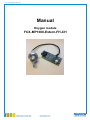
103-12-306-006-EH-0315.pdf Manual Oxygen module FCX-MP1000-Extern-FH-CH 103-12-306-006-EH-0315.pdf The items mentioned in this manual are trademarks and might be used for identification purpose. Output protocol Issue 1.1 Month / Year February 2015 Valid for Software version All rights reserved This document may be used by the receiver for its designated purposes. It mustn’t be copied or translated in any way without special consent in advance. Technical amendments reserved. Copyright: Pewatron AG PEWATRON AG Thurgauerstrasse 66 8052 Zurich Switzerland Tel: +41 (0)44- 877 35 00 Fax: +41 (0)44-877 35 25 [email protected] www.pewatron.com Idt.-Nr. Issue Release 1.1 2.2015 1 103-12-306-006-EH-0315.pdf 1 List of Contents Page 1. List of Contents ............................................................................................................................................................................... 2 2. Customer Service........................................................................................................................................................................... 3 3. Security Information 4. Measuring Principle...................................................................................................................................................................... 5 5. Operation Start ................................................................................................................................................................................ 6 5.1 Mechanical Installation ............................................................................................................................................................. 6 5.2 Pneumatic Connections............................................................................................................................................................. 6 5.3 Electrical Connections ............................................................................................................................................................... 7 5.3.1 Supply ..................................................................................................................................................................................................... 7 5.3.2 Analog Output .................................................................................................................................................................................. 7 6. Environment Conditions ........................................................................................................................................................... 8 7. Warm Up Time ................................................................................................................................................................................ 8 8. Gas Flow .............................................................................................................................................................................................. 8 9. Calibration …....................................................................................................................................................................................... 9 9.1 Calibration Adjustment............................................................................................................................................................... 9 9.2 Calibration Span and Zero...................................................................................................................................................... 9 10 Important Advice .........................................................................................................................................................................10 10.1 Restrictions ......................................................................................................................................................................................10 11. Specifications .................................................................................................................................................................................11 ................................................................................................................................................................... 4 2 103-12-306-006-EH-0315.pdf 2 Customer Service We at PEWATRON AG would like to offer the best possible customer service. Should you have any questions, problems or comments regarding your FCX-MP1000-Extern-FH-CH, we would appreciate if you get in touch with us. We recommend that all services, including repairs of the device, will only be taken care of by either our customer service or by specially trained staff. You can reach us the following address: Headquarter: PEWATRON AG Thurgauerstrasse 66 8052 Zurich Switzerland Tel +41 (0)44-877 35 00 Fax +41 (0)44-877 35 25 E-Mail: [email protected] Internet: www.pewatron.com Before returning anything, please ask for an RMA-No. Tel +41 (0)44 877 35 15 Please send return goods to our Logistic Center: PEWATRON AG Logistic Center Hardhofstrasse 31 8424 Embrach/ZH Switzerland 3 103-12-306-006-EH-0315.pdf 3 Security Information Safety hazards that can endanger humans or do damage to the devices are specially mentioned in the user manual. Before installing the device you should read the instructions carefully. Please take note of all paragraphs that point out possible hazards. Warnings and instructions are expressed as followed: ! Means that ignoring this instruction can endanger humans Warning Means that this instruction has to be followed in order to prevent damage to the device Attention 4 103-12-306-006-EH-0315.pdf 4 Measuring Principle The sensor module is a complete solution for measuring oxygen within the range of 0...1000 ppmO2. The sensor and the electronics are connected via board. The sensor is encapsulated in a pressure tight flow housing. The electronics amplify the sensor signal and transform it into a linear current output signal 4…20mA (according to IEC 60381) In the picture below the schematics of zirconia sensing elements are shown. Zirconium oxide, heated to about 450 °C, is penetrable for oxygen ions. A voltage applied to the sensor therefore pumps the oxygen out of the inner chamber. At a constant gas pressure, the quantity of oxygen pumped out is equal to the quantity of oxygen molecules diffusing in through the capillary, and within a certain range it is independent of the voltage applied between the electrodes. The measurement current it proportional to the quantity of oxygen molecules pumped away. The relationship between the oxygen partial pressure and sensor current is governed by the formula IL = ([A]/1000) x [O2ppm], where IL A pO2 = sensor current = sensor output current in 1000ppm O2 (µA) = oxygen concentration (vol ppmO2) The sensor module performs four tasks: - Regulation of the heating power of the sensor Amplification of the microampere signal from the sensor Linearization of the relation between oxygen partial pressure and sensor current Conversion of the amplified signal into a standardised current output signal The sensor and module are calibrated to one another at the factory. The heating voltage must be custom-adjusted for each sensor to bring the temperature to exactly 450 °C. The sensor is not directly replaceable, and cannot be used with other modules. 5 103-12-306-006-EH-0315.pdf 5. Operation Start 5.1 Mechanical Installation The dimensions of the board are 75 x 40 mm. On every corner are mounting holes with a diameter of 3,5 mm. The board holds highly sensitive switches. While installing make sure that no components get damaged mechanically Attention 5.2 Pneumatical Connections The flow housing has two pressure ports with 6 mm diameter. The flow direction is from the top part (with the bulb-form appearance) to the bottom part where the sensor connecting wires comes out. Do never use silicone tubes. Attention 6 103-12-306-006-EH-0315.pdf 5.3 Electrical Connections 5.3.1 Supply The module gets supplied with 7...28VDC through the clamps 1 (+) and 2 (-), approx. 200mA (24VDC). 5.3.2 Analog Output For the output signal the clamps 3 (+) and 4 (-) can be used. 7 103-12-306-006-EH-0315.pdf 6 Environment Condition Also see item 11 in our specifications, especially for the temperature and humidity range (noncondensing). Not to be operated outdoors. Protect the module against humidity The sensor is best operated in oxygen concentrations below 1000 ppmO2, but can see short periods of atmospheric oxygen (20.9 vol%O2). Continuous exposure (> 2 min) of the sensor with oxygen concentrations above 1 vol%O2 slows the sensor response and limits the lifetime of the sensor. The temperature of the sensor is 450°C. Be aware of possible dangers while handling sensitive gas mixtures. ! Potentially explosive Atmosphere The device mustn’t be opened in a potentially explosive atmosphere. Warning 7 Warm Up Time The modules need a warm up time of approx. 3 minutes 8 Gas Flow The following points should be noted: - The flow should not be less than 0.1 l/min and no greater than 1.0 l/min; ideally, it should be 0.5 l/min. We recommend placing an appropriate filter upstream of the module, since contaminants brought in by the flow can significantly shorten the service life of the sensor. Avoid condensation (H2O) in the sensor housing. 8 103-12-306-006-EH-0315.pdf 9 Calibration All necessary adjustments and calibrations are being done at the production site. The output signal is to be read as followed: pO2 (ppm) = 1000 (ppm) (lout [mA] – 4 [mA]) / 16 [mA] means: pO2: oxygen partial pressure in ppm of the total pressure lout: output current in mA 9.1 Calibration Adjustments and Periodical Check-ups It is recommended to check the device periodically by running it under regular lab conditions and flush the sensor with pure nitrogen (6N) to check the zero-point. After flushing the sensor for 1 minute the output current should be 4.005 +/-0.005 mA. 9.2 Adjustment Span and Zero The modules are calibrated and each module is supplied with a calibration sheet. The result of the measuring at an environmental temperature of 25°C and in pure nitrogen should be 0+/-50 ppm. Should there be higher differences as expected try following procedure. 1 Attach the module to the supply 2 Expose the sensor with a gas with known concentration and in the range 1000+/-10 ppm. 3 After 10min. adjust the output signal using the span potentiometer. In a clean environment the amplifier should have an output signal of 20,00 mA (0,05 mA). 4 Flow pure N2 (6N). 5 After approx. ca. 10min. adjust the output signal to 4,050 mA 0,05 mA using the zero potentiometer. This completes the calibration. 9 103-12-306-006-EH-0315.pdf 10 Important Advice 10.1 Restrictions 1 Don’t separate the sensor from the circuit board. 2 Don’t change the length of the lead wires. 3 Do not continuously operate the sensor in a high oxygen concentration (> 0.1 % O2) If the sensor is exposed to such high oxygen concentration, limited output over 20mA will be observed. Should this happen, please turn off the power source. 4 Please use regulated DC power source with current capacity over 1 ampere/pc. If current capacity is not sufficient, the sensor module will not operate correctly. 5 This sensor module was adjusted for O2-N2 system, so abnormal output maybe observed if there are other gases present. 6 Don’t use in a gas that contains the halogen atoms (F, Cl, Br) such as the flon gas. The sensor will be damaged by decomposition of the flon gas. 7 SOx, NOx und H2S will damage the performance of the sensor. Therefore, please do not use sensor module in the atmosphere that contains these gases. 10 103-12-306-006-EH-0315.pdf 11 Specifications Measurement Ranges : 0...1000 ppmO2 Supply : 24 VDC nominally (7...28 VDC) Current supply : typ. 200 mA (24 VDC). Turn off peak approx. 0,7 A Power Consumption :2W Output : 4...20 mA, linear Accuracy : ±50 ppmO2 Repeatability : ±5% Reading Temperature Influence : measuring faults in % pO2 pO2% x (Te°C – 25°C) / 500 Te = environmental temperature of the sensors Response Time : < 8 sec. T90 Gas Temperature : -10...+50 °C Environmental temperature : -20...+70 °C Humidity : 85% RH non-condensing Dimensions Weight LxWxH : 75 x 40 mm : 100 g 11 We are here for you. Addresses and Contacts Sales Switzerland & Liechtenstein Sales International Key Accounts Matthias Rüegg Ruhbergstrasse 32 CH-9230 Flawil Peter Felder Thurgauerstrasse 66 CH-8052 Zürich Phone+ 41 44 877 35 18 Mobile+ 41 76 491 66 66 Fax + 41 44 877 35 19 Phone+ 41 44 877 35 05 Mobile+ 41 79 406 49 83 Fax + 41 44 877 35 25 [email protected] [email protected] Sales Austria Sales Germany Postcode 10000 –59999 Postcode 80000 –99999 Postcode 60000 – 79999 Kurt Stritzelberger Neumarkter Str. 86a D-81673 Munich Dieter Hirthe Auf der Entenweide 4 69502 Hemsbach Kurt Stritzelberger Neumarkter Str. 86a D-81673 Munich Phone+ 49 89 260 38 47 Mobile+ 49 171 803 41 35 Fax + 49 89 43 10 91 91 Tel. + 49 6201 508 9250 Mobil + 49 1637 627 430 Fax + 49 6201 508 9751 Phone+ 49 89 260 38 47 Mobile+ 49 17 18 03 41 35 Fax + 49 89 43 10 91 91 [email protected] [email protected] [email protected] Sales Other Countries / Product Management Sensors Power Supplies E-Components Physical Sensors Data Acquisition DC-DC Converters Switching Power Supplies DC-AC Inverters Current Sensors Man Machine Interface Measurement Probes Sebastiano Leggio Phone+ 41 44 877 35 06 [email protected] Sebastiano Leggio Phone+ 41 44 877 35 06 [email protected] Thomas Clausen Phone+ 41 44 877 35 13 [email protected] PEWATRON AG Thurgauerstrasse 66 CH-8052 Zurich Phone+ 41 44 877 35 00 Fax + 41 44 877 35 25 www.pewatron.com [email protected] Geometrical Sensors Eric Letsch Phone+ 41 44 877 35 14 [email protected] Supporting your great ideas www.pewatron.com